Table of Contents
Advertisement
Quick Links
Advertisement
Table of Contents

Related Manuals for Saci AHM3-SMTP


Summary of Contents for Saci AHM3-SMTP
- Page 1 AHM3-SMTP AHM3RC-SMTP Multifunction Power Meter User Manual VER:V18A...
-
Page 2: Table Of Contents
TABLE OF CONTENTS 1 SAFETY PRECAUTIONS ..............3 2 DESCRIPTION ..................3 ....................3 ENERAL ..................... 3 ODULE ..................4 EASUREMENT ..................... 6 NERGY ....................8 ARMONIC ..................9 OWER UALITY ....................11 EMAND ....................12 (DM1) ..............15 EMORY ODULE (DM2,DM3,DM4)... -
Page 3: Safety Precautions
1 Safety Precautions The manufacturer shall not be held responsible for failure to comply with the instructions in this manual. The equipment must be installed and serviced only by qualified personnel. Never work alone. Prior to any work on or in the equipment,isolate the voltage inputs and auxiliary power supplies,short the secondary of all CT, but never short the secondary of PT. -
Page 4: Measurement
c) Up to four modules can be installed onto meter. Total width of all modules is 4; d) Modules of same type of different types can be installed onto meter in compliance with the requirements of a) ,b)and c). E.g. 1 Four DM2;... - Page 5 The following list shows variables which can be measured by AHM3 including relative variables calculated from basic electrical parameters. Measurement variable Instant Demand unit √ √ √ V1/V2/V3 [V,kV] √ √ √ V12/V23/V31 [V,kV] √ √ √ √ I1/I2/I3 [A,kA] √...
-
Page 6: Energy
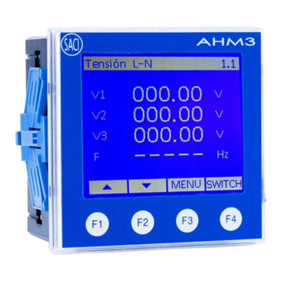
L-N Voltage 1. 1 Left picture shows instantaneous three-phase voltage and frequency. Press 220.55 ▲ ▼ 220.55 button to change to MENU 220.55 other interfaces. Press button return main interface. Press 50.000 SWITCH button to check corresponding ▲ ▼ bar graph interface. MENU SWITCH Left picture shows bar graph of... - Page 7 display the additional 6 Energies and 2 hour meters. Tariff Energy Meter supports tariff energy metering of sixteen time zones at most. The starting of a time zone is judged by meter according digital input status. Bi-direction energy Total Import/Expo rt 2. 1 EP+= 7521.369kWh 07521.369 EP- = 0kWh...
-
Page 8: Harmonic
Hour Counters 2 .13 Hour Counters EP+: Energy Import (EP+): 27h16m 000027 Energy Export (EP-) : 10m h 16 min EP-: 000000 h 10 min ▼ ▲ MENU Harmonic Meter supports harmonic content of grid. Detailed functions are as follows: ·... -
Page 9: Power Quality
Fundamental 105.5 100.7 Left picture shows current fundamental。 110.7 ▲ ▼ MENU H a r m o n i c R a t i o 3. 4 V1 03.9 05.5 01.5 07.5 00.0 06.0 00.0 00.0 Left picture shows harmonic distortion V3 00.0 00.0 00.0 03.0 I1 06.7 03.5 00.0 03.5 rate of three-phase voltage and current. - Page 10 Left picture shows real-time waveform of Waveforms(U) three-phase voltage. "1,2,3" correspond to "V1,V2,V3". ▲ ▼ MENU Left picture shows real-time waveform of 4. 2 Waveforms(I ) three-phase current. "1,2,3" correspond to "I1,I2,I3". ▲ ▼ MENU 2)Phase angle of voltage and current Phase angle of voltage and current of each phase is displayed directly.
-
Page 11: Demand
Electrical parameters of three-phase system are divided into three symmetrical components which positive-sequence component, negative-sequence component and zero-sequence component according to symmetrical component method. ratio values negative-sequence component and positive-sequence component is defined as three-phase unbalance in the condition that power system is in normal operation mode. -
Page 12: Max/Min
Left picture shows maximum demand M a x D e m a n d 5 . 2 value of three phase total active, reactive 3.650 and apparent power. 3.960 kvar 5.385 ▲ ▼ MENU Left picture shows present demand value C u r r e n t P e r i o d 5 . - Page 13 Left picture shows maximum value of M a x V a l u e three-phase voltage and frequency 461.4 639.2 457.7 1.000 ▲ ▼ MENU Left picture shows minimum value of Min Value 6.10 three-phase and total active power 00.00 00.00 00.00 00.00...
- Page 14 Left picture shows “Power off record” Power Off Record including 32 times of power off Num: 0032 latest power off time. Last Time: 14-09-20 09:50:33 ▲ ▼ MENU Left picture shows “Program record” Program Record including 12 times of programming and Num: 0012 latest programming time.
-
Page 15: Memory Module(Dm1
Left picture shows software version of Version CPU: AHM3.1003 meter and module. None indicates that X1: DM6.147A there connection wrong X2: None connection to the interface. X3: None X4: None MENU Modules Meter supports four interfaces for connecting extension modules. Memory Module(DM1)... -
Page 16: Analogue Output Module(Dm5
Left picture show measured value of Module X4 7. 5 PT100 DM3 PT100 thermal resistor. Value 075.5 ℃ First temperature is 75.5℃; 027.6 ℃ Second temperature is 27.6℃. ▲ MENU ▼ Left picture shows measured value of Module X1 7. 2 Thermocoup le-J DM4 thermal couple with graduation number J. - Page 17 Digital Input Digital input adopts dry contact mode. There is internal power supply for digital input so that there is no need for external power supply. There are four working modes for digital input as follows: 1)State monitoring mode:It is used to monitor the state of breaker, the position of handcart, etc.
- Page 18 alarm mode. Parameters like working mode, alarm item, limit value,time delay and hysteresis should be set. The data format of limit value is the secondary integer data. 1) Energy pulse output mode Meter supports bi-directional active and reactive energy pulse output function through relay output.
-
Page 19: Communication
Communication This series power meter provides an RS-485 slave port and adopts Modbus-RTU protocol. All devices are connected in a bus line by twisted-conductor and shielded cable. Up to 32 stations can be connected together in a segment.The cable at the start and end of a segment is terminated with resistors. -
Page 20: Installation
3 Installation Dimensions 50.5 86.5 Mounting 1) Cut a hole in the panel measuring 91×91 mm 2) Take out the power meter and loosen the clips. 3) Insert the meter into the cutout from outside. Wiring 4) Insert the clips and fix the meter. - Page 21 Typical Wiring Diagrams S1 S2 S1 S2 S1 S2 3xFUS. RS485 Rogowski coil Wiring Diagrams (AHM3RC-SMTP) 40 39 3xFUS. RS485 Note: 1. Auxiliary power supply: AC/DC (80~270)V 2. Rated current of fuse: 0.5A...
- Page 22 Signal Wiring Diagrams Note: (a) External wiring mode should be the same as internal wiring mode of meter. Otherwise, measured information of meter will be not correct (Please refer to 5.5 for detailed setting method). (b) Meter measures AC voltage and current signals. Please do not connect DC signals to input terminals of meter.
- Page 23 (d) Current input: The external CT should be applied when the input current exceeds the rated value. Accuracy of external CT should be equal to or better than measurement accuracy of meter. If other meters are also connected to a same CT, please connect them in serial.
-
Page 24: Operation
4 Operation Panel A H M 3 MENU Measure. Max/Min Energy Module Harmonic Events Quality Dev.Info Demand Setup ▲ ▼ ENTER A:Display window B:Key Function indication C:Touch-key Display L-L Voltage 1 .2 379.63 379.76 379.86 50.000 ▲ ▼ MENU SWITCH A: measured information indication;... -
Page 25: Setup Button
Setup button Parameters of meter are set through buttons by user. Sign Function instruction ▲ Move upward; switch previous page; change parameters; increase number at selected bit ▼ Move downward; switch to the following page; change parameters Move leftward to modify or display data in cyclic order SWITCH Switch between data and bar graph MENU... -
Page 26: Setup Menu Overview
Setup Menu Overview Programming menu of meter adopts hierarchical structure as follows. Basic Setup Password-Backlight-Contrast -Language-BootDisplay Signal Inputs Wiring-PT Secondary-CT Secondary -PT Primary-CT Primary COM1 Port Address-BaudRate-Parity Relay Outputs Mode-Relevant Parameter Demand Mode-Time Time Date Thermocouple Type-correct Analog Output Item-Mode-Zero-Full Digital Input Mode-Relevant Parameter Clear... - Page 27 Basic Setup Password 0001-9999 Backlight 000s-999s Basic Setup 000s-backlight constant on Password 0001 Backlight 000 s Hold Contrast Contrast Language English Language English BootDisp. BootDisp Set first display interface after power This interface can be set as U, I, ▲ ▼...
- Page 28 There are four working modes of relay R e l a y O u t p u t s Mode output which are energy pulse, remote E Pulse Remote communication and alarm. Energy pulse working mode is only effective for meter. ▲...
- Page 29 Remote control output mode N o . 0 2 R emot e Pulse 0001*100ms Pulse Pulse width:0~ ▲ ▼ EDIT Demand Setup A demand is the average value of a quantity, such as power, over a specified period of time. Power demand is calculated using arithmetical integration of power values during a period of time divided by the length of the period.
- Page 30 Note: 15min is only an example. Relative time parameters are set as t (sliding time, unit: minute) and T (sliding block interval, unit: minute) Fixed interval mode means that demand average value of T minutes is calculated for every T block, and then the value is judged and record. Demand of one month is record automatically at a fixed time.
- Page 31 Reset Data Parameters of energy, demand, Max./Min. Clear Energy □ value and Event are cleared in this Clear Demand □ Clear MaxMin □ interface. If the parameters are cleared, the Clear Event □ relative value will be zero and not be reset; Clear Pulses □...
- Page 32 Full Full scale(Primary) Analogue output items are shown in following list: Lower limit value and upper limit value of analog output are primary values. Upper limit value should not be larger than two times of rated value. 4-12-20mA analog output mode is only valid for active power, reactive power, apparent power and power factor.
- Page 33 x.xxx Power Factor xx.xx Hz Frequency...
- Page 34 Digital Input Setup Module X1- DM 7 There are four working modes of digital Digital Inputs Mode input. Tariffs 1)Tariff energy (effective in DM7 module) Pulse Sapre En 2)Pulse counting State 3)Spare energy (effective in DM9 module) 4)Status monitoring ▲ ▼...
-
Page 36: Program Example
Program Example E.g. select wiring mode as three phase three wire, set primary value of PT as 6kV, and set secondary value of PT as 100V. MENU Setup Basic Setup Measure. Signal Inputs Max/Min Energy Module Enter Password Enter Password COM1 Port →... -
Page 37: Communication
5 Communication Meter is defaulted to be equipped with one RS-485 communication adopting Modbus-RTU protocol. Other communication modes such as Profibus-DP, GPRS, Ethernet and WIFI can be realized by connecting module to meter. As for detailed information, please refer to user manual of communication modules DM10, DM11, DM12 and DM13. -
Page 38: Technical Specifications
The voltage of auxiliary power supply can be measured by multimeter. If it turns out to be correct, and the meter displays nothing, please try electrifying the meter once again. 7 Technical specifications 7.1 AHM3-SMTP Electric Characteristics Voltage and current 0.2% Power,Power Factor 0.5%... - Page 39 Digital input Dry contact input, isolation:2000VAC Contact rated at AC 250V/5A or DC 30V/5A Relay output Isolation: 2500VAC Communications RS485 port Modbus-RTU , 2-wire,up to 38400bps Mechanical Characteristics IP index IP65(front panel)and IP20(meter body) Dimensions 96×96×55mm Environmental Characteristics Operating temperature (-10~60)℃...
- Page 40 Overload 1.2Vln >1MΩ Impedance Rated value Rogowski coil Continuous: 1.2In Overload Current Instantaneous: 10In/5s burden <0.1VA <20mΩ Impedance Grid frequency (45~65)Hz Working range AC/DC(80~270)V Auxiliary ≤ 10VA supply consumption Energy pulse output 2 photocouple outputs, pulse width (80±20%) ms Digital input Dry contact input, isolation:2000VAC Contact rated at AC 250V/5A or DC 30V/5A Relay output...
Need help?
Do you have a question about the AHM3-SMTP and is the answer not in the manual?
Questions and answers