
Subscribe to Our Youtube Channel
Related Manuals for Bosch Rexroth Diax 04 HVE


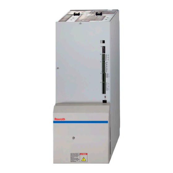
Summary of Contents for Bosch Rexroth Diax 04 HVE
- Page 1 Electric Drives Linear Motion and and Controls Hydraulics Assembly Technologies Pneumatics Service Rexroth Diax 04 R911320339 Edition 01 HVE and HVR 2nd Generation Power Supply Units Instruction Manual...
- Page 2 Instruction Manual 03.2007 edition Copyright 2007 Bosch Rexroth AG Copying this document, giving it to others and the use or communication of the contents thereof without express authority, are forbidden. Offenders are liable for the payment of damages. All rights are reserved in the event of the grant of a patent or the registration of a utility model or design (DIN 34-1).
-
Page 3: Table Of Contents
Rexroth Diax 04 HVE/HVR Contents Contents Important Notes Safety Instructions ........................1-1 General Information......................... 1-1 Contact with Electrical Parts....................1-2 Handling and Assembly......................1-2 Dangerous Movements ......................1-2 Magnetic and Electromagnetic Fields ..................1-4 Hot Parts..........................1-4 Appropriate Use..........................1-4 Identification Type Code ............................ - Page 4 Contents Rexroth Diax 04 HVE/HVR X8, Control voltage supply..................... 5-14 X11, DC bus connection......................5-16 X12, Ground connection......................5-17 X13, Optional choke connection (only HVE) ................. 5-17 Installation........................... 5-19 General Information on How to Install the Drive Controller ........... 5-19 Sizing of Enclosure and Control Cabinet................
-
Page 5: Important Notes
• If these documentations contain some information you do not understand, it is absolutely necessary that you ask Bosch Rexroth for explanation before you start working on or with the devices. -
Page 6: Contact With Electrical Parts
Important Notes Rexroth Diax 04 HVE/HVR Contact with Electrical Parts High electrical voltage! Danger to life, electric shock and severe bodily injury! • Follow general construction and safety regulations when working on power installations. • Before switching on the device, the equipment grounding conductor must have been... - Page 7 Rexroth Diax 04 HVE/HVR Important Notes Dangerous movements can occur immediately after equipment is switched on or even after an unspecified time of trouble-free operation. The monitoring in the drive components will normally be sufficient to avoid faulty operation in the connected drives. Regarding personal safety, especially the danger of bodily harm and material damage, this alone cannot be relied upon to ensure complete safety.
-
Page 8: Magnetic And Electromagnetic Fields
Important Notes Rexroth Diax 04 HVE/HVR Magnetic and Electromagnetic Fields Health hazard for persons with heart pacemakers, metal implants and hearing aids in proximity to electrical equipment! • Persons with heart pacemakers and metal implants are not permitted to enter following... -
Page 9: Identification
Rexroth Diax 04 HVE/HVR Identification Identification Type Code Note: The following figures illustrate the basic structure of the type codes. Your sales representative will help you with the current status of available versions. HVE 02.2 - W018N Example: Product Line... -
Page 10: Hvr
Identification Rexroth Diax 04 HVE/HVR HVR 02.2 - W010N Example: Product Line Design Cooling mode Air, internal (with built-in blower) Nominal power 10 kW 25 kW 45 kW Other design none hvr_typenschluessel_en.fh7 Fig. 2-2: Type code HVR Type Plate Device type HVE03.2-W030N... -
Page 11: Ratings And Dimensions
Rexroth Diax 04 HVE/HVR Ratings and Dimensions Ratings and Dimensions HVE02.2- HVE03.2- HVE03.2- HVE04.2- HVE04.2- Description Symbol Unit W018N W030N W030L W075N W075L listing according UL-standard (UL) UL 508 C listing according CSA-standard (UL) Canadian National Standard(s) C22.2 No. 14-05... -
Page 12: Hvr
Ratings and Dimensions Rexroth Diax 04 HVE/HVR HVE02.2- HVE03.2- HVE03.2- HVE04.2- HVE04.2- Description Symbol Unit W018N W030N W030L W075N W075L power dissipation at continuous current I and continuous DC out_cont 1251 1855 1855 3125 3125 Diss_cont bus power P respectively (UL) - Page 13 Rexroth Diax 04 HVE/HVR Ratings and Dimensions Description Symbol Unit HVR02.2-W010N HVR02.2-W025N HVR03.2-W045N pollution degree (UL) Use in a pollution degree 2 environment maximum ambient temperature with °C amax nominal data (UL) maximum ambient temperature with °C amax_red reduced nominal data (UL)
- Page 14 Ratings and Dimensions Rexroth Diax 04 HVE/HVR Distances air intake air outlet mounting surface in control cabinet distance top distance bottom Fig. 3-4: Air intake and air outlet at drive controller DOK-DIAX04-HVE+HVR*UL*-IB01-EN-P...
-
Page 15: Reference Documentation
Rexroth Diax 04 HVE/HVR Reference Documentation Reference Documentation Overview Title Type of documentation Document typecode DIAX04 HDD and HDS Drive Controllers Project Planning Manual DOK-DIAX04-HDD+HDS**G2-PRxx-EN-P Generation "List of Connecting Cables for DIAX04 and Selection lists DOK-CONNEC-CABLE*STAND-AUxx-EN-P ECODRIVE03" "LWL - Handling"... - Page 16 Reference Documentation Rexroth Diax 04 HVE/HVR DOK-DIAX04-HVE+HVR*UL*-IB01-EN-P...
-
Page 17: Instructions For Use
Rexroth Diax 04 HVE/HVR Instructions for Use Instructions for Use Overcurrent Protection Branch circuit protection has to be provided externally according to the maximum values (voltage and current or voltage and percent of FLA of the fuses [FLA: Full Load Ampacity]). -
Page 18: Wiring Diagram (Supply Unit Hvr)
Instructions for Use Rexroth Diax 04 HVE/HVR Wiring Diagram (Supply Unit HVR) mains ground connection control cabinet connecting clamps main switch control voltage connection distributor clamps fuse shielded cable power connection to the motors earth rail shielded control cabinet compartment or intermediate panel B02EMV.fh7... -
Page 19: Connection Diagram
Rexroth Diax 04 HVE/HVR Instructions for Use Connection Diagram 3 x AC 380 - 480 V bridged at 50 - 60 Hz delivery control voltage supply bridged at delivery power supply power supply & communication with auxiliary HVE02.2, HVE03.2 and modules (HZN, bleeder, etc.) - Page 20 Instructions for Use Rexroth Diax 04 HVE/HVR mains input HZF01.1-W0xxN 3 x AC 380 - 480 V 50 - 60 Hz Combining filter U4 V4 W4 X8/X8a U1 V1 KDxx Cu lead V2 W2 control voltage to the central supply...
-
Page 21: X0, Additional Component Bus
Rexroth Diax 04 HVE/HVR Instructions for Use X0, Additional component bus Terminal X0 Ap_X0.fh7 Fig. 5-5: Terminal X0 (condition as supplied with connectors) Design Type Number of poles Type of design screw terminal 2 x 10 bushing at connector Fig. 5-6:... -
Page 22: X1, Connection For Integrated Bus Connections From Neighboring Device
Instructions for Use Rexroth Diax 04 HVE/HVR X1, Connection for integrated bus connections from neighboring device Terminal X1 hve_X1 Fig. 5-9: Terminal X1 Design Type Number of poles Type of design ribbon cable connector pins at device ribbon cable bushing bushing at ribbon cable Fig. - Page 23 Rexroth Diax 04 HVE/HVR Instructions for Use Terminal assignment R01hva1B.fh7 Fig. 5-14: Terminal assignment X3 The DC bus brake switching is activated via plug-in terminal X3 and the mains contactor in the power supply unit is switched: If input “ZKS" is open, the DC bus short circuit is activated.
-
Page 24: X4, Control Voltages
Instructions for Use Rexroth Diax 04 HVE/HVR The power of the DC bus brake resistor is needed for the calculation of Number of switching actuations the permissible number of switching actuations: HVE02 HVE03 HVE04 HVR02 and HVR03 1000 W 1500 W... -
Page 25: X5, Mains Connection
Rexroth Diax 04 HVE/HVR Instructions for Use Terminal assignment +15 VM max. 100 mA 0 VM -15 VM shield +24 VL max. 2 A 0 VL R02hva1B.fh7 only for HVE Fig. 5-21: Terminal assignment X4 Control voltages 24 VL and ±15 VM can be tapped off of terminal strips X4/1…X4/6. - Page 26 5-10 Instructions for Use Rexroth Diax 04 HVE/HVR Fig. 5-23: Terminal X5 with HVE04.2 Design Type Number of poles Type of design screw terminal 1 x 4 bushing at device Fig. 5-24: Design Connection cross section Device Cross section Cross section...
-
Page 27: X6, Acknowledging The Power Supply Unit Mains Contactor
5-11 Rexroth Diax 04 HVE/HVR Instructions for Use X6, Acknowledging the power supply unit mains contactor Terminal X6 hvr_X6.fh7 hve_X6.fh7 Fig. 5-28: Terminal X6 Design Type Number of poles Type of design screw terminal 1 x 4 for HVR bushing at connector 1 x 6 for HVE Fig. -
Page 28: X7, Ready-To-Operate And Other Messages
5-12 Instructions for Use Rexroth Diax 04 HVE/HVR Note: The indicated voltages have to refer to potential ground. "Acknowledge power ON" At output acknowledge power ON it can be queried as to whether the mains contactor in the supply unit is on or not. The contact is closed if the mains contactor is on. - Page 29 5-13 Rexroth Diax 04 HVE/HVR Instructions for Use Terminal assignment ready-to- operate power voltage OK prewarning 1) braking resistor prewarning 1) only with HVE, not with HVR and HZS R04hva1b.fh7 Fig. 5-36: Terminal assignment X7 The terminal X7 contains outputs Description •...
-
Page 30: X8, Control Voltage Supply
5-14 Instructions for Use Rexroth Diax 04 HVE/HVR Power supply in order (UD) The UD contact acknowledges that the power supply is in working order. It opens in the event of the following faults: • mains fault • DC bus voltage is smaller than the permissible minimum value... - Page 31 5-15 Rexroth Diax 04 HVE/HVR Instructions for Use Connection cross section Cross section Cross section Wire size single-core multi-core in AWG [mm²] [mm²] gauge No.: 0,2...4,0 0,25 - 4,0 24...10 Fig. 5-40: Connection cross section Tightening torque 0,5 Nm Terminal assignment...
-
Page 32: X11, Dc Bus Connection
5-16 Instructions for Use Rexroth Diax 04 HVE/HVR X11, DC bus connection Terminal X11 DC bus connection X11 Max.Drehmoment/Torque: U,V,W, =2Nm hve_X11.fh7 Fig. 5-42: Terminal X11 Design Type Number of poles Type of design terminal block screw terminal for ring cable lug M5 Fig. -
Page 33: X12, Ground Connection
5-17 Rexroth Diax 04 HVE/HVR Instructions for Use X12, Ground connection Terminal X12 grounding bracket Max.Drehmoment/Torque: U,V,W, =2Nm hve_X12.fh7 Fig. 5-46: Terminal X12 Screw terminal Design 3 Nm Tightening torque The ground connection to the drive controllers is double: • rear panel of device and mounting rail •... - Page 34 5-18 Instructions for Use Rexroth Diax 04 HVE/HVR Design HVE02/HVE03 HVE04 screw terminal screw terminal Type Number of poles screw terminal for ring multi-core with Type of design cable lug M5 connector sleeve or single-core 10...25 16...50 Cross section [mm Tightening torque 2,5...3,0...
-
Page 35: Installation
5-19 Rexroth Diax 04 HVE/HVR Instructions for Use Installation General Information on How to Install the Drive Controller Damage can be caused to the drive controller or circuit boards if electrostatic charging present in people and/or tools is discharged across them. -
Page 36: Sizing Of Enclosure And Control Cabinet
5-20 Instructions for Use Rexroth Diax 04 HVE/HVR Sizing of Enclosure and Control Cabinet Control Cabinet with Multiple-Line Structure Note: Particular attention should be paid to the maximum allowed air intake temperature of components when they are arranged in multiple lines in the control cabinet. Where necessary, cooling air guides are to be provided with blowers specially used for this purpose. - Page 37 5-21 Rexroth Diax 04 HVE/HVR Instructions for Use correct incorrect Cooling system Cooling system warm cold warm cold Air duct electronic electronic equipment equipment Cabinet Cabinet Eb0001f1.fh7 Fig. 5-54: Arranging the cooling unit on the control cabinet incorrect correct control cabinet...
- Page 38 5-22 Instructions for Use Rexroth Diax 04 HVE/HVR DOK-DIAX04-HVE+HVR*UL*-IB01-EN-P...
-
Page 39: Appendix
Rexroth Diax 04 HVE/HVR Appendix Appendix Discharging of DC Bus Capacitors In the drive system Rexroth IndraDrive capacitors are used in the DC bus as energy stores. In the drive controllers and particularly in the supply units such capacitors have already been integrated. -
Page 40: Discharging Device
Appendix Rexroth Diax 04 HVE/HVR Discharging Device Lethal electric shock caused by live parts with more than 50 V! Before touching live parts check in any case whether ⇒ the voltage between the DC bus terminals L+ and L- WARNING... - Page 41 Rexroth Diax 04 HVE/HVR Index Index Connection Diagram HVE 5-3 HVR 5-4 Connections 5-1 control cabinet with multiple-line structure 5-20 Control voltages 5-9 cooling units 5-20 DC bus connection 5-16 Dimensions HVE 3-1 HVR 3-2 dripping or sprayed water 5-20...
- Page 42 Index Rexroth Diax 04 HVE/HVR Wiring Diagram Supply Unit HVE 5-1 Supply Unit HVR 5-2 X0, Additional component bus 5-5 X1, Connection for integrated bus connections from neighboring device 5-6 X11, DC bus connection 5-16 X12, Ground connection 5-17 X13, Optional choke connection (only HVE) 5-17...
- Page 44 Bosch Rexroth AG Electric Drives and Controls P.O. Box 13 57 97803 Lohr, Germany Bgm.-Dr.-Nebel-Str. 2 97816 Lohr, Germany Phone +49 (0)93 52-40-50 60 +49 (0)93 52-40-49 41 service.svc@boschrexroth.de www.boschrexroth.com Printed in Germany...
Need help?
Do you have a question about the Rexroth Diax 04 HVE and is the answer not in the manual?
Questions and answers