Table of Contents
Advertisement
Quick Links
Advertisement
Table of Contents
Troubleshooting

Subscribe to Our Youtube Channel
Related Manuals for Fastjet A470 Series


Summary of Contents for Fastjet A470 Series
- Page 1 Inkjet Printer A470 Series Operation Manual May 11 2020 Edited V1.1...
-
Page 2: Table Of Contents
Content 1. Safety Guidelines ------------------------------ 1.1.Safety warning ------------------------------------------------------------- 1.2.Safety prevention --------------------------------------------------------- 1.3.Use --------------------------------------------------------------------------- 1.4.Handling --------------------------------------------------------------------- 1.5.Responsibility -------------------------------------------------------------- 2. Instructions -------------------------------------- 2.1.Specifications -------------------------------------------------------------- 2.2.Appearance overview ---------------------------------------------------- 2.3.Control Panel -------------------------------------------------------------- 2.4.Hydraulic diagram -------------------------------------------------------- 2.5.Printhead -------------------------------------------------------------------- 2.6.Ink Core --------------------------------------------------------------------- 2.7.Main Screen ---------------------------------------------------------------- 2.8.Menu Analysis ------------------------------------------------------------- 2.8.1.Messages ----------------------------------------------------------------------... - Page 3 3.3.Stop Jet -------------------------------------------------------------------- 3.3.1.Stop Jet and Clean --------------------------------------------------------- 3.3.2.Stop&Clean (Power off during the inkjet running) ------------------ 3.3.3.Stop and Clean (long-term stop ) --------------------------------------- 3.4.Create Message --------------------------------------------------------- 3.4.1.Create a sample message ----------------------------------------------- 3.5.Create/Edit User Field ------------------------------------------------- 3.5.1.Time User Field -------------------------------------------------------------- 3.5.2.Additional remarks for time user field --------------------------------- 3.5.3.Barcode User Field ---------------------------------------------------------...
-
Page 4: Safety Guidelines
1. Safety Guidelines 1.1. Safety warning • Maintenance of this equipment must be performed by a maintenance professional. • When the printer is connected to the power supply and related circuits, a lethal voltage is generated. Non-professionals cannot open the circuit compartment, and cannot check and repair the circuit system. -
Page 5: Handling
• It is recommended to use the original consumables (including inks, solvents, cleaning agents, maintenance products, etc.) of the printer. You must obtain the Material Safety Data Sheet (MSDS) from the dealer and read and follow them carefully. Otherwise the consequences will be borne by the user. -
Page 6: Instructions
2. Instructions 2.1. Specifications ELECTRICAL SPECIFICATIONS Voltage 110V-240VAC Frequency 50Hz-60Hz Energy consumption 120(W)maximum value WEIGHT Net weight 22kg DIMENSIONS Cabinet 390L*295W*540H Printhead diameter 41mm Printhead length 260mm Nozzle size 60um Umbilical length 2700mm ENVIRONMENT SPECIFICATIONS Operating temperature 5℃ to 45℃ Ambient temp replacing rate 10℃... -
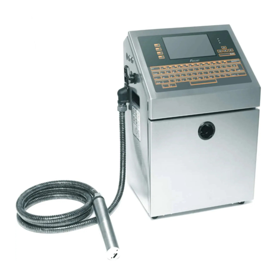
Page 7: Appearance Overview
2.2. Appearance overview Right View Front View Left View Introduction : 1. Upper: Electronics Compartment 、Control Panel 2. Lower: Ink Compartment 3. Connector Panel 4. Umbilical 2.3. Control Panel Indication LED Shortcut keys Cursor control Confirm button Delete button Diagnosis Screen Input Method Switch Page 4... -
Page 8: Hydraulic Diagram
2.4. Hydraulic diagram 1. When the valve is energized, I-O will open and I-N will close. 2. When the valve is de-energized, I-N will open and I-0 will close. Main ink cycle —— Consumable adding system —— Viscosity detection system ——... -
Page 9: Printhead
2.5.Printhead Last Chance Filter Nozzle connector Nozzle Charge Electrode Phase Detector Deflection Plate Gutter Pipe 2.6. Ink Core * Exhaust Air Switch Condenser Cover Suction pipe Gear Pump Drain Pipe * Exhaust Vent Plug Ink Core(Left View) Ink Core(Right View) * Please remove the exhaust vent plug and turn on exhaust air switch before use. -
Page 10: Main Screen
2.7.Main Screen The main screen is the default screen after the printer powered on: Instructions: Main Menus. Shortcut function keypad. The name and content of the current message, it’s a WYSIWYG message viewer, the content of which is consistent with the content printed by the printer. -
Page 11: Menu Analysis
2.8. Menu Analysis 2.8.1. Messages Used to create new messages. Used to edit saved messages. Used to select and recall the stored messages , which is equivalent to the “F2 Select Message” on the main screen. Used to set the parameters of current message, which is equivalent to the “F3 Message Parameters”... -
Page 12: User Fields
Used to select fonts , which is equivalent to the shortcut “F1” in message editor. Used to insert user fields into current message, which is equivalent to the “F2” in message editor. Used to save messages, which is equivalent to the “Shift + F1 ” in message editor. -
Page 13: Print
2.8.4. Print Used to control the printing Used to trigger printing manually Used to set the print modes. Used to set the photocell mode. Used to set the photocell signal blocking time and mode. It is used to set the reverse print mode. 2.8.5.Password Enter user password for advanced operating authority. -
Page 14: System
Open the Set Password Level menu. This has options for the Main Screen and each of the menus. You can set “On” or “Off” for each option available in the menu. “Off” doesn’t have password protection. Enter maintain password for maintenance authority. Enter a new maintain password to change maintain password. -
Page 15: Config
(10) Turn on/turn off each valve and main pump separately. (11) Set gutter mode Continuous or Intermittent. (12) Drain the Ink System (13) Wash nozzle automatically (14) Ink system clean 2.8.7.Config Set nozzle temperature(0 to 40 ℃) Set pump pressure (0 to 450 Pa) It is able to set the viscosity of ink manual/auto. -
Page 16: Date
(10) Set the Real Time Clock(RTC) in the printer to the local time and date. (11) Pump zero adjustment. (12) Set EHT value of each grade (13) Select the ink type. (14) Set character width ratio/print delay ratio/Internal Interval ratio/ External Interval ratio. -
Page 17: Printer Operation
3. Printer Operation 3.1. Commission Printer needs to be filled with ink and exhaust air before use. 1. Open the lower cabin door, pull out the ink system, and fill 750ml of ink into the mixer tank with a beaker in the order of A. B.* C. D., as shown in figure: ... - Page 18 a. Enter the DEBUG function in SYSTEM menu. b. Open the Printhead cover, place a container under the head c. Turn on “Pump", "Valve 6", "Valve 11", and "Valve 12" in turn, and keep them on for three minutes. c. After approximately 3 minutes of operation, open "Valve 7”. d.
-
Page 19: Start The Printer
3.2. Start The Printer 3.2.1. Start Jet 1. Connect the printer to an appropriate power source. 2. Open the printer head cover, check various components in the printhead, and check that various components are clean and dry. 3. Put on the printhead cover, press the power button at the right side of the printer, and wait for the screen to enter the main operation interface 4. -
Page 20: Inkjet Observation
3.2.2. Inkjet Observation Side View Inkjet Charge Nozzle Electrode The inkjet is at the central position of the gutter pipe Front View The inkjet is about 1/4 of the right side of the gutter pipe Nozzle Charge Electrode Page 17... -
Page 21: Drops Observation
3.2.3. Drops Observation The drops are generated after printer has started normally. It directly affects the printing effect and printing durability. Good drops roughly depend on the following three factors: Appropriate and stable pressure Correct ink viscosity Correct modulation value The observation method is as follows: 1. -
Page 22: Stop Jet
3.3. Stop Jet 3.3.1. Stop Jet and Clean 1.Press F1 button, it lasts for about 4 minutes, the screen is as follows: 2. During cleaning after shutdown, remove the Printhead cover and observe if the printhead is dirty. If needed clean the printhead with the necessary cleaning agent. 3. -
Page 23: Create Message
1. Enter the MESSAGE menu,select New Message, confirm and enter the screen as shown in the following figure: 2. Input file name TEST, then press enter key, as shown in the following figure: 3. Press repeatedly. When the editing state is displayed as "16 High " then input “FastJet". Page 20... - Page 24 4. Press to select the “R” User Field (refer to 3.5.7 Logo), press the Enter key to insert, as shown below: In the editing interface, the function is “ Insert User Field ”. 5. After the content is entered, press the “ Shift + F1” button and confirm. *...
-
Page 25: Create/Edit User Field
3.5. Create/Edit User Field 3.5.1. Time User Field Follow the steps below to create: 1.Enter the USER FIELD menu,select New User Field, as shown in the figure below: 2. Input a file name, switch “Attr” to “Time” then confirm , as shown in the figure below: 3. -
Page 26: Additional Remarks For Time User Field
3.5.2. Additional remarks for time user field Definition of Time User Field Code Definition Code Monday to Sunday Year Month Hour Minute Second Week Alpha Year Code Alpha Month Code Alpha Day Code Alpha Hour Code Alpha Minute Code 1. Actual printing date and time = system current time + number of days of Expiry term. -
Page 27: Barcode User Field
3.5.3. Barcode User Field The standards of barcode supported by the type include: QR Code (Figure 1), Data Matrix (Figure 2), Code39 (Figure 3), Code128 (Figure 4), EAN8 (Figure 5), EAN13 (Figure 6), EAN128 (Figure 7) 1. Enter the USER FIELD menu,select New User Field, as shown in the figure below: 2. -
Page 28: Additional Remarks For Barcode User Field
3.5.4. Additional remarks for Barcode User Field 1. The size (Height x Width) supported by Data Matrix include 10x10, 12x12, 14x14, 16x16, 18x18, 20x20, 22x22, 24x24, 26x26, 32x32, 8x18, 8x32, 12x26, 16x36, 16x48. 2. The size (height x width) supported by QR Code include 21x21, 25x25, 29x29, 33x33. -
Page 29: Counter User Field
3.5.5. Counter User Field 1. Enter the USER FIELD menu,select New User Field, as shown in the figure below: 2. Input a file name, switch “Attr” to “Counter” then confirm , as shown in the figure below: Instructions of each items refer to “ 3.5.6 Instructions for items in the Counter ”. ... -
Page 30: Instructions For Items In The Counter
3.5.6. Instructions for items in the Counter 1. Start value : Start value of the counter. 2. Current value: Set the current value of current counter 3. End value : End value of the counter 4. Reset value : Value to be reset when the function of "Reset Counter" of the Photocell 2 is used. -
Page 31: Logo User Field
3.5.7. Logo User Field The Logo User Field can create the customized logo of maximum 34 dots height. 1. Enter the USER FIELD menu,select New User Field, as shown in the figure below: 2. Input a file name, switch “Attr” to “Counter” then confirm , as shown in the figure below: 3. - Page 32 4. After drawing, press the "ESC" key to return to the main menu, press the arrow keys to move left or right to the "Editor" menu, you can set the pattern size, as shown below: 5. After setting the size of the pattern, press the "enter" key to confirm the size, then enter the "Editor"...
-
Page 33: Code User Field
3.5.8 Code User Field This function can integrate multiple User Fields ( Time, counter and text ) in to generate a code. 1. Enter the USER FIELD menu,select New User Field, as shown in the figure below: 2. Input a file name, switch “Attr” “Code” then press Enter to confirm , When the cursor hovers between Content 1 and Content 6, press F2 to insert in sequence the User Fields to be combined. -
Page 34: External Data User Field
3.5.9 External data User Field The function can receive the external data predefined by the user and print them in sequence. The preparation steps are as follows: 1. Enter the USER FIELD menu,select New User Field, as shown in the figure below: 2. -
Page 35: Message Parameters
3.6 Message Parameters 3.6.1 Modify message parameters In the main screen, press the F3 key to enter the interface to modify parameter of current message , as shown in the figure; More detail about Message Parameters, please read the following table: Parameter Range Function... -
Page 36: Print Mode Setting
3.7 Print Mode Setting 3.7.1 Single Printing Mode The mode is commonly used for beer, beverage, food, daily necessities and other familiar industries, one trigger one printing. 1. Select PRINT menu and press Enter to call out the following sub menus: 2. -
Page 37: Continuous Printing Mode
3.7.2 Continuous Printing Mode The mode is commonly used for building materials, pipe, steel material and other industries. The common feature is continuous processing, messages automatic interval printing. 1. Select PRINT menu and press Enter to call out the following sub menus: 2. -
Page 38: Times Printing Mode
3.7.3 Times Printing Mode In this mode you can set the specific numbers of printing per trigger. 1. Select PRINT menu and press Enter to call out the following sub menus: 2. Enter Continuous Print sub menu , Switch the "Continuous Mode" to “Times"... -
Page 39: Measure Mode
3.7.4 Measure mode The mode is commonly used in the wire cable, pipe and other industries requiring labelling of number of meters , the encoder must be used. 1. Select PRINT menu and press Enter to call out the following sub menus: 2. -
Page 40: Traverse Printing Mode
3.7.5 Traverse Printing Mode The mode is commonly used in electronics, label printing, egg and other industries, and provides highly-efficient production mode for the array type printing. In this mode you can set the specific numbers of printing per trigger. 1. - Page 41 c. Print Reset : After reset, the printer will start to print forward direction d. Print Times : use to set the print times after trigger. e. Forward Reverse : If set it to OPEN, the Forward direction will pint Reverse-off and vice versa.
-
Page 42: Trouble Shooting And Maintenance
4. Trouble Shooting and Maintenance 4.1 Diagnostic screen Diagnostic screen can be entered into any time by press the “i” key located at the left bottom keyboard. 1. Ink : real time pressure of Ink. It is generally 300-350 under normal startup mode. -
Page 43: Faults And Warning Icons
4.2 Faults and Warning Icons 4.2.1 Fault Icons Remedial Action Icon Name Cause Check the ink system with Ink leak the help of engineer. Mixer Add ink until the icon Tank Solvent vaporization disappears. Empty Take V2 down and clean it Valve Clogging up with special cleaner. -
Page 44: Warning Icons
4.2.2 Warning Icons Icon Name Instructions for warning Add solvent. Please contact maintenance engineer if the icon still Low ink level appears after adding. Add ink. Please contact maintenance Low solvent level engineer if the icon still appears after adding. The head cover is opened, the printer Print head cover is cannot print, the warning will... -
Page 45: Troubleshooting
4.3 Troubleshooting • Turn on the power supply, there is no display on screen. Reason Solution No voltage of the power supply Check the power supply and related fuse • Poor jet printing character quality or incomplete character Reason Solution The printhead is too far from the Adjust the distance between the printhead product... -
Page 46: Wash Nozzle
4.4 Wash Nozzle When the nozzle is blocked, manual cleaning is required for the function. The operation procedures are as follows: 1. Go to SYSTEM menu,select and perform Nozzle Flush program. 2. After the program is started, manually clean the position shown in the following figure with cleaning agent. -
Page 47: Drain
4.6 Drain Go to the "System" menu, select “System Flush Purge" and press the "enter" key to confirm. 1. First pull out the OUT port of the ink and connect it to the special waste bottle. 2. Invert the pressure buffer. 3. -
Page 48: Sensor And Encoder Wiring Diagram
4.7 Sensor and Encoder Wiring Diagram 4.7.1 Sensor Diagram 4.7.2 Encoder Diagram Page 45... - Page 49 Fastjet reserves the right to modify the technical characteristics of the product without prior notice. Manufacturer Name: Shanghai Fastjet Electronic Equipment Co., Ltd. A d d . : No.18 Building, Lane 699, Zhangwenmiao Road, Fengxian District, Shanghai Te l : 00 86 21-57484418 Fax: 00 86 21-57484498 http://www.fast-jet.com...
Need help?
Do you have a question about the A470 Series and is the answer not in the manual?
Questions and answers