Table of Contents
Advertisement
Quick Links
Advertisement
Table of Contents
Troubleshooting

Subscribe to Our Youtube Channel
Related Manuals for Fastjet A400 Series


Summary of Contents for Fastjet A400 Series
-
Page 2: Table Of Contents
Contents Chapter 1. Product Overview ............1.1 Main parts ..............1.2 Control Panel ..............1.3 Print Head ..............1.4 Ink Compartment ............. 1.5 Main Screen ..............1.6 Menu Description ............. 1.6.1 Message menu ............1.6.2 Editor ..............1.6.3 User Fields ............. - Page 3 2.3.3 Split Point Observation ..........2.4 Turn off the Printer ............2.4.1 Clean Stop Normally ..........2.4.2 Clean stop (Power failure during the usage) ....2.4.3 Clean stop (long term shutdown) ......... 2.5 Message ............... 2.5.1 Create a Message ........... 2.6 User Field ..............
-
Page 4: Chapter 1. Product Overview
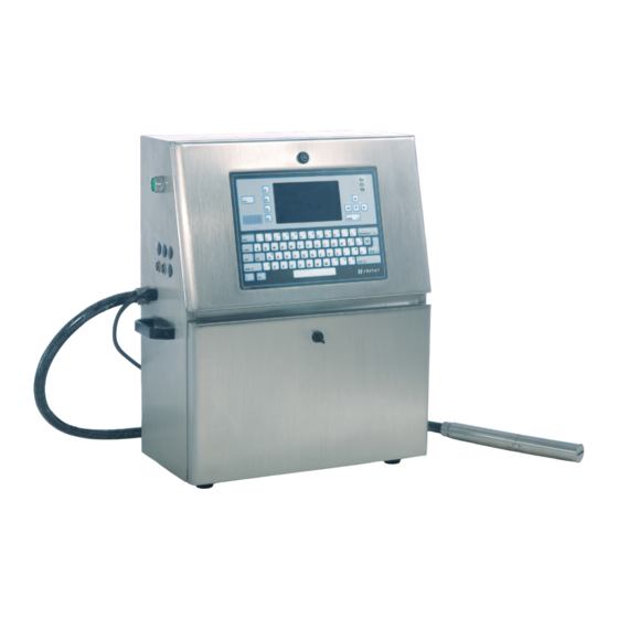
Chapter 1. Product Overview 1.1 Main parts Major parts of A400 Inkjet Printer are as follows: Figure 1-1. Main parts of the printer 1. Main Power Switch 2. Connector Panel 3. Umbilical 4. Print Head 5. Ink Compartment 6. Control Panel 7. -
Page 5: Control Panel
1.2 Control Panel Figure 1-2: Control Panel 1. Function Keys 2. Information Key 3. Keypad 4. Arrow Keys 5. Status LEDs 6. Display... -
Page 6: Print Head
1.3 Print Head Figure 1-3: Print Head 1. Front Cover of Print Head 2. Electrode of High Voltage Deflection Plate 3. Phase Detector 4. Charge Electrode 5. Heating Block Assembly 6. Rear Cover of Print Head 7. Valves 8. Nozzle Assembly 9. -
Page 7: Ink Compartment
1.4 Ink Compartment Figure 1-4: Ink Compartment 1. Ink Tank 2. Solvent Tank 3. Cleaning Pump 4. Cleaning Filter 5. Filter before print head 6. Primary Filter 7. Pressure Buffer 8. Drainage Pipe 9. Filter before pump 10.Valves... -
Page 8: Main Screen
1.5 Main Screen Figure 1-5: Main Screen 1. Menus 2. Function Keys 3. Printer Status 4. the Name and the Content of the Message 5. Product Counter 6. Fault and Alarm Icons This screen displays the following elements: ● The function key controls. ●... -
Page 9: Menu Description
1.6 Menu Description 1.6.1 Message menu Message menu Function Open the New Message interface to create a new New Message message. Edit Message Edit a selected internal message. Select Message Select a message to print. Message Parameters Change parameter of the current print message Delete Message Delete the selected internal message. -
Page 10: User Fields
Editor menu Function Set Logo Size Change the size of the logo. Save the logo to the memory and keep the editor screen Save Logo open. Save and Exit Save the logo to the memory and exit the editor screen. Clear Logo Removes the edited logo. -
Page 11: Password
1.6.4 Password Password menu Function Enter user password for advanced operating Enter User Password authority. Enter a new user password to change user Change User Password password. Open the Set Password Level menu. This has options for the Main Screen and each of Set Password Levels the menus. -
Page 12: System
1.6.5 System System menu Function Start the ink jet. A flush and bleed sequence is performed to prevent unstable ink line while Clean Start Jet ejecting from nozzle. Quick Start Jet Quick start the ink jet without a flushing sequence. Stop the ink jet. -
Page 13: Configuration
1.6.6 Configuration Configure menu Function Set nozzle temperature(0 to 40 ℃) Heater Set Point Set Running Pressure Set pump pressure (0 to 450 Pa) VMS Calibration It is able to set the viscosity of ink manual/auto. Modulation Set Level Set modulation value. Phase Charge Set Set phase charge value. -
Page 14: Data
1.6.7 Data Data menu Function Status Display each of current status of the printer. All current operational monitoring data of the Diagnostic Screen printer which are conductive to diagnose malfunctions. Product Counter It can be used to reset counter. Software No. Display software version. -
Page 15: Specifications
1.7 Specifications 1.7.1 Electrical Specification The electrical specifications of the printer are shown in Table 1-9. Voltage 100V AC - 240V AC Frequency 50Hz to60Hz Power Consumption 90 watts Maximum Table 1-9. Electrical specifications 1.7.2 Weight The net weight specifications of the printer are shown in Table 1-10. Net Weight 27kg Table 1-10. -
Page 16: Chapter 2. Printer Operation
Chapter 2. Printer Operation 2.1. Introduction This chapter provides the procedures to do the following tasks: ● Installation method used for the first time ● Start print ● Turn off the printer ● Manage message ● Manage user field ● Print configuration 2.2. - Page 17 Figure2-1. How to inject ink into the mixer tank. Notes Stop injecting ink once the Main Screen display the Mixer Tank Full icon. Stop injecting ink once the Diagnosis Screen Mixer High turn to ‘ON’. Note Please inject ink and solvent into ink tank and solvent tank separately after ink injection successful.
-
Page 18: Exhaust The Air Of Pipe System
2.2.2 Exhaust the air of Pipe System Exhaust the air of the pipe system after manual ink injection. The procedures are as follow: 1. Select the System menu using the Left/Right arrow key. Press the Enter key. 2. Select the Debug menu and then press the Enter key. The interface is as follow. -
Page 19: Start Print
2.3 Start Print 2.3.1 Start Jet To start the printing process, the following operations are required: 1. Make sure that the electrical supply for the printer is available. 2. Open the front cover of the print head, check on the components inside the print head make sure that all components are clean and dry. -
Page 20: Ink Line Observation
2.3.2 Ink line Observation The ink spouts through the nozzle, and then recycles by the gutter after jet starting. Side View: Figure 2-5. Side View of Ink line Front View: Figure 2-6. Side View of Ink line... -
Page 21: Split Point Observation
2.3.3 Split Point Observation The state of split point will influence the print effects and stability. The quality of the split point is depends on these three points below: Appropriate and stable ink pressure. ■ Accuracy ink VMS. ■ Proper modulation configuration. ■... -
Page 22: Turn Off The Printer
2.4 Turn off the Printer 2.4.1 Clean Stop Normally 1. Press the F1 key to start the jet stop sequence. The default sequence is Clean Stop. The clean stopping sequence takes approximately two minutes. The interface is as follow: Figure 2-9. Stopping interface. 2. -
Page 23: Message
2.5 Message 2.5.1 Create a Message Do the following tasks to create a message: 1. Use the arrow keys to open Message menu. Select New Message. The New Message dialog box appears (See Figure 2-11). Figure 2-11. New Message Dialog Box 2. -
Page 24: User Field
2.6 User Field 2.6.1 Time 2.6.1.1 Create a Time user field Do the following tasks to create a time user field: 1. Select User Field menu. Select New User Field and press Enter key. The New User Field dialog box appears(See Figure 2-13). Figure 2-13 New User Field Dialog Box. -
Page 25: Two-Dimensional Code And Barcode
2.6.1.2 Time User Field Clock Information The following table lists the clock codes required to define the clock information. code Definition Day number(1 to 7) Year Month Date Hour Minute Second Week Number Day of year Table 2-1. Clock codes and definitions. 2.6.2 Two-dimensional Code and Barcode The Printer support these types of two-dimensional code and barcode. -
Page 26: Counter
2.6.3 Counter The counters ( Serializers ) Do the following tasks to add counter user field in User Fields. 1. Select User Field menu. Select New User Field and press Enter key. The New User Field dialog box appears. 2. Enter a name for the Counter User Field. 3. -
Page 27: Logo
2.6.4 Logo Do the following tasks to add Logo user field in User Fields. 1. Select User Field menu. Select New User Field and press Enter key. 2. Enter a name for the Logo User Field. 3. Use the Left arrow key and Right arrow key to select Logo as the descriptions, and press the Enter key to open Logo Editor. -
Page 28: Multiple User Fields To Generate A Barcode
2.6.5 Multiple user fields to generate a barcode This function can make multiple user fields (only including clock, counter, text) to generate one barcode. Generation steps are as follow: 1. Select User Field menu. Select New User Field and press Enter key. 2. -
Page 29: Message Parameters
2.7 Message Parameters Message parameter decides the printing mode for Message, and can be set as follows: Parameter Scope Performance Set Message width, the smallest the font width is, the fastest the printing speed. For instance, when the font width is set as Font Width 1-255 1, the printing speed is the fastest. - Page 30 Editing Parameter Procedure: 1. Press the F3 key (only in main screen) to open the Message Parameter dialog box (See Figure 2-18 ). Figure 2- 18. Message Parameter dialog box 2. input the numerical value you need; 3. After setting all parameter values, press Enter to return to main menu screen.
-
Page 31: Print Configuration
2.8 Print Configuration The printer is configured through the Print menu. 2.8.1 Limited print times configuration This mode widely applied in beer, beverage food, daily use chemical and other industries. In general, photocell triggered once, printer print message one or several times which can set in Continuous Print menu. Do the following operations: 1. - Page 32 a. Print Enable menu. Figure2- 20. Print Control menu ● Select Print Enable option. ● Set the Shaft Encode to Internal option for a fixed line speed. Set to External option for use with a compatible shaft encoder where the line speed is variable. ●...
- Page 33 condition, the printer will print after triggered. ● Select Continuous Mode Close option, if you want print one time after triggered. Select Continuous Mode Times option, if you want print several times after triggered. ● Set print times after triggered. ●...
-
Page 34: Continuous Print
2.8.2 Continuous Print The message is printed repeatedly. This mode widely used in building material, pipe material and steel product and other industrials. Do the following operations to print continuous: 1. User the arrow keys to open Print menu. 2. If you want to use continuous print mode to print . You should set Print Enable, Continuous Print and Photocell Level menus. - Page 35 ● When Trigger Mode select Trigger. Once triggered the printer will print Continuous Time, unless the photocell level condition. When Trigger Mode select Gate. Only meet photocell level condition, the printer will print after triggered. ● Select Continuous Mode Open option. ●...
-
Page 36: Meter Mode
2.8.3 Meter Mode This mode widely used in cable pipe and other industrials where need identify meters. There must be a shaft encoder. The setting of this mode is as follow: 1. User the arrow keys to open Print menu. 2. -
Page 37: Reverse Mode
2.8.4 Reverse Mode This mode widely used to in electronic, label printing, egg and other industries. It provides the effective production for the array printing. To use Reverse Mode need to set: 1. User the arrow keys to open Print menu. 2. - Page 38 Figure2-29 . Continuous Print menu ● Do not need to set. ● Select Continuous Mode Reverse option. ● Do not need to set. ● Do not need to set. ● Do not need to set. c. Photocell Level menus. Figure2-30. Photocell Level Signal Block menus. ●...
- Page 39 ● Set the print delay when print forward direction. ● Set the print delay when print opposite direction. Note The print delay in message parameter is invalid in Reverse Mode ● Reset print. After reset, the printer will print forward direction. ●...
-
Page 40: Chapter 3. Trouble Shooting And Maintenance
Chapter 3. Trouble Shooting and Maintenance 3.1 Diagnostic screen Diagnostic screen can be entered into any time by press the “i” key located at the left bottom keyboard. The Diagnostic screen Figure 3-1. Diagnostic screen Meaning of major parameters: Ink:——Ink system (i.e. ink pump) operating pressure. It is generally 300-350 under normal startup mode. -
Page 41: Fault And Warning Icon
3.2 Fault and Warning Icon Fault Icons Icon Name Cause Remedial Action Check the piping system with the Ink leak help of engineer. Mixer Solvent Add ink until the icon disappears. Tank vaporization Empty Take V2 down and clean it up Valve Clogging with special cleaner. - Page 42 Warning Icons Icon Name Indication Printer is Ink jetting is running, printer is ready for running. printing. Printing stops. Ink jetting stops. Add ink. Please contact maintenance Low ink level engineer if the icon still appears after adding. Add solvent. Please contact maintenance Low solvent engineer if the icon still appears after level...
-
Page 43: Trouble Shooting
3.3 Trouble Shooting The Printer Does Not Start " Check the power supply and if the Printer is turned on. " Keyboard has echo sound but screen is off Please check the screen contrast. After restart the printer, press “Ctrl” + “L” and press enter when screen is clear. Poor printing quality "... -
Page 44: Nozzle Cleaning
3.4 Nozzle Cleaning 1. In the “System” menu select the “Nozzle Flush”. Figure 3-2. Nozzle Flush screen 2. When the “F1” function on the main screen showed “Stop Flus”, use cleaner wash the position of print header shown in flowing picture until the “F1”... -
Page 45: Ink Line Adjustment
3.5 Ink Line Adjustment " Left/Right adjustment Loose the 1 screw in the screen and move the “2” slightly can move the ink line left or right. " Up/Down adjustment Loose the 1 screw in the screen and move the “2” slightly can move the ink line up and down. -
Page 46: Draining Ink
3.6 Draining Ink 1. Unscrew the “OUT” port out and put it into the effluent bottle. 2. Inverse the pressure buffer. 3. In the “System” menu select the “Single Step”, open “Pump”, “Valve 6”, “Valve 11”, “Valve 12”, ink will be drained from the “OUT” port. -
Page 47: Pipe Cleaning
3.7 Pipe cleaning This operation is usually used to device maintain and change ink. The procedures are as follow: 1. Fill the mixer tank with the cleaner after ink in the tank was drained (refer to the Draining Ink). 2. In the “System” menu select the “Single Step”, open “Pump”, “Valve 6”, “Valve 11”, “Valve 12”,waiting for 10 minutes. -
Page 48: Shaft Encoder And Photocell Connection
3.8 Shaft Encoder and Photocell Connection 3.8.1 Photocell Connection 3.8.2 Shaft Encoder Connection ...
Need help?
Do you have a question about the A400 Series and is the answer not in the manual?
Questions and answers