Sign In
Upload
Download
Table of Contents
Contents
Add to my manuals
Delete from my manuals
Share
URL of this page:
HTML Link:
Bookmark this page
Add
Manual will be automatically added to "My Manuals"
Print this page
×
Bookmark added
×
Added to my manuals
Manuals
Brands
Fastjet Manuals
Printer
F500 Series
Operation manual
Fastjet F500 Series Operation Manual
Hide thumbs
1
Table Of Contents
2
3
4
5
6
7
8
9
10
11
12
13
14
15
16
17
18
19
20
21
22
23
24
25
26
27
28
29
30
31
32
33
34
35
36
37
38
39
40
41
42
43
44
45
46
47
48
49
50
51
52
page
of
52
Go
/
52
Contents
Table of Contents
Troubleshooting
Bookmarks
Table of Contents
Table of Contents
1 Safety Guidelines
Safety Warning
Safety Prevention
Use
Handling
Responsibility
2 Introduction
Appearance Overview
Control Panel
Printhead
F500 Series Printhead
F500Plus Series Printhead
Ink Core
Electronics Compartment
Main Screen
Menu Analysis
Print Data
User Field
Print Set
Ink System
Machine Set
F4 Password
W) User Defined
Photocell 1 Set
Photocell 2 Set
Specifications
3 Printer Operation
Commission(For F530 / F530Plus
Commission(For F550 / F550Plus
Start the Printer
Start Jet
Inkjet Observation
Drops Observation
Stop Jet
Stop Jet and Clean
Stop and Clean (Power off During Use of the Printer)
Stop and Clean (Long-Term Stop of Use)
Create Message
Create a Sample Message
Create/Edit User Field
Time User Field
Additional Remarks for Time User Field
Barcode User Field
Additional Remarks for Barcode User Field
Counter User Field
Instructions for Items in the Counter
Logo User Field
Code User Field
External Data User Field
Message Parameters
Modify Message Parameters and Contents
Print Mode Setting
Single Printing Mode
Continuous Printing Mode
Measure Mode
Traverse Printing Mode
Repeat Printing Mode
4 Maintenance
Diagnostic Screen
Failure and Warning Icons
Failure Icons
Warning Icons
Troubleshooting
Wash Nozzle
Ink Jet Alignment
Drain
Clean Ink System
Sensor and Encoder Wiring Diagram
Sensor Diagram
Encoder Diagram
Printer Stander
Advertisement
Quick Links
1
Troubleshooting
Download this manual
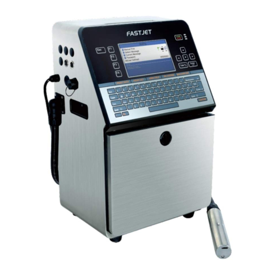
Inkjet Printer
FASTJET F500 Series
FASTJET F500Plus Series
Operation
Manual
Dec. 08
2018 Edited V1.3
th
Table of
Contents
Previous
Page
Next
Page
1
2
3
4
5
Advertisement
Table of Contents
Need help?
Do you have a question about the F500 Series and is the answer not in the manual?
Ask a question
Questions and answers
Related Manuals for Fastjet F500 Series
Printer Fastjet F550 Operation Manual
(52 pages)
Printer Fastjet F540 Series Operation Manual
(48 pages)
Printer Fastjet F560 Series Operation Manual
(48 pages)
Printer Fastjet A400 Series User Manual
(49 pages)
Printer Fastjet A470 Series Operation Manual
(49 pages)
This manual is also suitable for:
F500plus series
F530
F530plus
F550
F550plus
Table of Contents
Save PDF
Print
Rename the bookmark
Delete bookmark?
Delete from my manuals?
Login
Sign In
OR
Sign in with Facebook
Sign in with Google
Upload manual
Upload from disk
Upload from URL


Need help?
Do you have a question about the F500 Series and is the answer not in the manual?
Questions and answers