
Subscribe to Our Youtube Channel
Related Manuals for Fastjet F540 Series


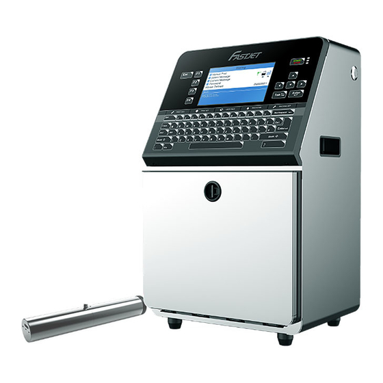
Summary of Contents for Fastjet F540 Series
- Page 1 Inkjet Printer F540/560/560Plus Series Operation Manual Apr 16 2020 Edited V1.1...
-
Page 2: Table Of Contents
Content 1. Safety Guidelines ------------------------------------- 1.1 safety warning -------------------------------------------------------------------- 1.2 Safety prevention ---------------------------------------------------------------- 1.3 Use ---------------------------------------------------------------------------------- 1.4 Handling ---------------------------------------------------------------------------- 1.5 Responsibility --------------------------------------------------------------------- 2. Introduction --------------------------------------------- 2.1 Appearance overview ----------------------------------------------------------- 2.2 Control Panel --------------------------------------------------------------------- 2.3 Printhead --------------------------------------------------------------------------- 2.4 Ink Core ---------------------------------------------------------------------------- 2.5 Main Screen ----------------------------------------------------------------------- 2.6 Menu Analysis... - Page 3 Content 3.2.2 Inkjet Observation ------------------------------------------------------ 3.2.3 Drops Observation ----------------------------------------------------- 3.3 Stop Jet --------------------------------------------------------------------------- 3.3.1 Stop Jet and Clean ----------------------------------------------------- 3.3.2 Stop and Clean (Power off during use of the printer) --------- 3.3.3 Stop and Clean (long-term stop of use) -------------------------- 3.4 Create Message ---------------------------------------------------------------- 3.4.1 Create a Sample Message...
- Page 4 Content 4.2 Failure and warning icons ---------------------------------------------------- 4.2.1 Failure icons ------------------------------------------------------------- 4.2.2 Warning icons ----------------------------------------------------------- 4.3 Troubleshooting ---------------------------------------------------------------- 4.4 Wash Nozzle -------------------------------------------------------------------- 4.5 Ink Jet Alignment --------------------------------------------------------------- 4.6 Drain( For F560Plus ) --------------------------------------------------------- 4.7 Clean Ink System -------------------------------------------------------------- 4.8 Sensor and Encoder Wiring Diagram ------------------------------------- 4.8.1 Sensor Diagram ---------------------------------------------------------...
-
Page 5: Safety Guidelines
1. Safety Guidelines 1.1 safety warning • Maintenance of this equipment must be performed by a maintenance professional. • When the printer is connected to the power supply and related circuits, a lethal voltage is generated. Non-professionals cannot open the circuit compartment, and cannot check and repair the circuit system. -
Page 6: Handling
• It is recommended to use the original consumables (including inks, solvents, cleaning agents, maintenance products, etc.) of the printer. You must obtain the Material Safety Data Sheet (MSDS) from the dealer and read and follow them carefully. Otherwise the consequences will be borne by the user. •... -
Page 7: Introduction
2. Introduction 2.1 Appearance overview Right View Front View Left View Introduction: 1. Power button 2. Upper:Electronics Compartment 、Control Panel 3. Lower:Ink Compartment 4. Connector Panel 5. Umbilical 2.2 Control Panel Page 3... -
Page 8: Printhead
2.3 Printhead Last Chance Filter Nozzle connector Nozzle Charge Electrode Phase Detector Deflection Plate Gutter Pipe 2.4 Ink Core * Exhaust Air Switch Condenser Cover Manifold Filter Gear Pump *Gutter Pump Drain Pipe Flushing * Exhaust Vent Plug Pump Ink Core(Front View) Ink Core(Back View) * Please remove the exhaust vent plug and turn on exhaust * It’s Gutter Pump for F560Plus... -
Page 9: Main Screen
2.5 Main Screen The main screen is the default screen after the printer powered on: Instructions: 1. The current status description area of the device; 2. A shortcut function keypad includes an user-defined function; 3. The name of the current message ; 4. -
Page 10: Menu Analysis
2.6 Menu Analysis 2.6.1 PRINT DATA 1. It is used to select and recall the stored messages , which is equivalent to the “F2 Select Message” on the main screen. 2. Used to create and edit saved messages. 3. Used to set the default message parameters. 4. -
Page 11: Print Set
2.6.3 PRINT SET 1. Used to enable or disable the printing function. if set to "Disable", the printer will disable the printing function and prompt "High voltage not activated" in the status bar. 2. It is used to select the printing quality, standard and high quality 01~15. The higher the high quality selection, the better the printing quality will be, but the slower the printing speed will be. -
Page 12: Ink System
2.6.4 INK SYSTEM 1. Flushing the nozzle blockage automatically. 2. After performing , open the printhead cover and use cleaning agent to clean the nozzle manually. Refer to 4.4 Nozzle Cleaning for details. 3. It is used to control the pump, valve and other parts separately. 4. -
Page 13: Machine Set
2.6.5 MACHINE SET 1. Used to disable the automatic shutdown caused by charge fault. 2. Used to disable the automatic shutdown caused by the gutter fault. 3. used to set the modulation value, manual/auto optional, auto mode only takes effect during startup. -
Page 14: F4 Password
2.6.6 F4 Password Only "Enter Password" menu is displayed before the password is entered. 1. Used to enter password; 2. Used to exit the password to level 0 (The lowest permission). 3. Used to set the password protection level of each function of the system. 4. -
Page 15: Photocell 1 Set
2.6.8 Photocell 1 Set 1. Select photocell 1 to be active by high or low level when triggering printing. 2. The way of the external photocell triggers printing, Gate or Trigger optional . 3. Within this time, the time interval between the trigger level and the trigger level can be obtained again (such as avoiding secondary sensing in the same product);... -
Page 16: Specifications
2.7 Specifications Electrical specifications Voltage 100V-240V AC Frequency 50Hz-60Hz Energy consumption 120(W) maximum value Weight Net weight 24KG Dimensions Cabinet 345L * 286W * 570H Printhead diameter 41mm Printhead length 260mm Nozzle size 70,60,50,40 μm Umbilical length 2700mm Environment specifications Operating temperature 5℃... -
Page 17: Printer Operation
3. Printer Operation 3.1 Commission(For F540/560/560Plus) Printer needs to be filled with ink and exhaust air before use. 1. Open the lower cabin door, pull out the ink system, and fill 500-750ml of ink into the mixer tank with a beaker in the order of A. -
Page 18: Start The Printer
3.2 Start The Printer 3.2.1 Start Jet 1. Connect the printer to an appropriate power source. 2. Open the printer head cover, check various components in the printhead, and check that various components are clean and dry. 3. Put on the printhead cover, press the power button at the right side of the printer, and wait for the screen to enter the main operation interface 4. -
Page 19: Inkjet Observation
3.2.2 Inkjet Observation Side View : Inkjet Charge Nozzle Electrode The inkjet is at the central position of the gutter pipe Front View: The inkjet is about 1/4 of the right side of the gutter pipe Nozzle Charge Electrode Page 15... -
Page 20: Drops Observation
3.2.3 Drops Observation The drops are generated after printer has started normally. It directly affects the printing effect and printing durability. Good drops roughly depend on the following three factors: Appropriate and stable pressure Correct ink viscosity Correct modulation value The observation method is as follows: 1. -
Page 21: Stop Jet
3.3 Stop Jet 3.3.1 Stop Jet and Clean 1. Press button, it lasts for about 4 minutes, the interface is as follows: 2. During cleaning after shutdown, remove the Printhead cover and observe if the printhead is dirty. If needed clean the printhead with the necessary cleaning agent. 3. -
Page 22: Create Message
2. Input file name TEST, then press enter key, as shown in the following figure: Press the CUSTOM button on this interface to pop up the Help window. 3. Press repeatedly. When the editing state is displayed as "16 High " then input “FastJet". Page 18... - Page 23 4. Press to select the “R” User Field (refer to 3.5.7 Logo), press the Enter key to insert, as shown below: In the editing interface, the function is “ Insert User Field ”. 5. After the content is entered, press to switch to the “Save Exit”...
-
Page 24: Create/Edit User Field
3.5 Create/Edit User Field 3.5.1 Time User Field Follow the steps below to create : 1. Enter the USER FIELD menu,select E) Edit/Create User Field - N) New User Field, as shown in the figure below: 2. Input a file name, switch “Attr” to “Time” then confirm , as shown in the figure below: 3. -
Page 25: Additional Remarks For Time User Field
3.5.2 Additional remarks for time user field Definition of Time User Field Code Definition Code Monday to Sunday Year Month Hour Minute Second Week Alpha Year Code Alpha Month Code Alpha Day Code Alpha Hour Code Alpha Minute Code 1. Actual printing date and time = system current time + number of days of Expiry term. -
Page 26: Barcode User Field
3.5.3 Barcode User Field The standards of barcode supported by the type include: QR Code (Figure 1), Data Matrix (Figure 2), Code39 (Figure 3), Code128 (Figure 4), EAN8 (Figure 5), EAN13 (Figure 6), EAN128 (Figure 7), UPC-A(Figure 8) Figure 1 Figure 2 Figure 3 Figure 4... -
Page 27: Additional Remarks For Barcode User Field
3.5.4 Additional remarks for Barcode User Field 1. The size (Height x Width) supported by Data Matrix include 10x10, 12x12, 14x14, 16x16, 18x18, 20x20, 22x22, 24x24, 26x26, 32x32, 8x18, 8x32, 12x26, 16x36, 16x48. 2. The size (height x width) supported by QR Code include 21x21, 25x25, 29x29, 33x33. -
Page 28: Counter User Field
3.5.5 Counter User Field 1. Enter the USER FIELD menu,select E) Edit/Create User Field - N) New User Field, as shown in the figure below: 2. Input a file name, switch “Attr” to “Text” then confirm , as shown in the figure below: The Items with mark available on F560/F560Plus only Instructions of each items refer to “... -
Page 29: Instructions For Items In The Counter
3.5.6 Instructions for Items in the Counter 1. Start value : Start value of the counter. 2. End value : End value of the counter 3. Reset value : Value to be reset when the function of "Reset Counter" of the Photocell 2 is used. -
Page 30: Logo User Field
3.5.7 Logo User Field The Logo User Field can create the customized logo of maximum 34 dots height ( F540 only support 25 dots ). 1. Enter the USER FIELD menu,select E) Edit/Create User Field - N) New User Field, as shown in the figure below: 2. - Page 31 4. After drawing, press the “ " key to set the logo size, as shown in the following figure: Press the CUSTOM button on this interface to pop up the Help window. 5. Complete logo size setting, press Enter to confirm the size, press to save and exit.
-
Page 32: Code User Field
3.5.8 Code User Field This function can integrate multiple User Fields ( Clock, counter and text ) in to generate a code. 1. Enter the USER FIELD menu,select E) Edit/Create User Field - N) New User Field, as shown in the figure below: Enter 2. -
Page 33: External Data User Field
3.5.9 External data User Field The function can receive the external data predefined by the user and print them in sequence. The preparation steps are as follows: 1. Enter the USER FIELD menu,select E) Edit/Create User Field - N) New User Field, as shown in the figure below: Enter 2. -
Page 34: Message Parameters
3.6 Message Parameters 3.6.1 Modify message parameters and contents In the main screen, press the key to enter the interface to modify current message contents and parameters, as shown in the figure; 1. "WYSIWYG" information editing area; 2. Parameter editing area,through to adjust parameters, width and delay parameters can be input directly. -
Page 35: Print Mode Setting
3.7 Print Mode Setting 3.7.1 Single Printing Mode The mode is commonly used for beer, beverage, food, daily necessities and other familiar industries . One trigger one printing. 1. Press PRINT SET button to enter the following setting interface: The GRAY options indicate that the setting is invalid for the "Single Print" mode. 2. -
Page 36: Continuous Printing Mode
3.7.2 Continuous Printing Mode The mode is commonly used for building materials, pipe, steel material and other industries. The common feature is continuous processing, messages automatic interval printing. 1. Press PRINT SET button to enter the following setting interface: The GRAY options indicate that the setting is invalid for the "Continuous Print" mode. 2. -
Page 37: Measure Mode
3.7.3 Measure mode The mode is commonly used in the wire cable, pipe and other industries requiring labelling of number of meters , the encoder must be used . 1. Press PRINT SET button to enter the following setting interface: The GRAY options indicate that the setting is invalid for the Measure Mode. -
Page 38: Traverse Printing Mode
3.7.4 Traverse Printing Mode The mode is commonly used in electronics, label printing, egg and other industries, and provides highly-efficient production mode for the array type printing. 1. Press PRINT SET button to enter the following setting interface: The GRAY options indicate that the setting is invalid for the Traverse Mode. 2. -
Page 39: Repeat Printing Mode
3.7.5 Repeat Printing Mode In this mode you can set the specific numbers of printing per trigger. 1. Press PRINT SET button to enter the following setting interface: The GRAY options indicate that the setting is invalid for the Repeat Mode. 2. -
Page 40: Maintenance
4. Maintenance 4.1 Diagnostic Screen In any interface, press i button to enter the diagnosis screen, and the interface is as follows: 1. Ink pressure and Ink Temperature. 2. Temp Cabinet: Actual upper cabinet temperature. Head : Heater temperature. 3. Phase angle and Phase Profile Value. 4. -
Page 41: Failure And Warning Icons
4.2 Failure and warning icons 4.2.1 Failure icons Icon Name Fault cause Solution Check the leaking position. Please Ink system leak consult the service engineer Mixing The solvent components in Tank the Mixer are vaporized after It is suggested to drain the old ink, Empty long-term storage of the and fill the new ink. -
Page 42: Warning Icons
4.2.2 Warning icons Icon Name Instructions for warning Jet printing The ink in the system is circulating and in good condition, operation the printer is ready for printing Jet printing The ink in the system is not circulating, the printer is in stop stopped state, and printing cannot be conducted Insufficient... -
Page 43: Troubleshooting
4.3 Troubleshooting • Turn on the power supply, there is no display on screen. Reason Solution No voltage of the power supply Check the power supply and related fuse • Poor jet printing character quality or incomplete character Reason Solution The printhead is too far from the Adjust the distance between the printhead product... -
Page 44: Wash Nozzle
4.4 Wash Nozzle When the nozzle is blocked, manual cleaning is required for the function. The operation procedures are as follows: 1. Press INK SYSTEM ,select and perform F) Wash Nozzle program. 2. After the program is started, manually clean the position shown in the following figure with cleaning agent. -
Page 45: Drain( For F560Plus )
4.6 Drain( For F560Plus ) Press INK SYSTEM button , perform the R) Drain program ,finish the drain operation according to the system prompt. The drain method of F540/F560 is different, more details please refer to the Official video or service manual 4.7 Clean Ink System Press INK SYSTEM button , perform the C) Clean Ink System program ,finish the drain operation according to the system prompt. -
Page 46: Sensor And Encoder Wiring Diagram
4.8 Sensor and Encoder Wiring Diagram 4.8.1 Sensor Diagram 4.8.2 Encoder Diagram Page 42... -
Page 47: Printer Stander
4.9 Printer Stander Page 43... - Page 48 Fastjet reserves the right to modify the technical characteristics of the product without prior notice. Manufacturer Name: Shanghai Fastjet Electronic Equipment Co., Ltd. A d d . : No.18 Building, Lane 699, Zhangwenmiao Road, Fengxian District, Shanghai Te l : 00 86 21-57484418 Fax: 00 86 21-57484498 http://www.fast-jet.com...
Need help?
Do you have a question about the F540 Series and is the answer not in the manual?
Questions and answers