
Related Manuals for Hy-Gain LJ-113


Summary of Contents for Hy-Gain LJ-113
- Page 1 LJ-113 3 element beam for 10 or 12 meters INSTRUCTION MANUAL CAUTION: Read All Instructions Before Operating Equipment 308 Industrial Park Road Starkville, MS 39759 USA Tel: 662-323-9538 Fax: 662-323-6551 COPYRIGHT 2012 Hy-gain. VERSION 1A...
-
Page 2: General Description
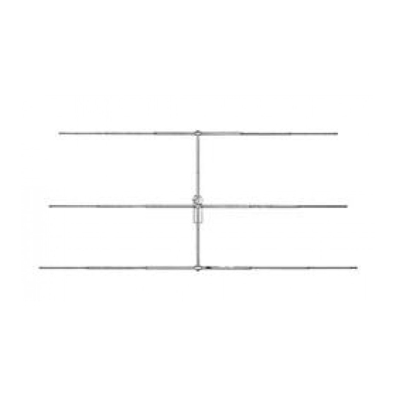
GENERAL DESCRIPTION This model is a 3-element beam tunable for maximum forward gain over the entire 10 or 12 meter band. Both the antenna and the beta match are adjustable for maximum performance. The elements are made of aircraft grade aluminum. The bracket will fit up to a 2 inch diameter mast. The electrical hardware is made from super strength stainless steel and all element tubing clamps are stainless steel. - Page 3 BOOM-TO-MAST ASSEMBLY Select the boom to mast bracket and clamp and install it on the boom as shown in figure 1. Use only the four outside holes, the elongated inside holes will be used for the U-bolts. The boom sections should meet in the middle of the bracket. 33-34 29-30 4 places...
- Page 4 Assemble both sides at the same time. Figure 4 R1 ASSEMBLY Select the R1 section of tubing and slip the un-slotted end into the bracket assembled on the boom. Tighten the bolts enough to hold the elements securely but do not tighten the anchor bolts at this time.
- Page 5 DRIVEN ELEMENT ASSEMBLY Select the large size set of element-to-boom brackets and loosely assemble these brackets on the boom in the approximate location according to the assembly chart. Select the driven element insulators and the DE1 sections of tubing. Slide the insulator on to the un-slotted end of the R1 (5) sections.
- Page 6 5/8 x 40-1/2 3/4 x 48 7/8 x 48 Figure 7 10 MTR 12 MTR PHONE PHONE 106-7/8 108-1/8 121-1/2 121-5/8 97-3/4 111-1/8 111-3/8 95-1/4 107-1/8 39-1/8 39-7/8 44-3/4 44-7/8 48-1/8 55-1/8 55-1/4 Beta All measurements are in inches and may vary with mounting location and height above ground.
-
Page 7: Final Assembly
FINAL ASSEMBLY A balun is not required for normal operation of this antenna. However there are three recommended feedpoint configurations. one which utilizes the Hy-gain Model BN-86 balun for increased performance and convenience. Final tuning may be required as the element lengths will vary based on mounting location and height above ground. - Page 8 RF Choke: 12 turns of RG-8/U with a six inch diameter. For optimum performance, use a Hy-gain BN-86 balun in Place of the choke. Figure 9 The first feedpoint configuration involves connection of the coaxial feedline directly to the driven element. The recommended feedline is RG-213/U. Other types of 50 ohm coaxial cable may be used if proper selection and careful assembly are utilized.
-
Page 9: Installation And Grounding
WEATHERPROOFING Weatherprooof the coax connectors using Coax-Seal or similar substance (not supplied). Securely tape the RF chokke and feedline to the antenna boom. Later when the antenna is mounted on the mast, the RF choke should be taped to the mast. Place a Caplug on the end of each boom. - Page 10 Bracket #2 element to boom 1-1/4 x 7/8------------------------ 172267 Beta match rod 20”-------------------------------------------------- 385142-1 Boom to mast bracket----------------------------------------------- 385144-1 Clamp, boom to mast bracket------------------------------------- 871988 PARTS PACK LJ-113 ----------------------------------------------- 163312 Clamp, 7/8 tubing---------------------------------------------------- 166084 Clamp, beta----------------------------------------------------------- 745-3106S #6 Hose clamp------------------------------------------------------- 656S-0375S-A...
- Page 11 Warrants to the original owner of this product, if manufactured by hy-gain and purchased from an authorized dealer or directly from hy-gain to be free from defects in material and workmanship for a period of 12 months for rotator products and 24 months for antenna products from date of purchase provided the following terms of this warranty are satisfied.
Need help?
Do you have a question about the LJ-113 and is the answer not in the manual?
Questions and answers