Table of Contents
Advertisement
Quick Links
Advertisement
Table of Contents

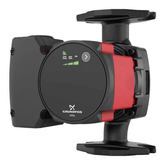
Summary of Contents for Grundfos UPSe
- Page 1 GRUNDFOS INSTRUCTIONS UPSe Installation and operating instructions...
- Page 3 UPSe English (US) Installation and operating instructions ............4...
-
Page 4: Table Of Contents
Operating panel, UPSe ..... . 13 consequential damages and some jurisdictions do not allow Light fields indication . -
Page 5: General Information
3.1 Product description Installation and operation must comply with local regulations and accepted codes of good practice. 2.1 Hazard statements The symbols and hazard statements below may appear in Grundfos installation and operating instructions, safety instructions and service instructions. DANGER Indicates a hazardous situation which, if not avoided, will result in death or serious personal injury. -
Page 6: Pumped Liquids
XXX°F / XXX°C Max ambient temp: non-explosive liquids without solid particles or fibers or mineral oils. XXX°F / XXX°C Grundfos Holding A/S If required, 50% of the volume solution of propylene glycol and Model: X DK -8850 Bjerringbro Made in XXXXXXX Denmark water can be used. -
Page 7: Approvals
3.4.2 Type key 4. Receiving the product Example: UPSe 15-58 FR 4.1 Inspecting the product Code Explanation Designation CAUTION UPSe Grundfos circulator Pump type Crushing of feet Small circulators Minor or moderate personal injury Maximum head [dm] ‐ Wear safety shoes when handling the product. -
Page 8: Installation Requirements
A damaged product must be repaired or replaced by • Slow down the flow to dissipate the heat in the zones Grundfos or a service workshop authorized by faster. This will also cause a larger temperature difference (delta Grundfos. T) between inlet and outlet of the boiler that keeps the boiler from short cycling. -
Page 9: Changing The Control Box Position
2. Install the pump with a horizontal motor shaft within ± 5°. 6.2 Changing the control box position CAUTION Hot surface Minor or moderate personal injury ‐ Position the pump so that persons cannot accidentally come into contact with hot surfaces. WARNING Pressurized system Minor or moderate personal injury... - Page 10 2. Turn the pump head to the desired position. You can turn the control box in steps of 90° if the flanges are in standard position (F) and in steps of 180° if the flanges are in flange rotated position (FR). Flanges in standard position (F) Flanges in flange rotated position (FR) 3.
-
Page 11: Electrical Connection
7. Electrical connection 7.1 Wiring the pump Note that the conduit connector and conduit are not supplied by WARNING Grundfos. Electric shock Follow the steps below to wire the pump: Death or serious personal injury 1. Remove the lid from the conduit box, and attach the conduit ‐... -
Page 12: Starting Up The Product
8. Starting up the product 8.2 Dry-running protection The dry-running protection protects the pump against dry running • Fill the system with liquid and vent it. during startup and normal operation. • Make sure the required minimum inlet pressure is available at the pump inlet. -
Page 13: Control Functions
9. Control functions 9.2 Light fields indication The LEDs indicate the control mode and setting. 9.1 Operating panel, UPSe Factory setting The pump is factory set to Zone pump, setting III. Active light fields Description Zone pump (constant curve) Zone valve (constant pressure) -
Page 14: Control Modes
The selection of the constant-curve setting depends on the characteristics of the heating system and the actual required flow/ Related information heat demand. 9.1 Operating panel, UPSe 10.1 Settings according to system type 9.3.3 Thermostatic radiator valve (TRV) (proportional pressure) Thermostatic radiator valve (TRV) (proportional pressure) mode... -
Page 15: Setting The Product
10. Setting the product 10.1 Settings according to system type • Press the button to select control mode and setting. System Recommended control mode The LEDs will indicate the control mode. See table below. A cycle is nine button presses. The factory setting is zone pump, setting III. -
Page 16: Service
Death or serious personal injury ‐ 1. Switch off the power supply. A damaged product must be repaired or replaced by Grundfos or a service workshop authorized by 2. Remove the lid from the conduit box. Grundfos. 3. Loosen the conduit. -
Page 17: Fault Finding
WARNING Electric shock Death or serious personal injury ‐ A damaged product must be repaired or replaced by Grundfos or a service workshop authorized by Grundfos. WARNING Hot surface Minor or moderate personal injury ‐ The pump housing may be hot due to the pumped liquid being scalding hot. -
Page 18: Undervoltage
13. Technical data Cause Remedy The pump is blocked by 1. Switch off the pump on the impurities. liquid side. Flow rate (Q) Max. 13.6 gpm (3.1 m Head (H) Max. 19 ft (5.8 m) 2. Remove the pump head. Supply voltage 1 ×... -
Page 19: Disposing Of The Product
This product or parts of it must be disposed of in an environmentally sound way. 1. Use the public or private waste collection service. 2. If this is not possible, contact the nearest Grundfos company or service workshop. See also end-of-life information at www.grundfos.com/product-... - Page 20 2941 Brighton Road Oakville, Ontario L6H 6C9 Tel.: +1-905 829 9533 Fax: +1-905 829 9512 Mexico Bombas GRUNDFOS de México S.A. de C.V. Boulevard TLC No. 15 Parque industrial Stiva Aeropuerto Apodaca, N.L. 66600 Tel.: +52-81-8144 4000 Fax: +52-81-8144 4010...
- Page 21 92795807 11.2022 ECM: 1341385 www.grundfos.com...


Need help?
Do you have a question about the UPSe and is the answer not in the manual?
Questions and answers