Grundfos Oxiperm Pro OCD-162-5 Series Installation And Operating Instructions Manual
Hide thumbs
Also See for Oxiperm Pro OCD-162-5 Series:

Related Manuals for Grundfos Oxiperm Pro OCD-162-5 Series


Summary of Contents for Grundfos Oxiperm Pro OCD-162-5 Series
- Page 1 GRUNDFOS ALLDOS INSTRUCTIONS ® Oxiperm OCD-162-5, OCD-162-10 Installation and operating instructions...
- Page 2 Declaration of Conformity We Grundfos Alldos declare under our sole responsibility that the products Oxiperm ® Pro, to which this declaration relates, are in conformity with the Council Directives on the approximation of the laws of the EC Member States relating to —...
-
Page 3: Table Of Contents
1. General safety instructions Page 1.1 Purpose of these operating instructions General safety instructions The Grundfos Alldos Oxiperm Pro disinfection system is a state- Purpose of these operating instructions of-the-art solution, which complies with recognised safety Symbols used in this document regulations. -
Page 4: Obligations Of The Operator
Affected skin and clothing must be washed are not in accordance with the intended use and are not immediately in water. permitted. The manufacturer, Grundfos Alldos, accepts no liability for any damage resulting from incorrect use. Warning The system comprises state-of-the-art components and has Risk of irritation to eyes, respiratory system and undergone safety-related testing. - Page 5 1.9.3 Procedure in case of an emergency The general safety regulations and regulations for the procedure in case of an emergency as specified in EN 12671: 2007 (D) apply. Actions in case of an emergency: • Ventilate the installation location immediately. •...
-
Page 6: Product Description
5. The dosing pump doses the corresponding quantity of the The Grundfos Alldos Oxiperm Pro disinfection system is used to solution from the reservoir tank into the main water line. produce and dose chlorine dioxide for the disinfection of drinking water, process water, cooling water and wastewater. -
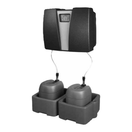
Page 7: Components Of The Standard Device
2.3 Components of the standard device blue Components of the Oxiperm Pro standard device Fig. 2 2.3.1 External parts 2.3.2 Internal components Pos. Components Pos. Components Water line for supplying dilution water and flushing Solenoid valve for supplying dilution water and water (via solenoid valve in the device) flushing water Bleeding point for dilution water with stopcock... -
Page 8: System Peripheral Devices And Accessories
7.5 % by volume) with suction lance and collecting pump to the injection unit (optional). tray • Grundfos Alldos DIT photometer (measures ClO Chemical container for HCl (diluted concentration of 9 concentration after dosing) (optional). % by volume) with suction lance and collecting tray •... -
Page 9: Hydraulic Connections
2.6 Power supply connections and electronic connections The Oxiperm Pro disinfection system is equipped with an electronic control system from Grundfos Alldos. See section 2.8 Control and display elements, fig. 6. The control system has connections for the following: •... -
Page 10: Control And Display Elements
2.8 Control and display elements During operation, press [Esc] to access the display level. PROCESS RUNNING ..5 °C 23 mg/ l pH 7 PROCESS RUNNING display level Fig. 7 The display and control panel Fig. 5 Fig. 7: 1-5, see table below: •... -
Page 11: Access Codes
Access is enabled for 60 minutes after entry. • Service code: This code is reserved for trained Grundfos Alldos service engineers. Access is enabled for 30 minutes after entry. The service code is necessary for commissioning. -
Page 12: User Menu Structure
2.10 User menu structure All software menus can be selected from the Users can view certain submenus in the display and can also MAIN MENU using the [Up] and [Down] buttons modify certain values. and accessed using [OK]. Note 2.10.1 Finding user menus Press [Esc] to return to the previous menu level. - Page 13 Dos. time monit. Off/on Cal. meas. value Chlorine dioxide Cal. result Slope µA, mg/l Cal. cycle On/off Cal. meas. value Grundfos, DIN/Nist, other Slope µA, mg/l Calibration Cal. result Asym. mV Cal. cycle On/off Cal. meas. value Redox Cal. result Asym.
-
Page 14: Transport And Packaging
Notes to table 2: Note 4*: • The ALARM settings are only available when MEASUREMENT has been enabled (using the service code). • The alarm relay is activated in case previously set alarm values for chlorine dioxide are exceeded or not reached, the maximum dosing time is exceeded, and in case of a fault. -
Page 15: Installation
4. Installation Operator’s checklist – preparing for installation Done Installation is described in detail in the separate service See section 6. Technical data instructions. 1. Read the Oxiperm Pro installation and operating This subsection can be used by operators to plan installation. instructions and the DMI 208 installation and operating instructions as well as the installation and 4.1 Planning installation... -
Page 16: Operation
5. Operation MAIN MENU PROCESS START ABORTION OPERATION CONTINUOUS ONCE PROCESS menu structure Fig. 8 5.1 Switching on the system Warning 1. Open the stopcock for the dilution water (1b). The Oxiperm Pro disinfection system uses 2. Switch on the main switch for the power supply. chemicals. -
Page 17: Starting Operation
5.3 Starting operation 5.4 Interrupting operation 5.3.1 Starting ClO production 5.4.1 Aborting ClO production 1. MAIN MENU > PROCESS > [OK]. 1. Access the MAIN MENU by pressing [OK] in the display level. 2. MAIN MENU > PROCESS > [OK]. PROCESS PROCESS START... -
Page 18: Continuing Operation After An Interruption
5.5 Continuing operation after an interruption 5.6 Flushing There are four ways in which operation can be interrupted: Warning • ABORT ClO PRODUCTION menu command (and after the Risk of poisoning from ClO gas. CONTROLLER OFF command) Never mix NaClO and HCl. - Page 19 5.6.2 Manually draining the reservoir tank 5.6.3 Starting flushing 1. Place the two 10-litre buckets filled with water to the right and 1. MAIN MENU > SERVICE > [OK]. left of the chemical containers. 2. PROCESS > [OK]. 2. Untwist the cover on the suction lance for the NaClO 3.
-
Page 20: Manually Ventilating The Dosing Pump
5.6.4 Working with the system after flushing 5.8 Modifying setup 1. Remove the hose from the drain cock, and place it in the Setup can be selected as follows: bucket. 1. MAIN MENU > SETUP > [OK]. 2. Pour the contents of the bucket down the drain. 3. - Page 21 8. DAYLIGHT SAV. T. > [OK]. 5.8.2 Changing the user code 9. BEGIN > [OK]. 1. SETUP > CODE FUNCTION > [OK]. BEGIN DAY. SAV. T. CODE FUNCTION TIME CHANGE CODE DATE DELETE CODE 10. TIME > [OK]. Change code: Use the [Up] or [Down] button to set the time daylight 2.
-
Page 22: Monitoring The Production And Dosing Process
5.9 Monitoring the production and dosing process The coloured fields in the service menu structure can only be accessed by service engineers. MAIN MENU SERVICE PROCESS PRODUCTION STATUS LIST OF EVENTS FLUSHING VENTILATION START ABORTION CYCLES CHEMICALS MAINTENANCE AGE OF ClO HCl/NaClO MEASUREMENT REDOX... - Page 23 5.9.1 Displaying current measured values for ClO Displaying the pH value water temperature and pH/redox 1. MAIN MENU > SERVICE > [OK]. 2. MEASUREMENT > [OK]. The measured values in this menu as well as the menus TEST CURRENT and TEST RELAY are MEASUREMENT only displayed if MEASUREMENT has been enabled (with the service code).
- Page 24 Displaying the redox value 5.9.2 Displaying the current dosing flow, controller type, setpoint and other control parameters 1. MAIN MENU > SERVICE > [OK]. 1. MAIN MENU > SERVICE > [OK]. 2. MEASUREMENT > [OK]. 2. ClO CONTROLLER > [OK]. MEASUREMENT Displaying the current proportional controller data If the system is controlled with a proportional controller:...
- Page 25 Displaying the current setpoint controller data Displaying the current combined controller data If the system is controlled with a setpoint controller: If the system is controlled with a combined controller: ClO2 CONTROLLER ClO2 CONTROLLER Y OUT: 75 % Y OUT: 75 % SETPT: 0.40 mg/l SETPT: 0.40 mg/l SETPOINT CONTRL...
- Page 26 5.9.3 Displaying the current input value for the water flow 5.9.7 Displaying the maintenance date meter 1. MAIN MENU > SERVICE > [OK]. 1. MAIN MENU > SERVICE > [OK]. 2. ClO PRODUCTION > [OK]. 2. WATER FLOW METER > [OK]. 3.
- Page 27 5.9.9 Indicating age of ClO in the reactor and in reservoir tank 1. MAIN MENU > SERVICE > [OK]. 2. ClO PRODUCTION > [OK]. PRODUCTION ClO2 CYCLES CHEMICALS MAINTENANCE AGE OF ClO 3. AGE OF ClO > [OK]. AGE OF ClO2 REACTOR 03:16 STOCK 00:00 The factory setting for both is 00:00 (minutes and seconds).
-
Page 28: Changing Alarm Settings
5.10 Changing alarm settings MAIN MENU ALARM ALARM VALUES DOS. TIME MONIT. ALARM VALUE 1 ALARM VALUE 2 HYSTERESIS ALARM DELAY UPWARD VIOLATION DOWNWARD VIOL. Fig. 15 User alarm settings To maintain the factory settings, proceed as follows: 5.10.1 Changing ClO alarm values Load the value or range to be checked using [OK], and exit the 1. - Page 29 To set the lower and upper switching points for the alarm, 5.10.2 Setting the hysteresis proceed as follows: 1. MAIN MENU > ALARM > [OK]. 2. ClO ALARM VALUES > [OK]. Changing alarm value 1 1. ALARM VALUE 1 > [OK]. ClO2 ALARM VALUES ALARM VALUE 1 ALARM VALUE 1...
-
Page 30: Changing Chemical Containers
5.11 Changing chemical containers Warning Risk of serious damage to equipment and personal injury due to confusing the chemical containers or suction lances. Observe the red and blue labels on chemical containers, suction lances and pumps. Warning Risk of burns from stray droplets when removing the lance from the chemical container. -
Page 31: Fault Finding
5.12 Fault finding Activated relays can be deactivated using the [Esc] key. An For trouble-free operation of the system, eliminate the cause of exception is the warning relay, which is activated using the signal the faults. "reservoir tank empty". This relay is only deactivated, if the fault is removed. - Page 32 Error message if applicable Cause Remedy system reaction 7. Timeout pump NaClO Level in the reactor increased too slowly Check correct assembly of the hose from – ClO production is aborted. during NaClO supply between contacts K2 pump to reactor. and K3.
- Page 33 Error message if applicable Cause Remedy system reaction 19. Water sensor fault: Stop the controller. – ClO production proceeds. a) Measuring cell float body above the water Reduce the flow with the measuring cell – Combined and setpoint controller sensor – flow too high. adjustment spindle.
- Page 34 Error message if applicable Cause Remedy system reaction 24. External error: An external device that may be connected to a – ClO production is aborted. "fault input" (terminal 53/54) indicates a fault. – Alarm relay activated. a) External device. Check the external device. –...
- Page 35 Error message if applicable Cause Remedy system reaction 31. ClO alarm value 1 or 2 exceeded Appears when the set upper switching point for Call Service. or not reached: the alarm is exceeded or not reached. – ClO production proceeds. –...
-
Page 36: Calibration
To calibrate the ClO measured value, a reference measurement I CELL 5.2 µA must be taken first, for example photometrically (with Grundfos 6. Use the [Up] or [Down] button to set the mg/l value to the Alldos DIT photometer and the usual ClO reagents). - Page 37 19. Screw the pH electrode back into the measuring cell. 8. GRUNDFOS > [OK]. The current pH value of the water in the main water line is updated in the display level.
- Page 38 14. Pour the contents of the bucket down the drain. Alternative method using the calibration lute Instead of unscrewing the electrode from the measuring cell, the Redox calibration has been completed. electrode can be left in the measuring cell, and the "calibration Alternative method using the calibration lute lute"...
-
Page 39: Emergency Stop
5.14 Emergency stop Aborting ClO production 1. MAIN MENU > PROCESS > [OK]. 2. ABORTION > [OK]. 3. ABORTION > [OK]. The chemical pumps are stopped. See section 5.4.1 Aborting production. Aborting the dosing process Switch off the controller in manual operation: 1. -
Page 40: Technical Data
6. Technical data Maximum back pressure for ClO dosing pump (10 g/h) 6.1 Identification DMI 50Hz: OCD-162-10-D/G 7 bar DMI 60Hz: OCD-162-10-D/H 5 bar DDI 50Hz: OCD-162-10-P/G(H) 10 bar DDI 60Hz: OCD-162-10-P/G(H) 10 bar Temperatures and humidity OCD-162 5D/G 162-005-10000 Permissible relative air humidity Maximum 80 % 5/N: 07/64064... - Page 41 Grundfos Alldos pumps Product number Pump 1 HCl Grundfos Voltage/ Grundfos Equipment For performance data, see the Alldos frequency DMI 6.0-8 installation and operating instructions With dosing for the DMI 6.0-8 pump 230 V, 95702474 162-005-10000 pump 50/60 Hz Connection on suction side PE hose 4/6 DMI 3.0-10...
- Page 42 Connections for the control system – inputs Current input 0(4)-20 mA Analog input for flow meter Load: 50 Ω Chlorine dioxide concentration Measuring cell (optional) Analog input Pt100 water temperature sensor in the measuring cell Contact water meter Contact input Maximum 50 pulses/second (compound-loop control) Maximum voltage: 13 V...
-
Page 43: Applicable Standards And Directives
Prior to installation, the operator must purchase the following DIN EN Applicable standards and directives accessories according to the product numbers in the Grundfos Alldos data booklet and the technical data. Pumps and pump units for liquids - The data booklet is available on www.Grundfosalldos.com. -
Page 44: Dimensional Sketch
9. Dimensional sketch 765 mm 765 mm 500 mm 500 mm 250 mm 250 mm 250 mm 250 mm 10,5 mm ∅10.5 mm 328 mm 328 mm NaClO NaClO2 Fig. 18 Oxiperm Pro with drill holes... -
Page 45: Photos
Oxiperm Pro disinfection system or its parts to a private disposal system. If there is none in your region, send the Oxiperm Pro to the nearest Grundfos Alldos company. Fig. 19 The Oxiperm Pro with components according to fig. 3 Pos. - Page 47 Telefax: +387 33 231795 GRUNDFOS Hellas A.E.B.E. GRUNDFOS Pumps NZ Ltd. Turkey 20th km. Athinon-Markopoulou Av. 17 Beatrice Tinsley Crescent GRUNDFOS POMPA San. ve Tic. Ltd. Sti. Brazil P.O. Box 71 North Harbour Industrial Estate Mark GRUNDFOS Ltda. Gebze Organize Sanayi Bölgesi...
- Page 48 Being responsible is our foundation Thinking ahead makes it possible Innovation is the essence 15.710168 V4.0 Repl. 15.710168 V3.0 96772142 0309 Repl. 96772142 0208 www.grundfosalldos.com...
Need help?
Do you have a question about the Oxiperm Pro OCD-162-5 Series and is the answer not in the manual?
Questions and answers