Advertisement
- 1 Further information
- 2 Wiring of power supply and motor
- 3 Wiring of the main circuit
- 4 Wiring
- 5 Wiring method
- 6 Wiring of the control circuit
- 7 Input signals
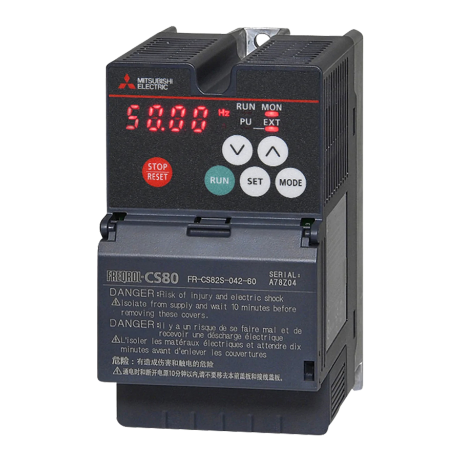
- 8 Components of the operation panel
- 9 Basic operation
- 10 Changing the parameter setting value
- 11 Basic parameters
- 12 Overview of the error messages
- 13 Documents / Resources
Further information

There is a risk to the life and health of the user if appropriate precautionary measures are not taken. The precautions can be found in the instruction manual of the frequency inverter FR-CS80.
If you have any questions about the installation, programming and operation of the frequency inverter, please do not hesitate to contact your sales office or one of your sales partners. You can reach our technical support at the following number: +49 (0) 2102 103 7914
Wiring of power supply and motor
| Terminal | Power supply | Motor connection | Earth | DC link choke, brake resistor, brake unit |
| 230 V, 1~ |  |  |  |  |
| 400 V, 3~ |  | |  |  |
Wiring of the main circuit
Use insulated blade terminals to connect the power supply and the motor.
| Terminal | Description |
| R/L1, S/L2, T/L3 1 | Power supply connection |
| U, V, W | Motor connection |
| P/+ b, PR | Connection for external brake resistor |
| P/+ b, N/- | Connection for external brake unit |
| P/+2, P1 | Connection for DC link choke |
 | PE |
1 L1 and N for single phase power supply.
2 For single-phase frequency inverters, this terminal is marked with "+".
Wiring

 Main circuit terminal
 Control circuit terminal
Wiring method
Power supply connection
- Strip off the sheath for the below length. If the length of the sheath peeled is too long, a short circuit may occur with neighboring wires. If the length is too short, wires might come off.
Wire the stripped cable after twisting it to prevent it from becoming loose. In addition, do not solder it

- Crimp the blade terminal.
Insert wires to a blade terminal, and check that the wires come out for about 0 to 0.5 mm from a sleeve. Check the condition of the blade terminal after crimping. Do not use a blade terminal of which the crimping is inappropriate, or the face is damaged. Blade terminals commercially available (as of February 2017)

 Blade terminals commercially available (as of February 2017)
Wiring of the control circuit
Recommended cable gauge: 0.3 to 0.75 mm2

Input signals
Use a wire end ferrule and a cable for the connection to the terminals where the end is striped appropriately. Single-core cables can be connected directly to the terminals after removing the insulation.
| Terminal | Description | ||
| STF | Forward rotation start signal | ||
| STR | Reverse rotation start signal | ||
| RH, RM, RL | Multi-speed selection | ||
| SD | Common terminal for the contact input terminal (sink logic). Common terminal (0 V) for the 24 V DC power supply (terminal PC). | ||
| PC | 24 V DC output and common terminal for control circuit inputs in source logic | ||
| Terminal | Type | Description | |
| 10 | Frequency setting power supply | Used as the power supply for an external device such as a frequency setting potentiometer or digital panel meter. | |
| 2 | Frequency setting (voltage) | Inputting 0 to 5 V DC (or 0 to 10 V DC) provides the maximum output frequency at 5 V (or 10 V) and makes input and output proportional. | |
| 4 | Frequency setting (current) | Inputting 4 to 20 mA DC Current input Voltage (or 0 to 5 V, 0 to 10 V) (initial status) input provides the maximum output frequency at 20 mA and makes input and output proportional. This input signal is valid only when the AU signal is ON (terminal 2 input is invalid). | |
| 5 | Frequency setting and analog outputs common | Terminal 5 represents the reference point (0 V) for all analog setpoint values and for the analog output signal AM (voltage). The terminal is isolated from the reference potential of the digital circuit (SD). | |
| 10 | PTC input (PTC sensor) | Terminals 10 and 2 serve as an input for a PTC sensor (thermal motor protection). | |
| 2 | |||
| A, B, C | Relay output | A changeover contact output that indicates that an inverter's protective function has been activated and the outputs are stopped. | |
| RS-485 | PU interface | The PU connector supports the RS-485 communication. | |
Components of the operation panel

| Appearance | Name | Description |
 | STOP/ RESET key | Stops the operation commands. Used to reset the inverter when the protective function is activated. |
 | UP/DOWN key | Used to change the setting of frequency or parameter, etc. The following operations are also enabled:
|
 | MODE key | Switches the monitor screen (item) in the monitor mode. Every key on the operation panel becomes inoperable (locks) by holding this key for 2 seconds. The key lock function is disabled when Pr.161 = "0 (initial value)". Holding this key for one second displays the initial screen. (During normal inverter operation it will appear as the first screen in the monitor mode; during abnormal operation it will appear as the first screen in the fault history mode. Reverts to the previous screen if pressed during frequency setting when the easy setting function is enabled. |
 | ||
 | SET key | Confirms each selection. Pressing this key in a mode other than the parameter setting mode will display parameter settings. |
 | RUN key | Used to give the start command to the inverter. The rotation direction depends on the Pr.40 setting. |
Basic operation

- The monitor items can be changed.
- In each fault record display, "0" is displayed instead of the fault indication when no fault record exists.
- "P. 0" will appear if the MODE key is pressed during parameter setting.
Changing the parameter setting value
Change the setting of Pr.1 Maximum frequency.
Operating procedure
- Turning ON the power of the inverter
The operation panel is in the monitor mode. - Selecting the parameter setting mode
Press![]() to choose the parameter setting mode.
to choose the parameter setting mode. - Selecting the parameter
Press![]() or
or ![]() to show
to show ![]()
![]() (Pr.1). Press
(Pr.1). Press ![]() to read the present set value.
to read the present set value.
![]() (initial value) appears.
(initial value) appears. - Changing the setting value
Press![]() or
or ![]() change the set value to
change the set value to ![]() . Press
. Press ![]() to enter the setting
to enter the setting ![]() and
and ![]()
![]() are displayed alternately.
are displayed alternately.
 to choose the parameter setting mode.
 or
or  to show
 (Pr.1). Press
  (initial value) appears.
 . Press
 - Press
![]() or
or ![]() to read another parameter.
to read another parameter. - Press
![]() to show the setting again.
to show the setting again. - Press
![]() twice to show the next parameter.
twice to show the next parameter. - Press
![]() for one second to return the display to the first screen in the monitor mode (the monitor item initially set in the first screen is the frequency).
for one second to return the display to the first screen in the monitor mode (the monitor item initially set in the first screen is the frequency).
 for one second to return the display to the first screen in the monitor mode (the monitor item initially set in the first screen is the frequency).
NOTE
- If a parameter write condition is not satisfied, a parameter write error appears on the LCD display. N
- When Pr.77 Parameter write selection = "2 (initial value)", the parameter setting change is available only while the inverter is stopped and under the PU operation mode. To enable the parameter setting change while the inverter is running or under the operation mode other than PU operation mode, change the Pr.77 setting.
| Error indication | Description |
 | Parameter write error |
 | Write error during operation |
 | Calibration error |
 | Mode designation error |
Basic parameters
| Pr. | Description | Minimum setting increment | Initial value | Setting range | |
| 0 | Torque boost | 0.1% | 6/4/3 %1 | 0–30% | |
| 1 | Maximum frequency | 0.01 Hz | 120 Hz | 0–120 Hz | |
| 2 | Minimum frequency | 0.01 Hz | 0 Hz | ||
| 3 | Base frequency | 0.01 Hz | 50 Hz | 0–400 Hz | |
| 4 | Multi-speed setting | RH | 0.01 Hz | 50 Hz | 0–400 Hz |
| 5 | RM | 30 Hz | |||
| 6 | RL | 10 Hz | |||
| 7 | Acceleration time | 0.1 | 5/10 s1 | 0–3600 s | |
| 8 | Deceleration time | ||||
| 9 | Electronic thermal O/L relay | 0.01A | Inverter rated current | 0–500 A | |
| 79 | Operation mode selection | 1 | 0 | 0/1/2/3/4/6/7 | |
| 125 | Frequency setting gain frequency | Terminal 2 | 0.01 Hz | 50 Hz | 0–400 Hz |
| 126 | Terminal 4 | ||||
1The factory setting depends on the performance class of the frequency inverter.
Overview of the error messages
If a protective function has been activated, eliminate the cause of the error and then reset the frequency inverter. It is imperative that you follow the procedure in the instruction manual for the FR-CS80 frequency inverter. You can reset the frequency inverter by pressing the STOP/RESET button on the operation panel (only after a serious error), by switching the power supply off and on again, or by switching the RES signal.
| Operation panel indication | Name | ||
| Error messages |  | HOLD | Operation panel lock |
 | LOCD | Password locked | |
 | ER1–ER4 | Parameter write error | |
 | Err. | Error | |
| Warning messages |  | OL | Stall prevention (overcurrent) |
 | oL | Stall prevention (overvoltage) | |
 | TH | Electronic thermal O/L relay prealarm | |
 | PS | PU stop | |
 | UV | Undervoltage | |
| Slight error |  | iH | Inrush current limit resistor overheat |
 | FN | Faulty fan | |
| Serious error |  | E.OC1 | Overcurrent trip during acceleration |
 | E.OC2 | Overcurrent trip during constant speed | |
 | E.OC3 | Overcurrent trip during deceleration or stop | |
 | E.OV1 | Regenerative overvoltage trip during acceleration | |
 | E.OV2 | Regenerative overvoltage trip during constant speed | |
 | E.OV3 | Regenerative overvoltage trip during deceleration or stop | |
 | E.THT | Inverter overload trip (electronic thermal O/L | |
 | E.THM | Motor overload trip (electronic thermal O/L | |
 | E.FIN | Heatsink overheat | |
 | E.JLF | Input phase loss | |
 | E.OLT | Stall prevention stop | |
 | E.GF | Output side earth (ground)fault overcurrent | |
 | E.LF | Output phase loss | |
 | E.OHT | External thermal relay operation | |
 | E.PE | Parameter storage device fault | |
 | E.PUE | PU disconnection | |
 | E.RET | Retry count excess | |
 | E.5 | CPU fault | |
 | E.CPU | ||
 | E.CDO | Abnormal output current detection | |
 | E.IOH | Inrush current limit circuit fault | |
 | E.E 10 | Inverter output fault | |
Mitsubishi Electric Europe B.V. /// FA - European Business Group /// Germany ///
Tel.: +49(0)2102-4862048 /// Fax: +49(0)2102-4861120 /// https://eu3a.mitsubishielectric.com

Documents / Resources
References
Download manual
Here you can download full pdf version of manual, it may contain additional safety instructions, warranty information, FCC rules, etc.
Download Mitsubishi Electric FR-CS82S, FR-CS84 - Frequency Inverter Quick Start Guide
Advertisement


Need help?
Do you have a question about the FR-CS82S and is the answer not in the manual?
Questions and answers