ambiq micro Apollo4 Plus EVB Display Kit Quick Start Manual
Hide thumbs
Also See for Apollo4 Plus EVB Display Kit:
- Quick start manual (22 pages) ,
- Quick start manual (21 pages) ,
- Quick start manual (21 pages)

Related Manuals for ambiq micro Apollo4 Plus EVB Display Kit


Summary of Contents for ambiq micro Apollo4 Plus EVB Display Kit
- Page 1 QUICK START GUIDE Apollo4 Plus EVB Display Kit (Shield Board Revision 1) Ultra-low Power Apollo SoC Family Doc. ID: QS-A4PDK-1p0 Doc. Revision: 1.0, September 2022...
- Page 2 BODY, OR OTHER APPLICATIONS INTENDED TO SUPPORT OR SUSTAIN LIFE, OR FOR ANY OTHER APPLICA- TION IN WHICH THE FAILURE OF THE AMBIQ MICRO PRODUCT COULD CREATE A SITUATION WHERE PER- SONAL INJURY OR DEATH MAY OCCUR. SHOULD BUYER PURCHASE OR USE AMBIQ MICRO PRODUCTS...
-
Page 3: Table Of Contents
5. Overview of the Apollo4 Display Kit ..............10 6. Software Development Tools ................14 7. Graphics Development Tools ................15 8. Hardware Configuration Options ................. 16 9. Ordering Information ................... 18 QS-A4PDK-1p0 Page 3 2022 Ambiq Micro, Inc. All rights reserved. - Page 4 Apollo4 Plus Display Kit Block Diagram - MSPI0/MSPI1 Octal to PSRAM/Flash..11 Apollo4 Plus Display Shield Parts Locations ............12 PSU page of the Display Shield schematic............... 16 GPIO79 Pin Connection Options ................17 QS-A4PDK-1p0 Page 4 2022 Ambiq Micro, Inc. All rights reserved.
- Page 5 Apollo4 Plus Display Kit Quick Start Guide List of Tables Document Revision History..................7 EVB / Shield Ordering Information................18 MCU Ordering Information..................18 QS-A4PDK-1p0 Page 5 2022 Ambiq Micro, Inc. All rights reserved.
-
Page 6: Introduction
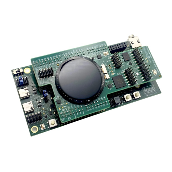
The Apollo4 Plus Display Kit is also intended to provide an introduction to the GUI Builder. Figure 1. Apollo4 Plus Display Kit QS-A4PDK-1p0 Page 6 2022 Ambiq Micro, Inc. All rights reserved. -
Page 7: Document Revision History
Apollo4 Plus Display Kit Quick Start Guide Document Revision History Table 1: Document Revision History Rev # Date Description September 2022 Document initial public release QS-A4PDK-1p0 Page 7 2022 Ambiq Micro, Inc. All rights reserved. -
Page 8: Reference Documents And Software
The following items may be useful in understanding and using the EVB. ▪ EVB Schematic ▪ Apollo4 Plus SoC Datasheet ▪ Apollo4 Family Programmer’s Guide ▪ Apollo4 Plus Errata List ▪ AmbiqSuite SDK QS-A4PDK-1p0 Page 8 2022 Ambiq Micro, Inc. All rights reserved. -
Page 9: Quick Start
The AmbiqSuite SDK provides many example programs that may be run on the Display Kit. To run these examples, download the SDK via the link provided above and select any of the pre-built examples in the SDK at /boards/apollo4p_evb_disp_shield_rev2/examples. QS-A4PDK-1p0 Page 9 2022 Ambiq Micro, Inc. All rights reserved. -
Page 10: Overview Of The Apollo4 Display Kit
Plus Audio Jack Display Shield Debug In/Out THGBMNG5D1LBAIT SDIF e-MMC Connectors MCU USB Connector ADXL362 Accel Figure 2. Apollo4 Plus Display Kit Block Diagram - MSPI0 Hex to PSRAM Only QS-A4PDK-1p0 Page 10 2022 Ambiq Micro, Inc. All rights reserved. - Page 11 Plus Plus Audio Jack Display Shield Debug In/Out THGBMNG5D1LBAIT SDIF e-MMC Connectors MCU USB Connector ADXL362 Accel Figure 3. Apollo4 Plus Display Kit Block Diagram - MSPI0/MSPI1 Octal to PSRAM/Flash QS-A4PDK-1p0 Page 11 2022 Ambiq Micro, Inc. All rights reserved.
- Page 12 For a full overview of the Apollo4 Plus EVB's offerings, please refer to the AMAP4PEVB Quick Start Guide, which includes information about the debug interface. Caution: The EVB has components loaded on the back of the board. Care should be taken to not damage these components. QS-A4PDK-1p0 Page 12 2022 Ambiq Micro, Inc. All rights reserved.
- Page 13 Apollo4 Plus Display Kit Quick Start Guide Secure Boot on the Apollo4 SoC Apollo4 Plus SoC parts from the Ambiq Micro factory are preprogrammed with a Secure Bootloader and an uninitialized Customer Info Space, referred to as INFO0. Initial provisioning of the part would include programming a valid INFO0 and programming the main firmware image in the flash.
-
Page 14: Software Development Tools
Regardless of preferred IDE, please install the Segger J-Link software. All of the above development environments support J-Link, but you must have the latest J-Link software installed. Most alternate development environments also are supported by J-Link. QS-A4PDK-1p0 Page 14 2022 Ambiq Micro, Inc. All rights reserved. -
Page 15: Graphics Development Tools
Transitions and Animations ▪ Alpha blending ▪ Programmable size, offset and format per layer ▪ Programmable stride/pitch enabling panning and clipping Other Features ▪ Transparency ▪ Color keying ▪ Multi-function image processing QS-A4PDK-1p0 Page 15 2022 Ambiq Micro, Inc. All rights reserved. -
Page 16: Hardware Configuration Options
AMAP4PEVB. ▪ VDD_MCU of AMAP4PEVB – Open SB4, Short SB5, connect jumper between VDD_EXT and VDD_MCU on J3 of AMAP4PEVB. Figure 5. PSU page of the Display Shield schematic QS-A4PDK-1p0 Page 16 2022 Ambiq Micro, Inc. All rights reserved. - Page 17 (AP4_DISP_SDI) hardware connections for the GPIO79 pin. By default, the hardware is configured to connect to the e-MMC device. Figure 6. GPIO79 Pin Connection Options Other Solder-bridge Options For other solder-bridge options, please consult the Apollo4 Plus EVB Quick Start Guide. QS-A4PDK-1p0 Page 17 2022 Ambiq Micro, Inc. All rights reserved.
-
Page 18: Ordering Information
2 MB 2.75 MB Tape and Reel –20 to 60°C 146-pin BGA a. The silicon revision is identified by the first letter in the bottom row of the package's top marking. QS-A4PDK-1p0 Page 18 2022 Ambiq Micro, Inc. All rights reserved. - Page 19 2022 Ambiq Micro, Inc. All rights reserved. Ambiq Micro, Inc. 6500 River Place Boulevard, Building 7, Suite 200, Austin, TX 78730-1156 www.ambiq.com/ sales@ambiqmicro.com https://support.ambiqmicro.com +1 (512) 879-2850 QS-A4PDK-1p0 Version 1.0 September 2022...
Need help?
Do you have a question about the Apollo4 Plus EVB Display Kit and is the answer not in the manual?
Questions and answers