
Related Manuals for ambiq micro Apollo2 Blue


Summary of Contents for ambiq micro Apollo2 Blue
- Page 1 Apollo2 Blue EVB Quick Start Guide Apollo2 Blue EVB Board Revision 0.3 Quick Start Guide Doc. ID: QS-A2Br0_3-1p00 Document Revision 1.0 Sep 2017 QS-A2Br0_3-1p00 Page 1 2017 Ambiq Micro, Inc. All rights reserved.
- Page 2 ..............................Document Revision History ........................Overview of the Apollo2 Blue EVB ...................... Debug Interface ............................Software Development Tools for the Apollo2 Blue EVB ............Power Supply Options and Measuring Current ................QS-A2Br0_3-1p00 Page 2 2017 Ambiq Micro, Inc. All rights reserved.
-
Page 3: Table Of Contents
Apollo2 Blue EVB Quick Start Guide List of Figures Apollo2 Blue EVB, Revision 0.3 ......................BLE PHY testing through RF switch/connector (J1) on Apollo2 Blue EVB ..... Apollo2 Blue EVB using On-board J-Link Debugger ..............Apollo2 Blue EVB’s Cortex DEBUG IN Header (J3) .............. - Page 4 Apollo2 Blue EVB Quick Start Guide List of Tables Document Revision History ........................Jumper Configuration for Power Selections ................. QS-A2Br0_3-1p00 Page 4 2017 Ambiq Micro, Inc. All rights reserved.
-
Page 5: Document Revision History
Apollo2 Blue EVB Quick Start Guide Introduction This document provides guidance in setting up the Apollo2 Blue Evaluation Board (EVB), revision 0.3, to get started executing code examples, measuring power consumption in various configurations, and beginning software development. Document Revision History... -
Page 6: Overview Of The Apollo2 Blue Evb
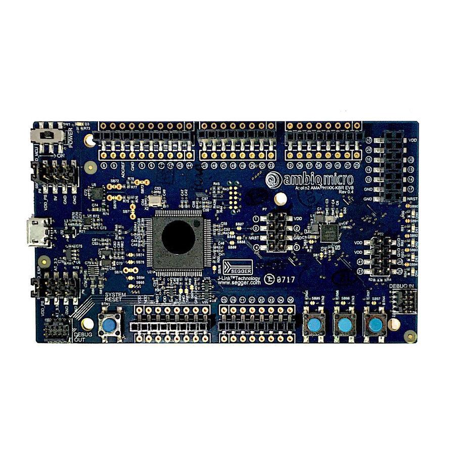
▪ Five 8-12 pin Arduino-style headers for pin/power access to shield board(s) ▪ Multiple test points for power measurements ▪ CE Mark and RoHS compliant Figure 2 shows the Apollo2 Blue EVB under RF testing via the RF switch/connector. QS-A2Br0_3-1p00 Page 6 2017 Ambiq Micro, Inc. -
Page 7: Ble Phy Testing Through Rf Switch/Connector (J1) On Apollo2 Blue Evb
Apollo2 Blue EVB Quick Start Guide Figure 2. BLE PHY testing through RF switch/connector (J1) on Apollo2 Blue EVB QS-A2Br0_3-1p00 Page 7 2017 Ambiq Micro, Inc. All rights reserved. -
Page 8: Debug Interface
Apollo2 Blue EVB Quick Start Guide Debug Interface Figure 3 shows the Apollo2 Blue EVB set up for standard debug using the on-board J-Link debugger and on-board power supply configured for 3.3V. Segger J-Link Adapter Figure 3. Apollo2 Blue EVB using On-board J-Link Debugger The debug interface is supported by standard J-Link drivers from Segger. -
Page 9: Apollo2 Blue Evb's Cortex Debug In Header (J3)
OUT” header (J4) on the EVB to the debug header on the target board. The EVB will automatically detect when the “DEBUG OUT” header is connected to another target board and reconfigure the integrated J- Link to connect to this external board rather than the on-board Apollo2 Blue. QS-A2Br0_3-1p00 Page 9 2017 Ambiq Micro, Inc. - Page 10 Apollo2 Blue EVB Quick Start Guide Note: A voltage on pin 1 of the J4 header is required for the above mentioned automatic switch to occur. Also, if the target VDD doesn't match the on-board voltage (either 3.3V or 1.9V), and to avoid possible voltage level conflicts on the debug I/O port, VDDIO of the J-Link processor may need to be changed to the target voltage by cutting SB9 and shorting SB10.
-
Page 11: Software Development Tools For The Apollo2 Blue Evb
Software Development Tools for the Apollo2 Blue EVB The standard Segger J-Link debug interface is used on the Apollo2 Blue EVB. Please install the latest Beta Segger J-Link software, and configure your preferred development IDE (Keil, IAR, or Eclipse) to use J- Link debug interface. -
Page 12: Voltage Selection On Header P19
Apollo2 Blue EVB Quick Start Guide Power Supply Options and Measuring Current There are three power supply options for the Apollo2 Blue EVB: ▪ Operate at 3.3V as provided by the on-board power supply ▪ Operate at 1.9V as provided by the on-board power supply ▪... -
Page 13: Header P19 Configured For 3.3V Operation - No Current Measurement
Apollo2 Blue EVB Quick Start Guide a. Note that the Apollo2 Blue EVB supports only Step Down operation for the BLE, and therefore does not sup-port the full voltage range of the device. As an example for setting the jumpers on P19, Figure 7 shows the EVB configured for 3.3V operation with jumper across VDD_PS and VDD_MCU for no current measurement. - Page 14 Apollo2 Blue EVB Quick Start Guide FCC Warring Statement FEDERAL COMMUNICATIONS COMMISSION INTERFERENCE STATEMENT This equipment has been tested and found to comply with the limits for a Class B digital device, pursuant to Part 15 of the FCC Rules. These limits are designed to provide reasonable protection against harmful interference in a residential installation.
- Page 15 HOW-EVER, CONTAIN TECHNICAL INACCURACIES, TYPOGRAPHICAL ERRORS OR OTHER MISTAKES. AMBIQ MICRO MAY MAKE CORRECTIONS OR OTHER CHANGES TO THIS CONTENT AT ANY TIME. AMBIQ MICRO AND ITS SUPPLIERS RESERVE THE RIGHT TO MAKE CORRECTIONS, MODIFICATIONS, ENHANCEMENTS, IMPROVEMENTS AND OTHER CHANGES TO ITS PRODUCTS, PROGRAMS AND SERVICES AT ANY TIME OR TO DISCONTINUE ANY PRODUCTS, PROGRAMS, OR SERVICES WITHOUT NOTICE.
Need help?
Do you have a question about the Apollo2 Blue and is the answer not in the manual?
Questions and answers