Table of Contents
Advertisement
Quick Links
Advertisement
Table of Contents

Related Manuals for Becom Argos3D-Pulse


Summary of Contents for Becom Argos3D-Pulse
- Page 1 Argos3D-Pulse Quick Start Guide Version 2...
- Page 2 Quick Start Guide - Argos3D-Pulse Last change: 1 October 2021/Version 2 BECOM Systems GmbH Gutheil-Schoder-Gasse 17 1230 Wien AUSTRIA office.systems@becom-group.com systems.becom-group.com Argos3D-Pulse – Quick Start Guide Document No.: 900-308 / A Publication date: October 1, 2021 Subject to change without notice. Errors excepted.
-
Page 3: Table Of Contents
1.3.3 Connecting the Ethernet Cable ..............................7 Evaluation Software ......................................8 Prepare your Network Interface Card (NIC) ..........................8 Start using your Argos3D-Pulse with ‘BltTofSuite’ .......................8 System Requirements & Support ................................9 Support ..........................................9 Document Revision History ................................... 10 List of Figures and Tables ....................................11 ©... - Page 4 BECOM Systems specifically disclaims any implied warranty of merchantability or fitness for a particular purpose. BECOM Systems takes no liability for any damages and errors causing of the usage of this board. The user of this board is responsible by himself for the functionality of his application.
-
Page 5: Unboxing
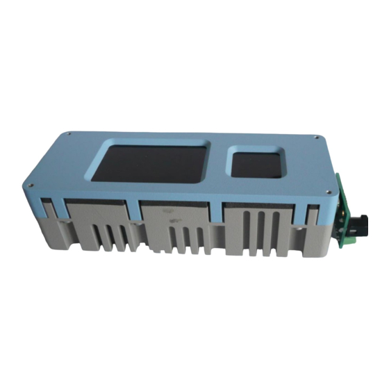
1.2 Connecting your Argos3D-Pulse 1.3 Connector Overview The Argos3D-Pulse uses one common connector for power and interfaces. For test purposes the KIT contains a breakout-board to have individual access to the interfaces of the Argos3D-Pulse. The break-outboard has three main interfaces: Power Connector b. -
Page 6: Connecting The Break-Out Board
1.3.2 Connecting the power supply To ensure, that your Argos3D-Pulse works correctly, connect the ‘Argos3D’ to a 12-30V DC power supply using connector (a) and wait for approximately 20 seconds until the camera boots up. Pin assignment on the power connector (a): Pin #1: +12V to +30V, Pin#2: GND Note The power supply connector is protected against wrong polarity but the ‘Argos3D’... -
Page 7: Connecting The Ethernet Cable
Quick Start Guide - Argos3D-Pulse Last change: 1 October 2021/Version 2 1.3.3 Connecting the Ethernet Cable Plug in the Ethernet cable (b) and connect your Argos3D-Pulse to your PC. Figure 1-3: Argos3D-Pulse connected to power and Ethernet © BECOM Systems 2021 7 | 11... -
Page 8: Evaluation Software
Download”. Please select the Argos3D-Pulse product link and download the Blt Tof Suite. 2.1 Prepare your Network Interface Card (NIC) Once you have connected your Argos3D-Pulse to a Network Interface Card (NIC) of your PC give this NIC the IP- Address 192.168.0.1 with a subnet mask of 255.255.255.0. -
Page 9: System Requirements & Support
Quick Start Guide - Argos3D-Pulse Last change: 1 October 2021/Version 2 3 System Requirements & Support An Argos3D-Pulse enabled application is required in order to use this ‘Argos3D’ device. Connect to a system with: • Operating System: Microsoft Windows 7/8/10 32 bit (x68) or 64 bit (x64) processor •... -
Page 10: Document Revision History
Quick Start Guide - Argos3D-Pulse Last change: 1 October 2021/Version 2 4 Document Revision History Version Date Document Revision 2021 08 02 First draft 2021 10 01 Review, minor changes and release Table 4-1: Revision history © BECOM Systems 2021... -
Page 11: A List Of Figures And Tables
Last change: 1 October 2021/Version 2 A List of Figures and Tables Figures Figure 1-1: Argos3D-Pulse break-out board front and rear view ......................... 5 Figure 1-2: Argos3D-Pulse common connector ................................6 Figure 1-3: Argos3D-Pulse connected to power and Ethernet ..........................7 Tables Table 4-1: Revision history..........................................
Need help?
Do you have a question about the Argos3D-Pulse and is the answer not in the manual?
Questions and answers