Table of Contents
Advertisement
Quick Links
Advertisement
Chapters
Table of Contents

Related Manuals for Becom TOREO-P650


Summary of Contents for Becom TOREO-P650
- Page 1 TOREO-P650 Hardware User Manual Version 1...
- Page 2 Hardware User Manual - TOREO-P650 Last change: 6 September 2021/Version 1 BECOM Systems GmbH Gutheil-Schoder-Gasse 17 1230 Wien AUSTRIA office.systems@becom-group.com http://systems.becom-group.com TOREO-P650 – Hardware User Manual Document No.: 900-308 / A Publication date: September 6, 2021 Subject to change without notice. Errors excepted.
-
Page 3: Table Of Contents
Hardware User Manual - TOREO-P650 Last change: 6 September 2021/Version 1 Table of Contents General Information ......................................6 Symbols Used........................................6 Certification ........................................7 1.2.1 CE Declaration ......................................7 1.2.2 Eye Safety ........................................7 Safety instructions ...................................... 7 Electrical connection ....................................7 TOREO-P650 Components....................................8... - Page 4 Hardware User Manual - TOREO-P650 Last change: 6 September 2021/Version 1 Operating Conditions....................................19 7.1.1 Input current......................................19 7.1.2 Temperature at the case ................................. 19 Optical Characteristics ..................................20 Performance ......................................... 20 7.3.1 Measurement Conditions ................................20 7.3.2 Precision ........................................20 7.3.3...
- Page 5 BECOM Systems specifically disclaims any implied warranty of merchantability or fitness for a particular purpose. BECOM Systems takes no liability for any damages and errors causing of the usage of this board. The user of this board is responsible by himself for the functionality of his application.
-
Page 6: General Information
General Information This guide applies to the TOREO-P650 from BECOM Systems. Follow this guide chapter by chapter to set up and understand your product. If a section of this document only applies to certain camera parts, this is indicated at the beginning of the respective section. -
Page 7: Certification
Hardware User Manual - TOREO-P650 Last change: 6 September 2021/Version 1 1.2 Certification 1.2.1 CE Declaration BECOM Systems hereby declares that this TOREO-P650 product is in compliance with the essential requirements and other relevant provisions of Directive 2014/35/EU. 1.2.2 Eye Safety Illumination: LEDs... -
Page 8: Toreo-P650 Components
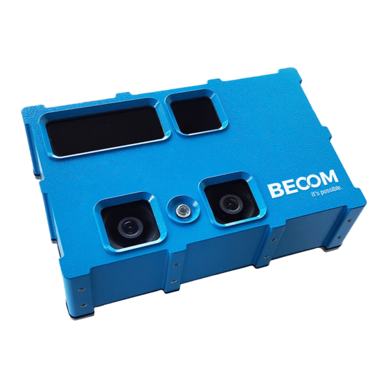
Hardware User Manual - TOREO-P650 Last change: 6 September 2021/Version 1 2 TOREO-P650 Components Figure 2-1 TOREO-P650 components (frontside) Figure 2-2 TOREO-P650 components (backside) Illumination window b. ToF sensor window RGB sensors d. Status LED © BECOM Systems 2021 8 | 25... - Page 9 Hardware User Manual - TOREO-P650 Last change: 6 September 2021/Version 1 IP67 compliant M12 connector for power supply and I/Os IP67 compliant M12 connector for gigabit Ethernet Service opening Ethernet activity LED Ethernet link status LED © BECOM Systems 2021...
-
Page 10: Mechanical Description
Hardware User Manual - TOREO-P650 Last change: 6 September 2021/Version 1 3 Mechanical Description 3.1 Dimensions All dimensions are in mm, tolerance +/-0,2mm. 3.1.1 Front view 230,0 Figure 3-1: Front view dimensions 3.1.2 Long side view Mounting hole size: M4 ©... -
Page 11: Short Side View
Hardware User Manual - TOREO-P650 Last change: 6 September 2021/Version 1 10,0 66,5 76,5 66,5 10,0 Figure 3-2: Long side view with mounting holes dimensions 3.1.3 Short side view Mounting hole size: M4 13,0 27,2 Figure 3-3: Short side view ©... -
Page 12: Mount Spacing
The user is responsible to take care for an appropriate cooling. To prevent the TOREO-P650 from overheating, it is recommended, to keep away nearby objects. This guarantees a constant airflow for proper cooling. This bounding box may be violated, when other cooling techniques are provided. -
Page 13: Interface Description
50V tolerant Accepts input voltage levels up to 50V (2.5V high voltage threshold) • 4.2 Connector Description The TOREO-P650 has two IP67 compliant connectors: An eight pole X-coded M12 connector used for gigabit ethernet communication, and a twelve pole M12 connector for power supply, and IOs. Figure 4-1 M12 ethernet connector pinout Pin No. -
Page 14: Figure 4-2 M12 Power And Io Connector Pinout
Hardware User Manual - TOREO-P650 Last change: 6 September 2021/Version 1 Pin No. Name Description Gigabit Ethernet Lane B negative Gigabit Ethernet Lane B positive Table 4.1: M12 ethernet connector description Figure 4-2 M12 power and IO connector Pinout Pin No. -
Page 15: Digital Inputs And Outputs
Hardware User Manual - TOREO-P650 Last change: 6 September 2021/Version 1 4.3 Digital Inputs and Outputs 4.3.1 Input Stage The implementation of the input stages for both digital inputs (reset and trigger) are shown in Figure 4-3. Figure 4-3 Input Stage The internal 10 kΩ... -
Page 16: Power Supply
Hardware User Manual - TOREO-P650 Last change: 6 September 2021/Version 1 4.4 Power supply The operational voltage range is 20 V to 30 V. To prevent internal components from being damaged, the power supply protection circuit turns off the power supply, if it is not within the specified boundaries. -
Page 17: Electrical Specification
Hardware User Manual - TOREO-P650 Last change: 6 September 2021/Version 1 5 Electrical Specification 5.1 Absolute maximum rating Stresses above the absolute maximum ratings listed in Table 5.1 may cause permanent damage to the device. These are stress ratings only and functional operation of the device at these conditions is not implied. Exposure to maximum rating conditions for extended periods may affect device reliability. -
Page 18: Software
6.3 Getting Started Software Development Example To facilitate the integration of the Argos module in your own application a getting started example will be available on our download site. Please refer to our support site http://systems.becom-group.com/support. © BECOM Systems 2021... -
Page 19: Appendix
Hardware User Manual - TOREO-P650 Last change: 6 September 2021/Version 1 7 Appendix 7.1 Operating Conditions 7.1.1 Input current The average input current depends on the selected frame-rate (fps) and the integration time (t ). The following figure shows typical values. The values on the x axis shows the FITP which has been calculated with the following equation: ��������... -
Page 20: Optical Characteristics
Hardware User Manual - TOREO-P650 Last change: 6 September 2021/Version 1 7.2 Optical Characteristics Symbol Parameter Typical Unit #LDs Amount of VCSEL laser diodes Λ Centroid-Wavelength of Illumination CENTROID Δλ Spectral Bandwidth Radiant intensity W/sr FoV-ToF Horizontal Field of View... -
Page 21: Accuracy
Hardware User Manual - TOREO-P650 Last change: 6 September 2021/Version 1 Figure 7-3: Precision 7.3.3 Accuracy The following figures has been determined by a frame-rate of 30fps and an integration time of 3,5ms with a reflectivity of 90%. Figure 7-4: Accuracy 7.4 Sensor Location... -
Page 22: Support
Hardware User Manual - TOREO-P650 Last change: 6 September 2021/Version 1 8 Support 8.1.1 General Support General support for products can be found at BECOM Systems’ support site Support Link http://systems.becom-group.com/support 8.1.2 Contact BECOM Systems GmbH Email: support.systems@becom-group.com Tel. +43 1 9142091 0 ©... -
Page 23: Product History
9.3.1 TOREO-P650 Version Type Release date V1.0.0 (X-Grade) September 2021 Table 9-3: Overview TOREO-P650 product changes Note Please refer to our support site for additional information about product changes. 9.4 Anomalies Applies to Date Description V1.0.0 No anomalies reported yet. -
Page 24: Document Revision History
Hardware User Manual - TOREO-P650 Last change: 6 September 2021/Version 1 10 Document Revision History Version Date Document Revision 2021 09 02 First preliminary of the document Table 10-1: Revision history © BECOM Systems 2021 24 | 25... -
Page 25: A List Of Figures And Tables
Last change: 6 September 2021/Version 1 A List of Figures and Tables Figures Figure 2-1 TOREO-P650 components (frontside) ................................8 Figure 2-2 TOREO-P650 components (backside) ................................8 Figure 3-1: Front view dimensions ......................................10 Figure 3-2: Long side view with mounting holes dimensions ..........................11 Figure 3-3: Short side view ...........................................
Need help?
Do you have a question about the TOREO-P650 and is the answer not in the manual?
Questions and answers