Advertisement
Quick Links
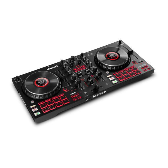
MixTrack Platinum FX
This document contains sensitive proprietary information.
All recipients must have a current non-disclosure agreement on file
with Numark.
Do not make illegal copies of this document.
The information in this document contains privileged and confidential information. It is intended only for the use of
those authorized by Numark. If you are not the authorized, intended recipient, you are hereby notified that any review,
dissemination, distribution or duplication of this document is strictly prohibited. If you are not authorized, please
contact Numark and destroy all copies of this document. You may contact Numark at support@numark.com.
© Copyright Numark
Confidential
Numark
[NKCH]
Service Manual
v1.0
2020-03-19
ATTENTION!
Numark Service Manual
Advertisement

Related Manuals for Numark MixTrack Platinum FX


Summary of Contents for Numark MixTrack Platinum FX
- Page 1 The information in this document contains privileged and confidential information. It is intended only for the use of those authorized by Numark. If you are not the authorized, intended recipient, you are hereby notified that any review, dissemination, distribution or duplication of this document is strictly prohibited. If you are not authorized, please contact Numark and destroy all copies of this document.
- Page 2 As the owner of the copyright to the Manual, Numark does not give you the right to copy the Manual, and you agree not to copy the Manual without the written authorization of Numark. Numark has no obligation to provide to you any correction of, or supplement to, the Manual, or any new or superseding version thereof.
- Page 3 ALL REPAIRS DONE BY ANY ENTITY OTHER THAN AN AUTHORIZED NUMARK SERVICE CENTER SHALL BE SOLELY THE RESPONSIBILITY OF THAT ENTITY, AND NUMARK SHALL HAVE NO LIABILITY TO THAT ENTITY OR TO ANY OTHER PARTY FOR ANY REPAIRS BY THAT ENTITY.
- Page 4 The product is exposed to water or excessive moisture, The AC power supply plug or cord is damaged, The product shows an inappropriate change in performance or does not operate normally, or The enclosure of the product has been damaged. Confidential Numark Service Manual...
-
Page 5: Specification
SERVICE MANUAL MODEL: MIXTRACKPLATINUMFX SPECIFICATION FUNCTION 1. UI Browser-----------------A standard detented encoder with push switch is used to navigate through the software 2. Master Volume------------Controls the gain of the master outputs. 3. Gain-------------------------This pot controls the gain for its associated channel on the mixer. 4. - Page 6 20. Sync-----------------------This control sends a momentary MIDI message. This control is used to force the track to align with the other deck’s tempo and phase. It is up to the software to either hard align or gently nudge it into place, depending on the Smart or Simple Sync chosen from the settings. The LED for this control will light when active.
-
Page 7: Disassembly Procedures
DISASSEMBLY PROCEDURES 1. REMOVAL OF THE B CABINET .(Fig1) (A) TAKE OUT THE 5 PCS VR CAP AND 17 PCS KNOB FROM OF CABINET. (B) TAKE OUT THE 14 PCS SCREWS FROM OF BOTTOM CHASSIS. Fig.1... - Page 8 2. REMOVAL PCB ASSEMBLY. (Fig. 2) (A) REMOVE THE 4 PCS SCREWS AND 2 PCS CONNECTORS BEFORE REMOVAL OF TOGGLE SW PCB DIP ASSEMBLY. (B) REMOVE THE 2 PCS SCREWS AND 1 PC CONNECTOR BEFORE REMOVAL OF IC VR PCB DIP ASSEMBLY. (C)REMOVE THE 6 PCS SCREWS AND 2 PCS CONNECTORS BEFORE REMOVAL OF LEFT&...
- Page 9 3. REMOVAL OF 3.5 INCH PCB ASSEMBLY. (Fig.3) (A) TAKE APART THE 2 PCS WHEEL PLATE. (B) REMOVE THE 12 PCS SCREWS BEFORE REMOVAL OF WHEEL FIXED HOLDER. (C) REMOVE 2 PCS NUT(M16) AND 4 PCS SCREWS AND 2 PCS C RING BEFORE REMOVAL OF TFT HOLDER.
- Page 15 0.1 PNKCHMAR01/06 Pack Assembly ..2 CGNKCH310MAR01 Inner Box ..2 CTNKCH513MAR01 Carton ..2 GEMAR118 Down Load Card ..2 LAC67MAR1093 LOGO Label(Numark) ..2 OPNK14MAR13 Sa ety Manual(1372-H) ..2 OPNKCHMAR01 Instruction Book ..2 PE230370404B09A Pe Bag ..2 PLNKCH01 Poly Foam(Le t) ..2 PLNKCH02 Poly Foam(Right) ..2 SD630330024B09...
-
Page 16: Rotate Button
..2 SD630330024B09 So tsheet 0.1 PT1110631623 Button(Phone)(Printing) ..2 PT11106316 Button 0.1 PT1110644302 Button(+,-)(Printing) ..2 PT11106443 Button (two Button) 0.1 PT1110649601 KNOB (Painting) ..2 PT11106496 Knob(LRG) 0.1 PT11106555 Light Pipe(5) 0.1 PT1110657403 Button Assembly(SATIN) 0.1 PT1110658504 Button(SHIFT) Printing ..2 PT11106585 Button 0.1 PT1110659301 KNOB (Painting) ..2 PT11106593... - Page 17 0.1 TWPC19C01901 Main PCB Assembly ..2 TWPC19C01901T Main PCB SMT Integration Assem ...3 PC19C019 Main PCB ...3 TWPC19C019A01T Main PCB SMT Assembly ..4 AA822524X IC SN74HC165PW IC16,18,20 ..4 AL2-51-4403 TRANSISTOR 2N4403 PNP ..4 AL2-75-4344 IC CS4344-CZZ 24bit 192KHz Ste IC9,11 ..4 AL2-85-0403 IC TPS60403 C20,21,22,23,25,26,28,29,30,31,42,43,50...
- Page 18 L2,3,4,5,6,7,8,9,10,11,15,16,17,18,19,20, ..4 UH160808T-600Y BEAD 60 @100MHz 3A ±25% 0603 21,22,23 ..4 UHBLM18PG121SN1 Bead 120 ±25% 2A 0603 L1,12,13,14 ..4 XTM24000X8 Crystal 24MHz 3.2*2.5*1.0MM SMD XTM1 ...3 TWPC19C019D01T Left LCD PCB SMT Assembly ..4 CS104K5003X7R CCAP SMD 0.1uF/50V 10% 0603 X7R C2,4,5,7 ..4 CS104K5005X7R CCAP SMD 0.1uF/50V 10% 0805 X7R...
- Page 19 ..4 CS105K1603X7R CCAP SMD 1uF/16V 10% 0603 X7R C18,20 ..4 CS475K1605X5R CCAP SMD 4.7uF/16V 10% 0805 X5R ..4 CS561J5003NPO CCAP SMD 560pF/50V 5% 0603 NPO C5,10 ..4 DICM1213A01SO Diode ESD Protection Arrays CM1213A ..4 FCN1T1001602 FCN Down Touch ZIF SMD Pitch=1.0mm 16P FCN1 ..4 IC74HCT595D IC 74HCT595D...
- Page 20 ..4 RS510K10F03 RESISTOR 510K 1% SMD 0603 R202 ..4 TE6A2000502 (TE200) Pin Header 90° Pitch 2.0mm Single Row 5Pin SMD ...3 TWPC19C020D01T RCA PCB SMT Assembly ..4 AL2-51-4403 TRANSISTOR 2N4403 PNP Q302 ..4 CS101J5003NPO CCAP SMD 100pF/50V 5% 0603 NPO C302,303,304,305,306 ..4 CS105K1603X7R CCAP SMD 1uF/16V 10% 0603 X7R...
- Page 21 ..4 DIEN1N4148WSM HF Diode 1N4148 D700 ..4 DIENMMBD4148SE Diode Single MMBD4148SE 100V 2 D701 ..4 IC74LVC2G17DBV IC 74LVC2G17DBV IC700 ..4 ICLM393DR IC OPA LM393DR IC701 ..4 RS010K10F03 RESISTOR 10K 1% SMD 0603 R701,703,707,708,712 ..4 RS033210F03 RESISTOR 332 1% SMD 0603 R706,711 ..4 RS056010F03 RESISTOR 560 1% SMD 0603...
- Page 22 ENCODE SW+3.3V D+3.3V A+3.3V A+3.3V 0.1uF DMP3099L TLV1117LV33 WHEEL+3.3V 0.01uF D+5V D+3.3V 0.1uF ENC1 Vout SW+3.3V 0.1uF DGND DGND 0.1uF 2N4403 VR+3.3V 0.1uF 0.1uF 0.1uF 22uF/16V 0.1uF 47uF/6.3V BROWN D+3.3V 10uF AGND 0.1uF 0.01uF ICSTM32F411RCT6 DGND AGND BROWSE_L_1 47.5K 47.5K PC13 0.1uF BROWSE_L_2...
- Page 23 VR+3.3V D+3.3V +3.3V(Red) VR+3.3V DGND GND(Black) 10uF 0.1uF R103 LCD_RESET RESET(White) R104 I2C1_SCL SCL(Yellow) IC12 R105 MID-L BASS-R PITCH-L DRY/WET TREBLE-L LEVEL-L I2C1_SDA SDA(Green) 74HC4051 VR10 VR17 DGND DGND D+5V TP10 +5V(Blue) 0.1uF OUT/IN To Left LCD PCB C107 0.1uF 0.1uF 0.1uF 0.1uF...
- Page 24 LED+4.5V LOAD-1 SW+3.3V SW+3.3V C108 C109 0.1uF IC15 LOAD-2 R117 R118 R119 R120 R121 R122 R123 R124 R116 1.2K LED1 R125 LED2 ECHO 0.1uF R127 DGND R126 LED3 DELAY DGND SPI1_MOSI LED+4.5V R129 R128 LED4 FLANGER SPI3_MISO R131 R134 LED7 PHASER 49.9 SPI1_RC...
- Page 25 VDD-L 5V_VLCD-L TO Backlight TO Backlight UH160808T-601Y UH160808T-601Y BLACK BLUE VLCD RESET-L 0.1uF 10uF 0.1uF 0.1uF 10uF 0.1uF 20Ω WHITE RESET SDA-L GREEN SCL-L YELLOW BLANK_IN-L BLANK_IN 4.7K 4.7K GND-L V1-L /VDD-L VLCD-L VLCD /RST-L /RST TO TN LCD TO TN LCD SA0-L SCL-L SDA-L...
- Page 26 VDD-R 5V_VLCD-R TO Backlight TO Backlight UH160808T-601Y UH160808T-601Y BLACK BLUE VLCD RESET-R 0.1uF 10uF 0.1uF 0.1uF 10uF 0.1uF 20Ω WHITE RESET SDA-R GREEN SCL-R YELLOW BLANK_IN-R BLANK_IN 4.7K 4.7K GND-R V1-R /VDD-R VLCD-R VLCD /RST-R /RST TO TN LCD TO TN LCD SA0-R SCL-R SDA-R...
- Page 31 PAD1 SW+3.3V SW+3.3V PAD2 R-LED+4.5V R-LED+4.5V 1.2K LED1 SYNC-R 0.1uF 1.2K LED2 SYNC-R PAD3 DGND 1.2K LED3 CUE-R 0.1uF SPI3_SER 1.2K LED4 CUE-R 49.9 1.2K LED5 PLAY-R PAD4 1.2K LED6 PLAY-R To MAIN PCB FCN1 DGND LED7 CUE-PAD-R SPI3_MOSI LED8 LOOP-PAD-R PAD5 LED9...
- Page 32 SW+3.3V. SW100 PAD1 SW+3.3V. R100 R101 R102 R103 R104 R105 R106 R107 C100 L-LED+4.5V SW101 PAD2 R108 1.2K LED100 SYNC-L R109 1.2K LED101 SYNC-L C101 0.1uF R110 1.2K LED102 CUE-L 0.1uF SW102 PAD3 .DGND IC100 R111 1.2K LED103 CUE-L R112 R113 1.2K LED104...
- Page 33 USB JACK To MAIN PCB TE3 VBUS. Vbus UGND R210 R211 UGND D201 D202 USB200 TE200 C201 0.1uF D200 R200 NUP2201MR6 C200 0.1uF DGND. PGND. AGND DGND. DGND. R201 R202 510K A+4V. 1Ω C202 2.2uF C203 100pF IC200C AGND ICNJM-2114M TE201 To MIC VR PCB TE500 C204...
- Page 34 R300 10K IC300B R301 10K Line-out R R302 MASTER-R. MASTER OUT Line-out L ICNJM-2114M R303 2.4K JK300A AGND. C303 C302 R304 100pF 100pF To USB PCB FCN200 JK4130-07520001 Q300 2SD2114KSM JK300B A+4V AGND. AGND AGND. D302 D303 A-4V AGND R305 2.4K R306 10K R307 MASTER-L.
- Page 35 To RCA PCB FCN301 JK400 MUTE R400 33Ω HP-L HP-L AGND R401 33Ω HP-R HP-R D400 D401 FCN400 R402 R403 SP400 SP401 C400 C401 Q400 Q401 100P 100P JK-3537 2SD2114KSM 2SD2114KSM HP OUT HAGND JK401 SP402 SP403 JY6317-02-030 HAGND Title: NKCJ/NKCH HP-PC19C020E Size Number...
- Page 36 To USB PCB TE201 VR500 C500 TE500 0.1uF(DNS) Title: NKCJ/NKCH MIC-PC19C020F Size Number Revision 2020/02/10 Date : Sheet File Name: Design By : Approval Check Design DATE Description...
- Page 37 .WHEEL+3.3V R600 12.1K R601 D600 C600 0.1uF JOGR-2 1N4148 R602 TCH_R_SEN 49.9K JOGR-1 .WHEEL+3.3V C605 .WHEEL+3.3V RSDGND 100pF(DNS) IC600B IC600A C601 0.1uF R603 R604 D602 D601 Q600 BAV99 MBT4401 MMBD4148SE PLATTEER TOUCH INPUT R SEN600 DIPH574 TP600 C602 0.1uF(DNS) .WHEEL+3.3V R605 R606 D603...
- Page 38 WHEEL+3.3V R700 12.1K R701 D700 C700 0.1uF 1N4148 WHEEL+3.3V JOGL-2 R702 TCH_L_SEN WHEEL+3.3V 49.9K LSDGND IC700C C701 JOGL-1 C705 0.1uF WHEEL+3.3V 100pF(DNS) C702 0.1uF IC700B IC700A D702 R703 R704 BAV99 D701 LSDGND Q700 MMBD4148SE PLATTEER TOUCH INPUT L MBT4401 SEN700 DIPH574 TP700 C703...
Need help?
Do you have a question about the MixTrack Platinum FX and is the answer not in the manual?
Questions and answers