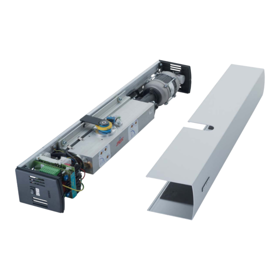
GEZE TSA 160 NT Mounting And Service Instructions
Automatic drive for swing doors
Hide thumbs
Also See for TSA 160 NT:
- Installation and service instructions manual (40 pages) ,
- Manual (16 pages)

Related Manuals for GEZE TSA 160 NT


Summary of Contents for GEZE TSA 160 NT
- Page 1 TSA 160 NT GB Mounting and service instructions TSA 160 NT F TSA 160 NT -IS TSA 160 NT Invers TSA 160 NT Z TSA 160 NT Z Invers TSA 162 Automatic drive for swing doors...
-
Page 2: Table Of Contents
Extension TSA 160 NT F and TSA 160 NT F -IS............................. 23 Extension of integrated closing sequence control unit TSA 160 NT -IS, TSA 160 NT F -IS, TSA 160 NT Z -IS ....23 Electrical mounting and device settings...................... 26 Mains connection...................................... -
Page 3: Symbols And Means Of Representation
TSA 160 NT and variants Symbols and means of representation Symbols and means of representation Warnings In these instructions, warnings are used to warn against material damage and injuries. Always read and observe these warnings. Observe all the measures that are marked with the warning symbol and warning word. -
Page 4: Safety
Safety 3. 1 Intended use The TSA 160 NT swing door drives are designed for the automatic opening and closing of swing-door single ac- tion doors. The above-mentioned door drive is suitable for use: solely for use in dry rooms... -
Page 5: Safety-Conscious Working
Use only the most recent versions. Transportation and storage CAUTION! Damage to the TSA 160 NT swing door drive through hard knocks and falls! Do not throw or let drop the TSA 160 NT. Store dry. Protect from moisture during transportation and storage. -
Page 6: Product Description
Single-leaf or double-leaf with intermediate cover or continuous cover. The swing door drive of the TSA 160 NT operates electro-hydraulically when opening the door. During the open- ing process a spring stores the energy required for closing. The closing process is controlled hydraulically. -
Page 7: Basic Structure
TSA 160 NT and variants Product description Basic structure Drive TSA 160 NT EN 3–6 Side panel Opening speed (ÖG) Base plate (at Invers drives: closing speed (SG)) Controller Drive shaft Hydraulic cylinder Latching setting (SE) Information plate (not at Invers drives) - Page 8 Product description TSA 160 NT and variants Drive TSA 160 NT EN 7 Side panel Opening speed (ÖG) Base plate (at Invers drives: closing speed (SG)) Controller Drive shaft Hydraulic cylinder Latching setting (SE) Information plate (not at Invers drives)
-
Page 9: Types Of Mounting, Stops
Types of mounting, stops Types of mounting, stops 7. 1 Single-leaf The TSA 160 NT allows the following types of stop, each for doors DIN left and doors DIN right: Hinge side Opposite hinge side Roller guide rail Link arm... -
Page 10: Mounting
Danger of injury through falling components! Unsecured components may fall down when under load. When mounting the TSA 160 NT swing door drive ensure that the substructure ensures secure fastening of the drive. Use suitable means of fastening such as anchors, rivet nuts, etc. -
Page 11: Conversion To Din Left
Mounting the stop bu er on the oor. Conversion to DIN left State of delivery is DIN right. If required the drive can be converted on site to DIN left. 8.2. 1 TSA 160 NT / TSA 160 NT Z Invers DIN right DIN left Procedure Screw o the limit switch (2), screw o the limit switch bar (4). - Page 12 Mounting TSA 160 NT and variants 8.2.2 TSA 160 NT Z / TSA 160 NT Invers State of delivery is DIN right. If required the drive can be converted on site to DIN left. DIN right 3 4 5 DIN left Procedure Screw o the limit switch (2), screw o the limit switch bar (4).
-
Page 13: Preparation Of Installation
Opening angle depending on the type of mounting A stop bu er is imperative if a TSA 160 NT Invers / TSA 160 NT Z Invers is used. A stop bu er is recommended if a TSA 160 NT / TSA 160 NT Z is used. -
Page 14: Mounting Dimensions For The Mounting Types
Mounting TSA 160 NT and variants Mounting dimensions for the mounting types The top of the door must be aligned exactly horizontally, both in the closed and in the open position. Use the correct tting template in accordance with the mounting type. - Page 15 TSA 160 NT and variants Mounting Fixing with mounting plate 6 5 0 487 . 5 3 2 5 16 2 . 5 3 3 5 5 8 7 Dimensional reference = hinge middle Ø 20, concealed cable routing Fitting hole Ø 8 Fitting hole Ø...
- Page 16 Mounting TSA 160 NT and variants 8.4.2 Transom mounting hinge side with roller guide rail (single-leaf, pulling) Observe drilling template: DIN left and DIN right mirrored. Drill both holes for the concealed cable path. Use rivet nuts, anchors bolts or equivalent fastening material.
- Page 17 TSA 160 NT and variants Mounting With 24 mm axial extension Without axial extension 8.4.3 Transom mounting opposite hinge side with link arm (dual-leaf, pushing) Observe drilling template: DIN left and DIN right mirrored. Drill both holes for the concealed cable path.
- Page 18 Mounting TSA 160 NT and variants Fixing with mounting plates 487.5 487.5 162.5 162.5 Dimensional reference = hinge middle Fixed leaf Ø 20, concealed cable routing Moving leaf Fixing with continuous mounting plate B /2 487.5 487.5 162.5 162.5 Dimensional reference = hinge middle Fixed leaf Ø...
- Page 19 TSA 160 NT and variants Mounting With 24 mm axial extension Without axial extension 8.4.4 Transom mounting hinge side with roller guide rail (dual-leaf, pulling) Observe drilling template: DIN left and DIN right mirrored. Drill both holes for the concealed cable path.
- Page 20 Mounting TSA 160 NT and variants Fixing with mounting plates 487.5 487.5 162.5 162.5 Dimensional reference = hinge middle Fixed leaf Ø 20, concealed cable routing Moving leaf Fixing with continuous mounting plate 487.5 487.5 162.5 162.5 Dimensional reference = hinge middle Fixed leaf Ø...
-
Page 21: Mounting The Drive
TSA 160 NT and variants Mounting With 24 mm axial extension Without axial extension 12 0 Mounting the drive Delivery only as DIN right. If necessary convert to DIN left. During mounting ensure that the connection cables are not pinched. - Page 22 TSA 160 NT and variants 8.5. 1 Mounting the link arm (drive on opposite hinge side, pushing) TSA 160 NT / TSA 160 NT Z Invers The door drive is mounted true-sided when the controller (6) points to the door pivot point.
-
Page 23: Extension Tsa 160 Nt F And Tsa 160 Nt F -Is
Extension TSA 160 NT F and TSA 160 NT F -IS The automatic systems TSA 160 NT F and TSA 160 NT F-IS are automatic swing door drives with an integrated hold-open device for re-proof doors, smoke-proof doors and doors that have to be self-closing (ends). They are part of a hold-open system. - Page 24 Mounting TSA 160 NT and variants Insert the wire rope (4) in the IS block (moving leaf) and fasten it with the clamping screw (14). Mounting on the xed leaf drive Slide the cam plate (2) onto the lever of the xed leaf drive (3) and premount with the clamping screws (1) as shown.
- Page 25 TSA 160 NT and variants Mounting Guide the wire rope (4) through the spindle (7). 9 0 ° Lay the release rocker (10) against the cam plate (2). The release rocker has it maximum de ection in this position. Pull the wire rope (4) tight and clamp tight with the clamping screw (7).
-
Page 26: Electrical Mounting And Device Settings
Electrical mounting and device settings TSA 160 NT and variants Carry out mounting of the link arm or roller guide rail at the moving leaf, see Section 8.5.1 or 8.5.2. Check the IS function: Open both leaves manu- ally and then release. -
Page 27: Settings
In the case of 2-leaf systems the blue cam plate (1) at the moving leaf drive and at the xed leaf drive have to be set. 9.2.2 Setting the limit switch at TSA 160 NT Invers Factory setting: 0° door opening angle. Hold the door in the closed position. - Page 28 Electrical mounting and device settings TSA 160 NT and variants 9.2.4 Closing torque for TSA160NT F and guide values for other drives The door closer power size (closing force of the closer) depends on the door width. The door leaf widths and door closer power sizes speci ed in the EN 1154 are binding for the TSA 160NT F. EN 1154 is a guide value for all other drives.
- Page 29 TSA 160 NT and variants Electrical mounting and device settings 9.2.5 Speed adjustment For 2-leaf systems the integrated closing sequence control ensures that the moving leaf begins its closing proc- ess approx. 1.5 s after the xed leaf. The speeds have to be set so that the xed leaf is closed rst.
-
Page 30: Final Check
Check the correct mounting and closing sequence control (for 2-leaf doors) in manual operation. For TSA 160 NT F: Open the door(s), check the closing speed and latching action and if necessary adjust. Checking of the valve settings is recommended for all the other drive types Switch the power supply back on or plug the connector back in. -
Page 31: Service
Checking of the fastening, setting and function of the control elements Preventative maintenance of the external devices, if necessary adjustment, functional check and cleaning Checking of safety of the entire system 11.3 Repairs Any repairs are to be carried out by GEZE or quali ed personnel authorised by GEZE. - Page 32 O ce Nr. 5201-5203 Baltic States 107076 Moskau Blenheim Way Tel. +65-6846 1338 GEZE GmbH Baltic States o ce Tel. +7 (0) 49 55 89 90 52 Fradley Park Fax +65-6846 9353 Dzelzavas iela 120 S Fax +7 (0) 49 55 89 90 51 Lich eld E-Mail: gezesea@geze.com.sg...
Need help?
Do you have a question about the TSA 160 NT and is the answer not in the manual?
Questions and answers