
Related Manuals for Daikin VRV system FXMQ200AXVMB


Summary of Contents for Daikin VRV system FXMQ200AXVMB
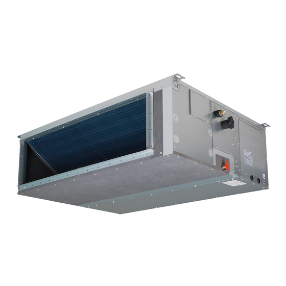
- Page 1 Installer and user reference guide VRV system air conditioner FXMQ200AXVMB FXMQ250AXVMB...
-
Page 2: Table Of Contents
Table of contents Table of contents 1 About the documentation About this document ..............................Meaning of warnings and symbols..........................2 General safety precautions For the installer ................................2.1.1 General ................................2.1.2 Installation site ............................... 2.1.3 Refrigerant — in case of R410A or R32......................2.1.4 Electrical ................................. - Page 3 Table of contents 15 About the units and options 15.1 Identification ................................... 38 15.1.1 Identification label: Indoor unit ........................38 15.2 About the indoor unit ..............................38 15.3 System layout.................................. 38 15.4 Combining units and options............................39 15.4.1 Possible options for the indoor unit....................... 39 16 Unit installation 16.1 Preparing the installation site............................
-
Page 4: About The Documentation
The original documentation is written in English. All other languages are translations. Technical engineering data ▪ A subset of the latest technical data is available on the regional Daikin website (publicly accessible). ▪ The full set of latest technical data is available on the Daikin Business Portal (authentication required). - Page 5 About the documentation DANGER: RISK OF ELECTROCUTION Indicates a situation that could result in electrocution. DANGER: RISK OF BURNING/SCALDING Indicates a situation that could result in burning/scalding because of extreme hot or cold temperatures. DANGER: RISK OF EXPLOSION Indicates a situation that could result in explosion. WARNING Indicates a situation that could result in death or serious injury.
-
Page 6: General Safety Precautions
Improper installation or attachment of equipment or accessories could result in electrical shock, short-circuit, leaks, fire or other damage to the equipment. ONLY use accessories, optional equipment and spare parts made or approved by Daikin. WARNING Make sure installation, testing and applied materials comply with applicable legislation (on top of the instructions described in the Daikin documentation). -
Page 7: Installation Site
General safety precautions ▪ Instructions for shutting down the system in case of an emergency ▪ Name and address of fire department, police and hospital ▪ Name, address and day and night telephone numbers for obtaining service In Europe, EN378 provides the necessary guidance for this logbook. 2.1.2 Installation site ▪... - Page 8 General safety precautions WARNING ALWAYS recover the refrigerant. Do NOT release them directly into the environment. Use a vacuum pump to evacuate the installation. WARNING Make sure there is no oxygen in the system. Refrigerant may ONLY be charged after performing the leak test and the vacuum drying.
-
Page 9: Electrical
General safety precautions ▪ Charge the refrigerant in liquid form. Adding it in gas form may prevent normal operation. CAUTION When the refrigerant charging procedure is done or when pausing, close the valve of the refrigerant tank immediately. If the valve is NOT closed immediately, remaining pressure might charge additional refrigerant. - Page 10 General safety precautions CAUTION ▪ When connecting the power supply: connect the earth cable first, before making the current-carrying connections. ▪ When disconnecting the power supply: disconnect the current-carrying cables first, before separating the earth connection. ▪ The length of the conductors between the power supply stress relief and the terminal block itself MUST be as such that the current-carrying wires are tautened before the earth wire is in case the power supply is pulled loose from the stress relief.
-
Page 11: Specific Installer Safety Instructions
Specific installer safety instructions 3 Specific installer safety instructions Always observe the following safety instructions and regulations. Unit installation (see "16 Unit installation" [ 40]) CAUTION Appliance NOT accessible to the general public, install it in a secured area, protected from easy access. This unit, both indoor and outdoor, is suitable for installation in a commercial and light industrial environment. - Page 12 Specific installer safety instructions WARNING ▪ If the power supply has a missing or wrong N-phase, equipment might break down. ▪ Establish proper earthing. Do NOT earth the unit to a utility pipe, surge absorber, or telephone earth. Incomplete earthing may cause electrical shock. ▪...
-
Page 13: For The User
For the user FXMQ-A Installer and user reference guide VRV system air conditioner 4P701548-1 – 2022.07... -
Page 14: User Safety Instructions
User safety instructions 4 User safety instructions Always observe the following safety instructions and regulations. 4.1 General WARNING If you are NOT sure how to operate the unit, contact your installer. WARNING This appliance can be used by children aged from 8 years and above and persons with reduced physical, sensory or mental capabilities or lack of experience and knowledge if they have been given supervision or instruction concerning... -
Page 15: Instructions For Safe Operation
User safety instructions ▪ Units are marked with the following symbol: This means that electrical and electronic products may NOT be mixed with unsorted household waste. Do NOT try to dismantle the system yourself: dismantling the system, treatment of the refrigerant, of oil and of other parts MUST be done by an authorised installer and MUST comply with applicable legislation. - Page 16 User safety instructions CAUTION ▪ NEVER touch the internal parts of the controller. ▪ Do NOT remove the front panel. Some parts inside are dangerous to touch and appliance problems may happen. For checking and adjusting the internal parts, contact your dealer. WARNING This unit contains electrical and hot parts.
- Page 17 User safety instructions "10 Maintenance and service" [ 26]) Maintenance and service (see CAUTION: Pay attention to the fan! It is dangerous to inspect the unit while the fan is running. Make sure to turn OFF the main switch before executing any maintenance task. CAUTION Do NOT insert fingers, rods or other objects into the air inlet or outlet.
- Page 18 User safety instructions CAUTION Turn off the unit before cleaning the air outlet. WARNING Do NOT let the indoor unit get wet. Possible consequence: Electrical shock or fire. About the refrigerant (see "10.5 About the refrigerant" [ 28]) WARNING ▪ The refrigerant in the system is safe and normally does NOT leak.
-
Page 19: About The System
About the system 5 About the system WARNING ▪ Do NOT modify, disassemble, remove, reinstall or repair the unit yourself as incorrect dismantling or installation may cause an electrical shock or fire. Contact your dealer. ▪ In case of accidental refrigerant leaks, make sure there are no naked flames. The refrigerant itself is entirely safe, non-toxic and non-combustible, but it will generate toxic gas when it accidentally leaks into a room where combustion air from fan heaters, gas cookers, etc. -
Page 20: Information Requirements For Fan Coil Units
Total electric power input elec Sound power level (cooling) dB(A) Sound power level (heating) dB(A) Contact details: DAIKIN INDUSTRIES CZECH REPUBLIC s.r.o. U Nové Hospody 1/1155, 301 00 Plzeň Skvrňany, Czech Republic FXMQ200 0.540 FXMQ250 21.1 31.5 0.650 FXMQ-A... -
Page 21: User Interface
User interface 6 User interface CAUTION ▪ NEVER touch the internal parts of the controller. ▪ Do NOT remove the front panel. Some parts inside are dangerous to touch and appliance problems may happen. For checking and adjusting the internal parts, contact your dealer. -
Page 22: Before Operation
Before operation 7 Before operation CAUTION "4 User safety instructions" [ 14] to acknowledge all related safety instructions. This operation manual is for the following systems with standard control. Before initiating operation, contact your dealer for the operation that corresponds to your system type and mark. -
Page 23: Operation
Operation 8 Operation 8.1 Operation range INFORMATION For the operation limits see the technical data of the connected outdoor unit. 8.2 About operation modes INFORMATION Depending on the installed system, some operation modes will not be available. ▪ The air flow rate may adjust itself depending on the room temperature or the fan may stop immediately. -
Page 24: Special Heating Operation Modes
Operation 8.2.2 Special heating operation modes Operation Description Defrost To prevent a loss of heating capacity due to frost accumulation in the outdoor unit, the system will automatically switch to defrost operation. During defrost operation, the indoor unit fan will stop operation, and the following icon will appear on the home screen: The system will resume normal operation after approximately 6... -
Page 25: Energy Saving And Optimum Operation
Energy saving and optimum operation 9 Energy saving and optimum operation CAUTION NEVER expose little children, plants or animals directly to the airflow. NOTICE Do NOT place objects below the indoor and/or outdoor unit that may get wet. Otherwise condensation on the unit or refrigerant pipes, air filter dirt or drain blockage may cause dripping, and objects under the unit may get dirty or damaged. -
Page 26: Maintenance And Service
Maintenance and service 10 Maintenance and service 10.1 Precautions for maintenance and service CAUTION "4 User safety instructions" [ 14] to acknowledge all related safety instructions. NOTICE NEVER inspect or service the unit by yourself. Ask a qualified service person to perform this work. However, as end user, you may clean the air filter and air outlet. NOTICE Maintenance MUST be done by an authorised installer or service agent. -
Page 27: Cleaning The Air Filter And Air Outlet
Maintenance and service 10.2 Cleaning the air filter and air outlet CAUTION Turn off the unit before cleaning the air filter and air outlet. NOTICE ▪ Do NOT use gasoline, benzene, thinner polishing powder or liquid insecticide. Possible consequence: Discoloration and deformation. ▪... -
Page 28: Maintenance Before A Long Stop Period
Maintenance and service Clean with a soft cloth. If it is difficult to remove stains, use water or a neutral detergent. 10.3 Maintenance before a long stop period E.g., at the end of the season. ▪ Let the indoor units run in fan only operation for about half a day in order to dry the interior of the units. - Page 29 Maintenance and service WARNING ▪ The refrigerant in the system is safe and normally does NOT leak. If the refrigerant leaks in the room, contact with a fire of a burner, a heater or a cooker may result in a harmful gas. ▪...
-
Page 30: Troubleshooting
Troubleshooting 11 Troubleshooting If one of the following malfunctions occur, take the measures shown below and contact your dealer. WARNING Stop operation and shut OFF the power if anything unusual occurs (burning smells etc.). Leaving the unit running under such circumstances may cause breakage, electrical shock or fire. -
Page 31: Symptoms That Are Not System Malfunctions
Troubleshooting Malfunction Measure The system operates but ▪ Check if air inlet or outlet of outdoor or indoor cooling or heating is unit is not blocked by obstacles. Remove any insufficient. obstacles and make sure the air can flow freely. ▪... -
Page 32: Symptom: White Mist Comes Out Of A Unit (Indoor Unit)
Troubleshooting 11.1.2 Symptom: White mist comes out of a unit (Indoor unit) ▪ When humidity is high during cooling operation. If the interior of an indoor unit is extremely contaminated, the temperature distribution inside a room becomes uneven. It is necessary to clean the interior of the indoor unit. Ask your dealer for details on cleaning the unit. -
Page 33: Relocation
Relocation 12 Relocation Contact your dealer to remove and reinstall the entire unit. Moving units requires technical expertise. FXMQ-A Installer and user reference guide VRV system air conditioner 4P701548-1 – 2022.07... -
Page 34: Disposal
Disposal 13 Disposal NOTICE Do NOT try to dismantle the system yourself: dismantling of the system, treatment of the refrigerant, oil and other parts MUST comply with applicable legislation. Units MUST be treated at a specialised treatment facility for reuse, recycling and recovery. FXMQ-A Installer and user reference guide VRV system air conditioner... -
Page 35: For The Installer
For the installer FXMQ-A Installer and user reference guide VRV system air conditioner 4P701548-1 – 2022.07... -
Page 36: About The Box
About the box 14 About the box Keep the following in mind: ▪ At delivery, the unit MUST be checked for damage and completeness. Any damage or missing parts MUST be reported immediately to the claims agent of the carrier. ▪... - Page 37 About the box 1× 1× 8× 49× 2× 1× 1× 2× 1× a Installation and operation manual b General safety precautions c Washers for hanger bracket d Screws for duct flanges (M5×12) e Hexagon head bolt (M10×40) f Attached piping with sealing g Tie wrap h Spring washer i Air outlet flange (under the indoor unit)
-
Page 38: About The Units And Options
About the units and options 15 About the units and options In this chapter 15.1 Identification................................... 15.1.1 Identification label: Indoor unit ..........................15.2 About the indoor unit................................15.3 System layout..................................15.4 Combining units and options..............................15.4.1 Possible options for the indoor unit ........................15.1 Identification NOTICE When installing or servicing several units at the same time, make sure NOT to switch... -
Page 39: Combining Units And Options
About the units and options a Outdoor unit b Multi BS unit c Indoor unit d Remote controller (user interface) 15.4 Combining units and options INFORMATION Certain options may NOT be available in your country. 15.4.1 Possible options for the indoor unit Make sure you have the following mandatory options: ▪... -
Page 40: Unit Installation
Unit installation 16 Unit installation In this chapter 16.1 Preparing the installation site ..............................16.1.1 Installation site requirements of the indoor unit ....................16.2 Mounting the indoor unit............................... 16.2.1 Guidelines when installing the indoor unit......................16.2.2 Guidelines when installing the ducting........................16.2.3 Guidelines when installing the drain piping ...................... - Page 41 Unit installation NOTICE The equipment described in this manual may cause electronic noise generated from radio-frequency energy. The equipment complies to specifications that are designed to provide reasonable protection against such interference. However, there is no guarantee that interference will NOT occur in a particular installation. It is therefore recommended to install the equipment and electric wires in such a way that they keep a proper distance from stereo equipment, personal computers, etc.
-
Page 42: Mounting The Indoor Unit
Unit installation Service space and ceiling opening size Make sure ceiling opening is big enough to ensure a sufficient clearance for maintenance and service. Top view: a 1100 b ≥1143 (mm) a Ceiling opening b Service space c Inspection hatch (600×600 mm) INFORMATION Some options may require additional service space. - Page 43 Unit installation e 1028 a Nut (field supply) b Washer (accessories) c Hanger bracket d Double nut (field supply) e Suspension bolt pitch ▪ Install the unit temporarily. 1 Attach the hanger bracket to the suspension bolt. 2 Fix it securely. ▪...
-
Page 44: Guidelines When Installing The Ducting
Unit installation 2 Partially insert the first part of the air filter. 3 Align the middle part of the air filter with first part and push the 2 clips in place to lock the filter parts together. 4 Repeat the procedure for the last part of the filter. 5 Re-install the filter cover. -
Page 45: Guidelines When Installing The Drain Piping
Unit installation a Air inlet b Air outlet c Screws for duct flanges d Air outlet flange e Air inlet flange f Transportation case cover 1 Remove the air outlet flange from the transportation case cover. 2 Move and attach the air outlet flange to the air outlet side. 3 Fix the air outlet flange with the 34 screws for duct flanges (accessory). - Page 46 Unit installation ▪ Pipe size. Keep the pipe size equal to or greater than that of the connecting pipe (vinyl pipe of 25 mm nominal diameter and 32 mm outer diameter). ▪ Slope. Make sure the drain piping slopes down (at least 1/100) to prevent air from being trapped in the piping.
- Page 47 Unit installation a Indoor unit b BSP 1" internal thread c Adapter (field supply) d Metal clamp (field supply) e Insulation material for drain pipe (field supply) To check for water leaks The procedure differs depending on whether installation of the system is already completed.
- Page 48 Unit installation 5 Turn OFF the power. 6 Disconnect the electrical wiring. ▪ Remove the service cover. ▪ Disconnect the power supply. ▪ Disconnect the user interface. ▪ Reattach the service cover. When installation of the system is already completed 1 Start cooling operation (see the reference guide or the service manual of the user interface).
-
Page 49: Piping Installation
Piping installation 17 Piping installation In this chapter 17.1 Preparing refrigerant piping ..............................17.1.1 Refrigerant piping requirements ........................... 17.1.2 Refrigerant piping insulation..........................17.2 Connecting the refrigerant piping............................17.2.1 About connecting the refrigerant piping....................... 17.2.2 Precautions when connecting the refrigerant piping.................... 17.2.3 Guidelines when connecting the liquid piping ...................... -
Page 50: Refrigerant Piping Insulation
Piping installation 17.1.2 Refrigerant piping insulation ▪ Use polyethylene foam as insulation material: with a heat transfer rate between 0.041 and 0.052 W/mK (0.035 and 0.045 kcal/mh°C) with a heat resistance of at least 120°C ▪ Insulation thickness Pipe outer diameter (Ø ) Insulation inner diameter Insulation thickness (t) (Ø... -
Page 51: Precautions When Connecting The Refrigerant Piping
Piping installation 17.2.2 Precautions when connecting the refrigerant piping INFORMATION Also read the precautions and requirements in the following chapters: ▪ "2 General safety precautions" [ 6] ▪ "17.1 Preparing refrigerant piping" [ 49] DANGER: RISK OF BURNING/SCALDING NOTICE ▪ Do NOT use mineral oil on flared part. ▪... -
Page 52: Guidelines When Connecting The Liquid Piping
Piping installation 17.2.3 Guidelines when connecting the liquid piping INFORMATION To connect the liquid piping use flare connection. Take the following guidelines into account when connecting pipes: ▪ Coat the flare inner surface with ether oil or ester oil when connecting a flare nut. -
Page 53: Guidelines When Connecting The Gas Piping
Piping installation 3 Remove the flare nut from the stop valve and put the flare nut on the pipe. 4 Flare the pipe. Set exactly at the position as shown in the following figure. Flare tool for R410A or Conventional flare tool R32 (clutch type) Clutch type Wing nut type... -
Page 54: To Connect The Refrigerant Piping To The Indoor Unit
Piping installation ▪ Do NOT use flux when brazing copper-to-copper refrigerant piping. Use phosphor copper brazing filler alloy (BCuP-2: JIS Z 3264/, BCu 93P-710/795: ISO3677), which does not require flux. Flux has an extremely harmful influence on refrigerant piping systems. E.g., if a chlorine-based flux is used, it will cause pipe corrosion or, in particular, if the flux contains fluorine, it will deteriorate the refrigerant oil. - Page 55 Piping installation f Unit NOTICE Make sure to insulate all refrigerant piping. Any exposed piping might cause condensation. FXMQ-A Installer and user reference guide VRV system air conditioner 4P701548-1 – 2022.07...
-
Page 56: Electrical Installation
Electrical installation 18 Electrical installation In this chapter 18.1 About connecting the electrical wiring ..........................18.1.1 Precautions when connecting the electrical wiring ....................18.1.2 Guidelines when connecting the electrical wiring ....................18.1.3 Specifications of standard wiring components ..................... 18.2 To connect the electrical wiring to the indoor unit ....................... 18.1 About connecting the electrical wiring Typical workflow Connecting the electrical wiring typically consists of the following stages:... -
Page 57: Guidelines When Connecting The Electrical Wiring
Electrical installation WARNING ▪ If the power supply has a missing or wrong N-phase, equipment might break down. ▪ Establish proper earthing. Do NOT earth the unit to a utility pipe, surge absorber, or telephone earth. Incomplete earthing may cause electrical shock. ▪... -
Page 58: Specifications Of Standard Wiring Components
Electrical installation Wire type Installation method Single-core wire AA´ A´ a Curled single-core wire b Screw c Flat washer Stranded conductor wire with round crimp-style terminal a Terminal b Screw c Flat washer Allowed NOT allowed Tightening torques Wiring Screw size Tightening torque (N•m) Power supply cable... -
Page 59: To Connect The Electrical Wiring To The Indoor Unit
Electrical installation Component Class User interface cable 0.75 to 1.25 mm (2‑core wire) H05RN-F (60245 IEC 57) Length ≤500 m Recommended field fuse 6 A Residual current device Must comply with applicable legislation MCA=Minimum circuit ampacity. Stated values are maximum values (see electrical data of indoor unit for exact values). - Page 60 Electrical installation 70~90 10~15 a User interface cable and transmission cable b Power supply cable c Service cover with wiring diagram 5 Plastic clamp for tie wrap (for transmission cable): Pass tie wraps through the plastic clamps and fasten to fix the cables. 6 Cable clamp (for power supply cable): Fix the cable with the cable clamp.
- Page 61 Electrical installation TO IN/D TO OUT/D a Outdoor unit b Indoor unit c User interface d Most downstream indoor unit With BS unit TO IN/D TO OUT/D OUTDOOR UNIT INDOOR UNIT a Outdoor unit b BS unit c Indoor unit d User interface FXMQ-A Installer and user reference guide...
-
Page 62: Commissioning
19 Commissioning NOTICE General commissioning checklist. Next to the commissioning instructions in this chapter, a general commissioning checklist is also available on the Daikin Business Portal (authentication required). The general commissioning checklist is complementary to the instructions in this chapter and can be used as a guideline and reporting template during commissioning and hand-over to the user. -
Page 63: Checklist Before Commissioning
Commissioning 19.3 Checklist before commissioning 1 After the installation of the unit, check the items listed below. 2 Close the unit. 3 Power up the unit. You have read the complete installation and operation instructions described in the installer and user reference guide. Installation Check that the unit is properly installed, to avoid abnormal noises and vibrations when starting up the unit. -
Page 64: To Perform A Test Run
Commissioning 19.4 To perform a test run INFORMATION ▪ Perform the test run according to the instructions in the outdoor unit manual. ▪ The test run is only completed if there is no malfunction code displayed on the user interface or the outdoor unit 7‑segment display. ▪... -
Page 65: Configuration
Configuration 20 Configuration 20.1 Field setting Make the following field settings so that they correspond with the actual installation setup and with the needs of the user: ▪ External static pressure setting using: Airflow automatic adjustment setting User interface ▪ Air volume when thermostat control is OFF ▪... - Page 66 Configuration 1 Operate the unit in fan only mode prior to using the airflow automatic adjustment function. 2 Stop the air conditioning unit. 3 Set the value number “—“ to 03 for M 11(21) and SW 7. 4 Start the air conditioning unit. Result: The operation lamp lights up and the unit starts the fan operation for airflow automatic adjustment.
- Page 67 Configuration Setting: Air volume when thermostat control is OFF This setting must correspond with the needs of the user. It determines the fan speed of the indoor unit during thermostat OFF condition. 1 If you have set the fan to operate, set the air volume speed: If you want…...
- Page 68 Configuration When the remote controller thermostat sensor Then is… — Used in combination with indoor unit thermistor 10 (20) Not used (indoor unit thermistor only) Used exclusively Setting: Thermostat sensor in group control This setting must correspond with how/if the remote controller thermostat sensor is used in group control.
- Page 69 Configuration Setting: Auto-restart after power failure Depending on the needs of the user, you may disable/enable the automatic restart after a power failure. If you want auto-restart after power failure… Then — Disabled 12 (22) Enabled Setting: T1/T2 input setting Remote control is available by transmission the external input to the terminals T1 and T2 on the terminal block for the user interface and the transmission wiring.
-
Page 70: Hand-Over To The User
Hand-over to the user 21 Hand-over to the user Once the test run is finished and the unit operates properly, make sure the following is clear for the user: ▪ Make sure that the user has the printed documentation and ask him/her to keep it for future reference. -
Page 71: Troubleshooting
Troubleshooting 22 Troubleshooting 22.1 Solving problems based on error codes If the unit runs into a problem, the user interface displays an error code. It is important to understand the problem and to take measures before resetting an error code. This should be done by a licensed installer or by your local dealer. This chapter gives you an overview of most possible error codes and their descriptions as they appear on the user interface. -
Page 72: Disposal
Disposal 23 Disposal NOTICE Do NOT try to dismantle the system yourself: dismantling of the system, treatment of the refrigerant, oil and other parts MUST comply with applicable legislation. Units MUST be treated at a specialised treatment facility for reuse, recycling and recovery. FXMQ-A Installer and user reference guide VRV system air conditioner... -
Page 73: Technical Data
Technical data 24 Technical data ▪ A subset of the latest technical data is available on the regional Daikin website (publicly accessible). ▪ The full set of latest technical data is available on the Daikin Business Portal (authentication required). 24.1 Wiring diagram 24.1.1 Unified wiring diagram legend... - Page 74 Technical data Symbol Meaning AC*, CN*, E*, HA*, HE*, HL*, HN*, HR*, Connection, connector MR*_A, MR*_B, S*, U, V, W, X*A, K*R_*, NE D*, V*D Diode Diode bridge DIP switch Heater FU*, F*U, (for characteristics, refer to Fuse PCB inside your unit) Connector (frame ground) Harness H*P, LED*, V*L...
- Page 75 Technical data Symbol Meaning Thermo switch Residual current device Resistor Thermistor Receiver Limit switch Float switch S*NG Refrigerant leak detector S*NPH Pressure sensor (high) S*NPL Pressure sensor (low) S*PH, HPS* Pressure switch (high) S*PL Pressure switch (low) Thermostat S*RH Humidity sensor S*W, SW* Operation switch SA*, F1S...
-
Page 76: Glossary
Optional equipment Equipment made or approved by Daikin that can be combined with the product according to the instructions in the accompanying documentation. Field supply Equipment NOT made by Daikin that can be combined with the product according to the instructions in the accompanying documentation. - Page 80 4P701548-1 2022.07 Verantwortung für Energie und Umwelt...
Need help?
Do you have a question about the VRV system FXMQ200AXVMB and is the answer not in the manual?
Questions and answers