
Related Manuals for AEA PK-232

Summary of Contents for AEA PK-232
- Page 1 TECHNICAL REFERENCE MANUAL MODEL PK-232 DATA CONTROLLER ADVANCED ELECTRONICS APPLICATIONS, INC. (Preliminary Release)
- Page 2 However, there is no guarantee that interference will not occur in a particular installation. If this equipment does cause interference to radio or TV reception, which can be determined by turning the PK-232 on and off, the user is encouraged to try and correct the interference using one or more of the following measures: Reorient the antenna of the device receiving interference.
- Page 3 Remove the four screws from the sides and the two screws from the rear of the chassis. then lift off the PK-232's cover. Take care not to disturb the black or red wires that attach the bat- tery holder to the printed circuit board.
-
Page 4: Table Of Contents
PK-232 TECHNICAL MANUAL TABLE OF CONTENTS CHAPTER 1 – INTRODUCTION Paragraph Page Introduction ..................1-1 Scope ....................1-1 General Description ................1-1 Specifications ..................1-1 1.4.1 Operating Modes ..............1-2 1.4.2 Modem Characteristics ............1-2 1.4.3 Processor System ..............1-2 1.4.4... -
Page 5: Paragraph Page
4.3.2 OPMODE Response ..............4-7 4.3.3 Link Status Request Response ..........4-7 4.3.4 Call Sign Formats ..............4-7 Sending Data to the PK-232 ............... 4-8 4.4.1 Data Polling ................4-8 4.4.2 The HPOLL Command ............. 4-8 4.4.3 Special Case in AMTOR ............4-9 4.4.4... - Page 6 PK-232 TECHNICAL MANUAL CHAPTER 5 – MECHANICAL ASSEMBLY AND DIS ASSEMBLY Paragraph Page Cover Removal .................. 5-1 Circuit Board Removal ............... 5- Circuit Board Assembly ..............5-2 Cover Assembly ................5- CHAPTER 6 – ADJUSTMENTS Preliminary Setup ................6-1 Calibration Procedure ................ 6- 6.2.1...
-
Page 7: Introduction
The PK-232 sends and receives Morse Baudot and ASCII RTTY, facsimile, AMTOR/SITOR and AX.25 packet. The PK-232 converts these signals to ASCII data end sends the data to your terminal via an EIA standard RS-232 (CCITT V.24/V.28) serial port, and to your printer via a special Centronics-type parallel interface. -
Page 8: Modem Characteristics
PK-232 TECHNICAL MANUAL CHAPTER 1 – INTRODUCTION 1.4.2 Modem Characteristics Demodulator: Limiter-discriminator type, preceded by an eight-pole Chebyshev 0.5 dB ripple bandpass filter Receive bandpass: Automatically switched by operating mode VHF packet: Center frequency 1700 Hz, bandwidth 2600 Hz HF (except CW):... -
Page 9: Controls And Indicators
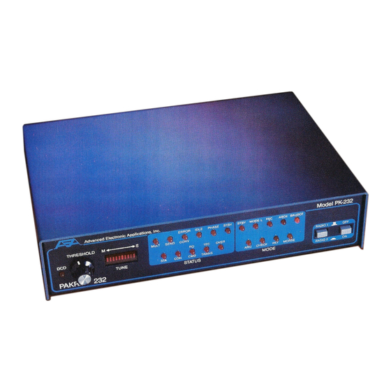
PK-232 TECHNICAL MANUAL CHAPTER 1 – INTRODUCTION 1.4.5 Controls and Indicators Front Panel Controls: Power Switch Radio Selector Switch Threshold Adjust Indicators: Ten-segment discriminator-type bargraph indicator for HF tuning. DCD LED (Data Carrier Detect) Status and Mode Indicators: Mode Group... -
Page 10: Chapter 2 - Functional Description
Power Distribution Input/Output (I/O) Each of these functional blocks has its own distinct functions. The following paragraphs de- scribe each section. Refer to the PK-232 Functional Block Diagram, Figure 1 in Appendix C, while reading these descriptions. 2.1.1 Analog Section The analog section consists of active filters, limiters, a threshold detector, DCD (Data Car- rier Detect and diode discriminator circuits. -
Page 11: Chapter 3 - Theory Of Operation
Please refer to APPENDIX C for the various diagrams used as reference in this chapter. 3.1.1 Block Diagrams Refer to the Functional Block Diagram, Figure 1 in APPENDIX C. Dashed lines separate the five sections of the PK-232. Each section will be described separately and is labeled as fol- lows: Analog Digital... -
Page 12: Analog Subsystem
CHAPTER 3 – THEORY OF OPERATION Analog Subsystem Each of the PK-232's operating modes requires different bandwidths, as well as varying AFSK tone and speed characteristics. The analog circuitry is adapted to these differences by using program-controlled switches to place precision resistors in parallel with the fixed com- ponents of the circuits. -
Page 13: Transmit Function
PK-232 TECHNICAL MANUAL CHAPTER 3 – THEORY OF OPERATION The tones processed by the resonators are rectified in a full-wave diode network formed by D19 and D20 for the MARK channel, and D22 and D23 for the SPACE chan- nel. The MARK signal is positive with respect to the voltage reference (VR); the SPACE signal is negative. -
Page 14: Memory
3.3.2 Memory The PK-232 memory consists of 48 kB of EPROM at U2 and U3, and 16 kB of static RAM at U4 and U5. U2 is a 27256 EPROM which occupies the 32 kB address space between $0000 and $7FFF. - Page 15 PK-232 TECHNICAL MANUAL CHAPTER 3 – THEORY OF OPERATION ––––––––––––––– Narrow shift FSK Wide shift FSK Parallel port A can be controlled by the user directly. Set ADDRESS to $BF0D and then read or write port A using the IO command.
-
Page 16: 8530 Scc Serial Communications Controller
Port A is the HDLC port for Packet-Radio. Port B is the RS-232 interface to the terminal. This chip receives address bits A0, A1 and A7 from the CPU. The PK-232 firmware ad- dresses the 8530 by forcing all other address bits high, yielding these addresses:... - Page 17 R146 (10 k) and C55 (47 µ). For this scheme to work properly, the DTRA output is toggled every pass trough the main loop of the PK-232 firmware. In order to make the 8530 and 8536 chips operate with the Z80A CPU, a state machine consisting of U9 (74LS164), U14 (74LS11) and U1 (74LS04) is used.
-
Page 18: Introduction To Host Mode
Why Do We Need a Host Mode ? You may wish to write a program that permits your computer to control your PK-232. You could write a program that provides a split screen with status windows. You might want to include a personal mailbox, a multi-user bulletin board system, an automatic calling rou- tine, with tutorials or help screens. -
Page 19: Entering Host Mode
PK-232 TECHNICAL MANUAL CHAPTER 4 – HOST MODE AND SPECIAL APPLICATIONS In Host mode, the PK-232 sends data to the computer only when the computer requests data. This feature is selectable by the user (see HPOLL below). 4.1.3 Entering Host Mode... -
Page 20: Host Mode Recovery
This occurs in either direction, from the computer to the PK-232 or from the PK-232 to the computer. 4.1.6 Host Mode Recovery If it becomes necessary to quit Host mode because of a problem on the RS-232 link, send any command, with TWO SOH characters to start the block. -
Page 21: Unsupported Commands
PK-232 TECHNICAL MANUAL CHAPTER 4 – HOST MODE AND SPECIAL APPLICATIONS 4.2.1 Unsupported Commands The PK-232 does not accept these commands in Hoste Mode: CALIBRATE – CONVERSE – CSTATUS – DISPLAY – HELP – TRANS 4.2.2 Host Mode Mnemonic Indicators Each command in the Host mode can be sent by issuing a unique mnemonic or abbrevia- tion in the form of a two-letter character group. -
Page 22: Connect And Disconnect
4.2.7 Interrogation or Querry Commands Querry commands are similar to the human or verbose mode in that the two-letter com- mand to the PK-232 is not followed by arguments, that is, the command is followed by ETB. PK-232 Responses The PK-232 always issues a response to each command. -
Page 23: Responses To Interrogation Or Query Commands
NOTE: Channel 'x' (0-9) refers to the Packet multi-connect channel that would be available in verbose (human) mode by using the CSWITCH character. Only channel 0 is used in all communications mode other than Packet mode. The PK-232's response structure is: where are the two-letter host command received from the computer, and... -
Page 24: Opmode Response
PK-232 TECHNICAL MANUAL CHAPTER 4 – HOST MODE AND SPECIAL APPLICATIONS 4.3.2 OPMODE Response The computer can use the OPMODE command to interrogate the PK-232 for information on its current operating mode. The PK-232 sends one of the following responses: Packet: Morse:... -
Page 25: Sending Data To The Pk-232
This type of block does not produce an immediate acknowledgement as does a command block. The data acknowledgement from the PK-232 is sent as a result of a data poll (see be- low) and produces the following response when the PK-232 can process the data: If the PK-232 is busy, the response is delayed until the data can be processed. -
Page 26: Special Case In Amtor
AMTOR operation produces some special responses. When the PK-232 is in Mode A (ARQ), data received from another station is block type $30. When the PK-232 is in Mode B (FEC), S (SELFEC) or L (ALIST) block type $3F is used. 4.4.4... -
Page 27: Kiss" Tnc Asynchronous Packet Protocol
PK-232 TECHNICAL MANUAL CHAPTER 4 – HOST MODE AND SPECIAL APPLICATIONS In Raw HDLC, data is sent from the computer to the PK-232 using a CTL byte of $20 (data to channel 0); received data from the PK-232 uses $3F (monitored data). -
Page 28: Kiss" Tnc Special Characters
"KISS" TNC Frame Structure Each KISS frame or block of characters begins with a FEND (Frame End) character. The next character is like the original PK-232 CTL character in that it defines whether the following characters are data or commands. -
Page 29: Persistence: Ctl = $02
4.7.4.4 TXTAIL: CTL = $04 In both the PK-232's human or verbose mode and the original Host mode, the length of time between the end of data and the release of the PTT line is determined automati- cally by the baud rate (HBAUD). -
Page 30: Fulldup: Ctl = $05
OFF has no arguments. FEND CTL FEND 4.7.4.7 DATA: CTL = $00 The DATA block is used to send data from the computer to the PK-232, or from the PK- 232 to the computer. There is no data acknowledgement. (data) FEND CTL FEND... -
Page 31: Maximum Block Size
CHAPTER 4 – HOST MODE AND SPECIAL APPLICATIONS Maximum Block Size For blocks sent by the host computer to the PK-232, maximum block size is 330 characters, not including SOH, CTL, DLE and ETB. For blocks sent by the PK-232 to the host, maximum block size depends on the communica- tions mode. -
Page 32: I/O Command
(MH17) line. CAUTION: If the PK-232 receives a Packet frame while the computer is polling the mid- dle of the MHEARD list, the list entries may be garbled. One possible solution would be to temporarily set HBAUD to 110 to disable Packet, poll the 18 MHEARD lines, then set HBAUD back to 1200. -
Page 33: Software Release Date Code
PK-232 TECHNICAL MANUAL CHAPTER 4 – HOST MODE AND SPECIAL APPLICATIONS 4.12 Software Release Data Code The PK-232's software version (date code) can be read from memory locations $0006- $0008. For the 29. JUL. 86 release, the contents are: 4.13 Product Type Code The product type is available at EPROM location $0009. -
Page 34: Cover Removal
PK-232 TECHNICAL MANUAL CHAPTER 5 – MECHANICAL ASSEMBLY/DISASSEMBLY CHAPTER 5 – MECHANICAL ASSEMBLY AND DISASSEMBLY CAUTION DISCONNECT ALL POWER FROM THE PK-232 BEFORE OPENING THE PK-232 CASE. FAILURE TO DISCONNECT THE POWER SOURCE MAY DAMAGE THE PK-232!! 5.1. Cover Removal Disconnect all connectors from the rear of the PK-232. -
Page 35: Circuit Board Assembly
PK-232 TECHNICAL MANUAL CHAPTER 5 – MECHANICAL ASSEMBLY/DISASSEMBLY 5.3. Circuit Board Assembly Before starting the assembly make sure that the front panel indicator lights are properly aligned and not to bent. Slide the circuit board towards the front panel. Tip the rear edge of the board... -
Page 36: Preliminary Setup
PARITY NONE STOP BIT Apply power to the PK-232 and observe the sign-on message on the terminal's screen: Please type a star (*) for auto-baud routine Type a few stars ( ) until the screen shows the AEA sign-on message. -
Page 37: Afsk Generator (Transmit) Adjustments
PK-232 TECHNICAL MANUAL CHAPTER 6 – ADJUSTMENTS AND TESTS 6.2.1. AFSK Generator (Transmit) Adjustments While in calibration routine use: [SPACE BAR] to toggle between mark and space; [H] to toggle between VHF (1200/2200 Hz) and HF (2110/2310 Hz); [K] to toggle Push-to-talk (PTT) and key the transmitter;... -
Page 38: Demodulator (Receive) Adjustments
Adjust the PK-232's control clockwise until the on the THRESHOLD DCD LED PK-232's front panel is lit. Type several characters and a [RETURN]. Observe the SEND LED on the front panel. The SEND LED should NOT be lit. Adjust the... - Page 39 PK-232 TECHNICAL MANUAL CHAPTER 6 – ADJUSTMENTS AND TESTS Type ^C. The monitor should echo back CMD: Adjust R155 (AFSK output level) to 10 millivolts peak-to-peak as measured at the junction of C59 and R160. Type C AEA [RETURN]. The PK-232 responds *** CONNECTED TO AEA Type a few characters and press [RETURN].
-
Page 40: Chapter 7 - Troubleshooting
WARNING! Never remove or insert an integrated circuit with power on! The AEA PK-232 is a complex piece of electronic equipment. Servicing must be performed in a logical manner. Prepare for troubleshooting by studying the circuit description in Chapter 3 and the circuit diagrams in APPENDIX C. -
Page 41: Obvious Problems
PK-232 TECHNICAL MANUAL CHAPTER 7 – TROUBLESHOOTING 7.2.2. Obvious Problems Look for any unusual physical symtoms. Are any components discolored? Does something smell burned? Do any of the parts seems excessively warm? 7.2.3. Assembly Problems Carefully inspect the PC board and component installation. - Page 42 PK-232 TECHNICAL MANUAL CHAPTER 7 – TROUBLESHOOTING Oscillator and Reset Circuits If no LEDs are illuminated during the startup or reset cycle: Verify that system clock crystal oscillator Y1 is operating and that a square wave sig- nal (4 MHz, 0 to +5 volts) exists at U1 pin 6. The clock signal should be a mode- rately-distorted square wave.
-
Page 43: Symptom: Modem Cannot Be Calibrated
PK-232 TECHNICAL MANUAL CHAPTER 7 – TROUBLESHOOTING 7.3.2. Symptom: Modem cannot be calibrated If the calibration signalis present, but you cannot seccessfully calibrate the frequency, the value of a frequency-determining component may have changed. Attempt the calibration procedures presented in Chapter 6. -
Page 44: Terminal Interface Troubleshooting
PK-232 TECHNICAL MANUAL CHAPTER 7 – TROUBLESHOOTING 7.4. Terminal Interface Troubleshooting If the controller does not appear to start, respond to commands or accept data from the ter- minal or computer, the problem may be in the RS-232 interface. The following troubleshoot- ing suggestions can aid in resolving problems related to the RS-232C port. -
Page 45: Symptom: Controller Does Not Respond Or Accept Commands
PK-232 TECHNICAL MANUAL CHAPTER 7 – TROUBLESHOOTING 7.4.3. Symptom: Controller does not respond or accept commands Type a command such as MYCALL or any other command. If the default settings are in ef- fect, the controller should echo typed characters back to the screen. -
Page 46: Appendix A - Ax.25 Level 2 Protocol
PK-232 TECHNICAL MANUAL APPENDIX A – AX.25 LEVEL 2 PROTOCOL APPENDIX A – AX.25 LEVEL 2 PROTOCOL 3/13/83 Terry Fox, WB4JFI Vice-President, AMRAD 1819 Anderson Road Falls Church, VA 22043 Abstract This paper contains the latest draft of the AX.25 protocol specification. This is the first public re- lease of this draft. - Page 47 PK-232 TECHNICAL MANUAL APPENDIX A – AX.25 LEVEL 2 PROTOCOL AX.25 Layer 2 Protocol Specification Scope and Field of Operation In order to provide a mechanism for the reliable transport of data between two signaling termi- nals, it is necessary to define a protocol that can accept and deliver data over a variety of types of communications links.
- Page 48 PK-232 TECHNICAL MANUAL APPENDIX A – AX.25 LEVEL 2 PROTOCOL A.2.1 Flag Field The flag field is one octet long. Since the flag is used to delimit frames, it occurs at both the begin- ning and end of each frame. Two frames may share one flag, which would denote the end of the first frame, and the start of the next frame.
- Page 49 PK-232 TECHNICAL MANUAL APPENDIX A – AX.25 LEVEL 2 PROTOCOL Note: All forms of other than those listed above are reserved at this time yy11yyyy yy00yyyy for future level 3 protocols. The assignment of these formats is up to amateur agreement. It is recommended that the creators of level 3 protocols contact the ARRL Ad Hoc Committee on Digital Communications for suggested encodings.
- Page 50 PK-232 TECHNICAL MANUAL APPENDIX A – AX.25 LEVEL 2 PROTOCOL A.2.13 Address-Field Encoding The address field of all frames shall be encoded with both the destination and source amateur call signs for the frame. Except for the Secondary Station Identifier (SSID), the address field should be made up of upper-case alpha and numeric ASCII characters only.
- Page 51 PK-232 TECHNICAL MANUAL APPENDIX A – AX.25 LEVEL 2 PROTOCOL Fig. 3A – Nonrepeater AX.25 frame Octet ASCII Bin. Data Hex Data 01111110 Flag 10010110 01110000 10011010 10011010 10011110 space 01000000 11100000 SSID 10101110 10000100 01100100 10010100 10001100 10010010 SSID...
- Page 52 PK-232 TECHNICAL MANUAL APPENDIX A – AX.25 LEVEL 2 PROTOCOL 4. The bit marked "C" is used as the command/response bit of an AX.25 frame, as outlined in A.4.1.2 below. 5. The characters of the call sign should be standard seven-bit ASCII (upper case only) placed in the leftmost seven bits of the octet to make room for the address extension bit.
- Page 53 PK-232 TECHNICAL MANUAL APPENDIX A – AX.25 LEVEL 2 PROTOCOL Fig. 4A – AX.25 frame in repeater mode Octet ASCII Bin. Data Hex Data 01111110 Flag 10010110 01110000 10011010 10011010 10011110 space 01000000 11100000 SSID 10101110 10000100 01100100 10010100 10001100...
- Page 54 PK-232 TECHNICAL MANUAL APPENDIX A – AX.25 LEVEL 2 PROTOCOL It should be noted that various timers (see A.4.7, below) may have to be adjusted to accommo- date the additional delays encountered when a frame must pass through a multiple-repeater chain, and the return acknowledgement must travel through the same path before reaching the source device.
- Page 55 PK-232 TECHNICAL MANUAL APPENDIX A – AX.25 LEVEL 2 PROTOCOL A.3.2.1.1 Information-Transfer Format All I frames have bit 0 of the control field set to zero. N(S) is the sender's send sequence number (the send sequence number of this frame). N(R) is the sender's receive sequence number (the se- quence number of the next expected received frame).
- Page 56 PK-232 TECHNICAL MANUAL APPENDIX A – AX.25 LEVEL 2 PROTOCOL A.3.2.4.4 Received Sequence Number N(R) The received sequence number is in both I and S frames. Prior to sending an I or S frame, this variable is updated to equal that of the received state variable, thus implicitly acknowledging the proper reception of all frames up to and including N(R)-1.
- Page 57 PK-232 TECHNICAL MANUAL APPENDIX A – AX.25 LEVEL 2 PROTOCOL A.3.4.2.1 Receive Ready (RR) Command and Response Receive Ready is used to do the following: 1. to indicate that the sender of the RR is now able to receive more I frames.
- Page 58 PK-232 TECHNICAL MANUAL APPENDIX A – AX.25 LEVEL 2 PROTOCOL A.3.4.3.1 Set Asynchronous Balanced Mode (SABM) Command The SABM command is used to place 2 DXEs in the asynchronous balanced mode. This is a bal- anced mode of operation known as LAPB where both devices are treated as equals.
- Page 59 PK-232 TECHNICAL MANUAL APPENDIX A – AX.25 LEVEL 2 PROTOCOL An invalid or not implemented command or response is defined as a frame with a control field that is unknown to the receiver of this frame. A.3.4.3.3.2 When a FRMR frame is sent, an information field is added to the frame that contains additional in- formation indicating where the problem occurred.
- Page 60 PK-232 TECHNICAL MANUAL APPENDIX A – AX.25 LEVEL 2 PROTOCOL A.3.4.3.6 Unnumbered Information (UI) Frame The Unnumbered Information frame contains PID and information fields and is used to pass infor- mation along the link outside the normal information controls. This allows information fields to go back and forth on the link bypassing flow control.
- Page 61 PK-232 TECHNICAL MANUAL APPENDIX A – AX.25 LEVEL 2 PROTOCOL A.3.5.4.2 Timer T3 Recovery Timer T3 is used to assure the link is still functional during periods of low information transfer. Whenever T1 is not running (no outstanding I frames), T3 is used to periodically poll the other DXE of a link.
- Page 62 PK-232 TECHNICAL MANUAL APPENDIX A – AX.25 LEVEL 2 PROTOCOL The command/response information is encoded into the address field as shown in Fig. 10. Fig. 10 – Command/Response encoding Frame Type Dest. SSID C-Bit Source SSID C-Bit Previous versions Command (V.2.0) Response (V.2.0)
- Page 63 PK-232 TECHNICAL MANUAL APPENDIX A – AX.25 LEVEL 2 PROTOCOL The DXE sending a SABM command will ignore and discard any frames except SABM, DISC, UA, and DM frames from the other DXE. Frames other than UA and DM in response to a received SABM will be sent only after the link is set up and if no outstanding SABM exists.
- Page 64 PK-232 TECHNICAL MANUAL APPENDIX A – AX.25 LEVEL 2 PROTOCOL A.4.3.4.4 When the DXE enters the disconnected state after an error condition or if an internal error has re- sulted in the DXE being in the disconnected state, the DXE should indicate this by sending a DM response rather than a DISC frame and follow the link disconnection procedure outlined in A.4.3.3.3, above.
- Page 65 PK-232 TECHNICAL MANUAL APPENDIX A – AX.25 LEVEL 2 PROTOCOL A.4.4.1 Sending I Frames Whenever a DXE has an I frame to transmit, it will send the I frame with N(S) of the control field equal to its current send state variable V(S). Once the I frame is sent, the send state variable is in- cremented by one.
- Page 66 PK-232 TECHNICAL MANUAL APPENDIX A – AX.25 LEVEL 2 PROTOCOL A.4.4.4 Reception of Incorrect Frames When a DXE receives a frame with an incorrect FCS, an invalid frame, or a frame with an improper address, that frame shall be discarded.
- Page 67 PK-232 TECHNICAL MANUAL APPENDIX A – AX.25 LEVEL 2 PROTOCOL A.4.4.9 Waiting Acknowledgement If timer T1 runs out waiting the acknowledgement from the other DXE for an I frame transmitted, the DXE will restart timer T1 and transmit an appropriate supervisory command frame (RR or RNR) with the P bit set.
- Page 68 PK-232 TECHNICAL MANUAL APPENDIX A – AX.25 LEVEL 2 PROTOCOL A.4.6.3 A DXE shall reset the link by sending a SABM frame and starting timer T1. Upon receiving a SABM frame from the DXE previously connected to, the receiver of a SABM frame should send a UA frame back at the earliest opportunity, set its send and receive state variables, V(S) and V(R), to zero and stop T1 unless it has sent a SABM or DISC itself.
- Page 69 PK-232 TECHNICAL MANUAL APPENDIX A – AX.25 LEVEL 2 PROTOCOL A.4.7.1.3 Inactive Link Timer T3 The third timer, T3, is used whenever T1 isn't running to maintain link integrity. It is recom- mended that whenever there are no outstanding unacknowledged I frames or P-bit frames (during the information-transfer state), a RR or RNR frame with the P bit set to one be sent every T3 time units to query the status of the other DXE.
-
Page 70: Appendix B - Kiss Tnc Specification
Many TNCs now implement it, including the TAPR TNC-1 and TNC- 2 (and their clones), the venerable VADCG TNC, the AEA PK-232/PK-87 and all TNCs in the Kant- ronics line. KISS has quickly become the protocol of choice for TCP/IP operation and multi-connect BBS software. - Page 71 PK-232 TECHNICAL MANUAL APPENDIX B – KISS TNC Specification 2. Asynchronous Frame Format The "asynchronous packet protocol" spoken between the host and TNC is very simple, since its on- ly function is to delimit frames. Each frame is both preceded and followed by a special FEND (Frame End) character, analogous to an HDLC flag.
- Page 72 PK-232 TECHNICAL MANUAL APPENDIX B – KISS TNC Specification rameters, namely the transmitter keyup delay, the transmitter persistence variables and any spe- cial hardware that a particular TNC may have. To distinguish between command and data frames on the host/TNC link, the first byte of each asynchronous frame between host and TNC is a "type"...
- Page 73 PK-232 TECHNICAL MANUAL APPENDIX B – KISS TNC Specification so buffer memory may be safely "overbooked". When the occasional "bump" occurs, the TNC must drop the packet gracefully, i.e., ignore it without crashing or losing packets already queued. The higher level protocol is expected to recover by "backing off" and retransmitting the packet at a lat- er time, just as it does whenever a packet is lost in the network for any other reason.
- Page 74 Integrated into standard Kantronics firmware as of July 1987. The AEA and Kantronics implementations are noteworthy in that the KISS functions were written by those vendors and integrated into their standard TNC firmware. Their TNCs can operate in ei- ther KISS or regular AX.25 mode without ROM changes. Since the TNC-1 and TNC-2 KISS versions were written by different authors than the original AX.25 firmware, and because the original...
- Page 75 PK-232 TECHNICAL MANUAL APPENDIX C – DRAWINGS PK232TM Rev. A 5/87 Page 75...
- Page 76 PK-232 TECHNICAL MANUAL APPENDIX C – DRAWINGS PK232TM Rev. A 5/87 Page 76...
- Page 77 PK-232 TECHNICAL MANUAL APPENDIX C – DRAWINGS PK232TM Rev. A 5/87 Page 77...
- Page 78 PK-232 TECHNICAL MANUAL APPENDIX C – DRAWINGS PK232TM Rev. A 5/87 Page 78...
- Page 79 PK-232 TECHNICAL MANUAL APPENDIX C – DRAWINGS PK232TM Rev. A 5/87 Page 79...
- Page 80 PK-232 TECHNICAL MANUAL APPENDIX C – DRAWINGS PK232TM Rev. A 5/87 Page 80...
- Page 81 PK-232 TECHNICAL MANUAL APPENDIX C – DRAWINGS PK232TM Rev. A 5/87 Page 81...
- Page 82 PK-232 TECHNICAL MANUAL APPENDIX D – Waveforms PK232TM Rev. A 5/87 Page 82...
- Page 83 PK-232 TECHNICAL MANUAL APPENDIX D – Waveforms PK232TM Rev. A 5/87 Page 83...
- Page 84 PK-232 TECHNICAL MANUAL APPENDIX D – Waveforms PK232TM Rev. A 5/87 Page 84...
- Page 85 PK-232 TECHNICAL MANUAL APPENDIX D – Waveforms PK232TM Rev. A 5/87 Page 85...
- Page 86 PK-232 TECHNICAL MANUAL APPENDIX D – Waveforms PK232TM Rev. A 5/87 Page 86...
- Page 87 PK-232 TECHNICAL MANUAL APPENDIX D – Waveforms PK232TM Rev. A 5/87 Page 87...
- Page 88 PK-232 TECHNICAL MANUAL APPENDIX D – Waveforms PK232TM Rev. A 5/87 Page 88...
- Page 89 PK-232 TECHNICAL MANUAL APPENDIX D – Waveforms PK232TM Rev. A 5/87 Page 89...
- Page 90 PK-232 TECHNICAL MANUAL APPENDIX D – Waveforms PK232TM Rev. A 5/87 Page 90...
- Page 91 PK-232 TECHNICAL MANUAL APPENDIX D – Waveforms PK232TM Rev. A 5/87 D-10 Page 91...
- Page 92 PK-232 TECHNICAL MANUAL APPENDIX D – Waveforms PK232TM Rev. A 5/87 D-11 Page 92...
- Page 93 PK-232 TECHNICAL MANUAL APPENDIX D – Waveforms PK232TM Rev. A 5/87 D-12 Page 93...
- Page 94 PK-232 TECHNICAL MANUAL APPENDIX D – Waveforms PK232TM Rev. A 5/87 D-13 Page 94...
- Page 95 PK-232 TECHNICAL MANUAL APPENDIX D – Waveforms PK232TM Rev. A 5/87 D-14 Page 95...
- Page 96 PK-232 TECHNICAL MANUAL APPENDIX D – Waveforms PK232TM Rev. A 5/87 D-15 Page 96...
- Page 97 PK-232 TECHNICAL MANUAL APPENDIX D – Waveforms PK232TM Rev. A 5/87 D-16 Page 97...
- Page 98 PK-232 TECHNICAL MANUAL APPENDIX D – Waveforms PK232TM Rev. A 5/87 D-17 Page 98...
- Page 99 PK-232 TECHNICAL MANUAL APPENDIX D – Waveforms PK232TM Rev. A 5/87 D-18 Page 99...
- Page 100 PK-232 TECHNICAL MANUAL APPENDIX D – Waveforms PK232TM Rev. A 5/87 D-19 Page 100...
- Page 101 PK-232 TECHNICAL MANUAL APPENDIX D – Waveforms PK232TM Rev. A 5/87 D-20 Page 101...