Table of Contents
Advertisement
Quick Links
Advertisement
Table of Contents

Subscribe to Our Youtube Channel
Related Manuals for Jetter JXM-IO-E32


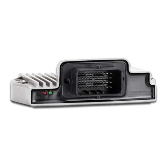
Summary of Contents for Jetter JXM-IO-E32
- Page 1 User Manual JXM-IO-E32 Expansion Module 60885294_00 We automate your success.
- Page 2 Revisions and further development of our products are not automatically mentioned in a reviewed document. Jetter AG shall not be liable for errors in form or content, or for missing updates, as well as for damages or disadvantages resulting from such failure.
-
Page 3: Table Of Contents
Requirements for the installation location .................. 18 6 Electrical connection ........................ 19 Connector specification ...................... 20 6.1.1 Pin assignment ....................... 20 6.1.2 MOLEX mating connector - Specification............... 21 Measures for use in the industrial sector.................. 21 7 Programming............................. 22 Setting the node ID........................ 22 Concept and control ........................ 22 JXM-IO-E32 User Manual... - Page 4 System parameters ........................ 32 NMT commands ......................... 33 Troubleshooting.......................... 33 7.8.1 Heartbeat........................ 34 8 Maintenance and repairs ........................ 35 Maintenance, repairs and disposal..................... 35 Storage and shipment ........................ 35 9 Service ............................... 36 Customer service ........................ 36 10 Spare parts and accessories ...................... 37 JXM-IO-E32 User Manual...
-
Page 5: Introduction
For information on new revisions of this document, visit the download area on our website. This document is not subject to any updating service. Start | Jetter - We automate your success. For further information refer to the following information products: ■... -
Page 6: Safety
Low risk CAUTION Indicates a hazardous situation which, if not avoided, could result in minor or moderate injury. Material damage NOTICE Indicates a situation which, if not avoided, could result in malfunctions or material damage. JXM-IO-E32 User Manual 6 / 38... -
Page 7: Product Description
Product description | 3 3 Product description The JXM-IO-E32 is a CAN device with digital inputs for a wide range of pulse measurements and analog inputs for current, voltage and temperature measure- ment. One pin with supply voltage and ground reference is added to each of the ten analog inputs reducing the cabling effort to a minimum. -
Page 8: Diagnostics Capabilities By Means Of Status Indication
200 ms Measured values are outside their specified ranges. The following errors may have oc- ON: 400 ms curred: Green ■ The PCB temperature is too high. ■ The CPU temperature is too high. OFF: 400 ms JXM-IO-E32 User Manual 8 / 38... -
Page 9: Nameplate
Product description | 3 3.4 Nameplate Fig. 2: Sample nameplate Logo Certification mark Registration number and hardware revision Barcode Serial number Model code number 3.5 Scope of delivery Scope of delivery Item number Quantity JXM-IO-E32-G20-K00 10001912 JXM-IO-E32 User Manual 9 / 38... -
Page 10: Technical Specifications
Jetter AG Technical specifications | 4 4 Technical specifications This chapter contains information on electrical and mechanical data, as well as on operating data of the JXM-IO-E32. 4.1 Dimensions 43.1 38.4 18.6 93.5 Fig. 3: Dimensions in mm 4.2 Mechanical specifications... -
Page 11: Electrical Properties
4.5 EMC values The device has E1 approval according to ECE R10 Rev. 5 and CE conformity ac- cording to ISO 14982. Pulses to ISO Test pulse Values Functional class 7637-2 -450 V +37 V +20 V -150 V +150 V JXM-IO-E32 User Manual 11 / 38... -
Page 12: Inputs
Alternatively, the analog inputs can also be used as digital inputs (DI). The JXM-IO-E32 has 8 separate VEXT_SEN pins and 2 separate VREF_10 pins that should be used to power the sensors. Each sensor supply is output via a PTC thermistor so that a voltage dip caused by a short circuit can be detected. - Page 13 With restrictions, the analog inputs can also be used as PNP inputs. Category Description Digital inputs with frequency measurement Abbreviation Quantity 6 pcs. Pull resistor 5.6 KOhm H level ≥ 4.6 V L level ≤ 1.6 V JXM-IO-E32 User Manual 13 / 38...
-
Page 14: Outputs
Operating current Min. 100 mA Accuracy Diagnostic functions The voltage generated at the 10 V power supply can be read out via SDO. Each channel can be checked for short cir- cuit. Tab. 13: VREF_10V JXM-IO-E32 User Manual 14 / 38... - Page 15 VEXT_SEN is the 24 V output for supplying power to external sensors and is supplied from VBAT_ECU. Abbreviation VEXT_SEN Quantity 8 pcs. Operating voltage VBAT Accuracy Operating current 100 mA Accuracy Diagnostic functions Each channel can be checked for short circuit. Tab. 14: Sensor output VEXT_SEN JXM-IO-E32 User Manual 15 / 38...
-
Page 16: Mechanical Installation
Do not touch the device with the welding electrode or earth clamp. Dirt and moisture can affect the electrical connections. NOTICE ► Plug unused pins with blanking plugs. ► Protect all electrical connections with appropriate single wire seals. JXM-IO-E32 User Manual 16 / 38... -
Page 17: Mounting Orientation
Jetter AG Mechanical installation | 5 5.1 Mounting orientation 5.1.1 Allowed mounting orientations Fig. 4: Allowed mounting orientations JXM-IO-E32 User Manual 17 / 38... -
Page 18: Prohibited Mounting Orientations
The device must be accessible for service work at all times. INFO Overheating due to incorrect mounting orientation If the device switches itself off, check whether the device has overheated due to an unfavorable mounting orientation. JXM-IO-E32 User Manual 18 / 38... -
Page 19: Electrical Connection
► For accurate analog measurements, the sensor supply, sensor signal and sensor ground must be wired together in a star configuration from the device to the sensor. JXM-IO-E32 User Manual 19 / 38... -
Page 20: Connector Specification
OUT_CFG_X VBAT_ECU Power supply for logic unit and sensors VREF_10V_X Stabilized reference voltage for sensors VEXT_SEN_X Battery voltage for sensors Reserved pin that must not be connected! Seal unused n.c. pins with pin plugs. JXM-IO-E32 User Manual 20 / 38... -
Page 21: Molex Mating Connector - Specification
Tab. 16: MOLEX mating connector - Specification 6.2 Measures for use in the industrial sector The JXM-IO-E32 was developed for the automotive sector. In order to be able to use the device also in the industrial sector in conformity with CE, you must imple- ment the following measures: ■... -
Page 22: Programming
7.2 Concept and control The concept of the JXM-IO-E32 is based on the assignment of interfaces to the inputs and out- puts of the device. Each input and output of the device is called a port and can be configured. -
Page 23: Configuration Options Of Connections
AI_PREC_1 … AI_PREC_2 Current input with 16-bit AI_CURRENT resolution (0 … 24 mA) AO_1 … AO_3 20 mA analog output AO_VOLTAGE AO_CURRENT Tab. 17: Supported ports and interfaces - Overview When configuring the outputs, observe the information in chapter Outputs. JXM-IO-E32 User Manual 23 / 38... -
Page 24: Available Interfaces, Parameters, Values And Statuses
4 FI_PNP SENSOR_SUPPLY I_DIGITAL TIMEOUT Frequency TIMEOUT_TIME I_COUNTER SUPPLY_FAULT input GATE_TIME I_FREQUENCY ERROR (active-high I_DUTY_CYCLE INACTIVE with pull-down) I_PERIODIC_TIME I_H_PULSE_TIME I_L_PULSE_TIME 5 DI_NPN SENSOR_SUPPLY I_DIGITAL SUPPLY_FAULT Digital input ERROR (active-low with INACTIVE pull-up) JXM-IO-E32 User Manual 24 / 38... - Page 25 I_FREQUENCY Frequency value, GATE_TIME 0.1 … 10000 and counter value calculated Increment 0.1 I_DIGITAL Digital value Bool 0 or 1 I_COUNTER Count value 0 … 4294967295 I_PERIODIC_TIME Period time in timeout Increment 1 µs JXM-IO-E32 User Manual 25 / 38...
- Page 26 MIN_DEVIATION Minimum deviation for AI input uA, mV or °C values MIN_TEMPERA- If the temperature falls below -45 °C TURE the minimum permitted tem- Increment 1°C perature, the status is set to "TEMPERATUREFAULT". JXM-IO-E32 User Manual 26 / 38...
-
Page 27: Service Data Objects (Sdo)
0x2112 tries IO interface 0 (disabled) type I/O status 1 (disabled bit set) 10 … 29 Input values 30 … 49 Output values W only in Op- erational 50 … 199 Parameter JXM-IO-E32 User Manual 27 / 38... -
Page 28: Device Information
CFG_2 VEXT_SEN_1_SC Bool On/Off VEXT_SEN_2_SC Bool On/Off VEXT_SEN_3_SC Bool On/Off VEXT_SEN_4_SC Bool On/Off VEXT_SEN_5_SC Bool On/Off VEXT_SEN_6_SC Bool On/Off VEXT_SEN_7_SC Bool On/Off VEXT_SEN_8_SC Bool On/Off VREF_10_1_SC Bool On/Off VREF_10_2_SC Bool On/Off Tab. 24: Diagnostic information JXM-IO-E32 User Manual 28 / 38... -
Page 29: Mapping Of Process Data Objects (Pdos)
The transmit PDOs (TPDO 1 ... 4) and receive PDOs (RPDO 1 ... 4) are set using the following parameters. INFO ® More information on the subject CANopen is available in our application- oriented manuals on our homepage. JXM-IO-E32 User Manual 29 / 38... - Page 30 PDOs) Index 0x1801 0x280 + node Index 0x1802 0x380 + node Index 0x1803 0x480 + node Transmission Acyclic type = 0 Type Inhibit Time 0.1 ms Event Time 1 ms Tab. 28: TPDO communication parameters JXM-IO-E32 User Manual 30 / 38...
- Page 31 Type of Default Index Subindex Description Type access value 0x1010 Number of supported entries Saving all parameters When the specific signature 0x65766173 ("save") is written, the pa- rameters are saved. Tab. 32: Save settings in EEPROM JXM-IO-E32 User Manual 31 / 38...
-
Page 32: System Parameters
The vehicle controller reads the CRC via index 0x4556, subindex 1 and saves this value lo- cally remanently. After restarting the JXM-IO-E32, the vehicle controller compares the locally saved CRC value with the value in index 0x4556, subindex 1. If the values do not match, parameteriza- tion must be restarted. -
Page 33: Nmt Commands
Jetter AG Programming | 7 7.7 NMT commands The following NMT commands are supported by JXM-IO-E32: NMT commands Description RESET Node is reset PREOPERATIONAL Switches to Pre-Operational mode OPERATIONAL Switches to Operational mode START Node is started STOP Node is stopped Tab. 35: Supported NMT commands... -
Page 34: Heartbeat
The device sends a heartbeat message cyclically as soon as it is in the Pre-Operational state. Type of Index Subindex Description Type Default value access 0x1017 Producer heartbeat time in ms 1000 Tab. 40: Index of the heartbeat message JXM-IO-E32 User Manual 34 / 38... -
Page 35: Maintenance And Repairs
In case of damaged packaging inspect the device for any visible damage, and in- form your freight forwarder and the Jetter AG of the damage caused during ship- ment. If the device is damaged or has been dropped, it is strictly forbidden to use... -
Page 36: Service
To contact them, please call our technical hotline or use the contact form on our homepage: Technical hotline | Jetter - We automate your success. You are also welcome to send an e-mail to our technical hotline: hotline@jetter.de... -
Page 37: Spare Parts And Accessories
Inadequate accessories might cause damage to the product NOTICE Parts and equipment from other manufacturers might impede the function of the device and cause damage to the product. ► Only use accessories recommended by Jetter AG. JXM-IO-E32 User Manual 37 / 38... - Page 38 Jetter AG Graeterstrasse 2 71642 Ludwigsburg www.jetter.de E-mail info@jetter.de Phone +49 7141 2550-0 We automate your success.
Need help?
Do you have a question about the JXM-IO-E32 and is the answer not in the manual?
Questions and answers