
Related Manuals for Motrec E-290GT


Summary of Contents for Motrec E-290GT
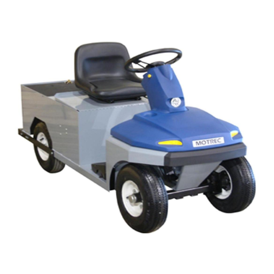
- Page 1 E-290GT OPERATOR AND MAINTENANCE MANUAL SPARE PARTS LISTS INCLUDED SERIAL NUMBER : 1027621 & UP Printed in Canada...
- Page 2 To initiate warranty coverage on any MOTREC vehicle, the Dealer must complete and return the “Sales/Installation Report” to MOTREC within 30 days after delivery to the Original Retail Purchaser; or within 90 days after the delivery date to the Dealer, which ever occurs first. Failure to follow these procedures will result in considering the warranty coverage effective as of the shipment date from the factory.
-
Page 3: Table Of Contents
FORD F-150 DIFFERENTIAL BRAKE CONTROLS STEERING MOTOR AND DRIVE ELECTRICAL DIAGRAM – SEPEX MAIN CIRCUIT ELECTRICAL DIAGRAM – SERIES MAIN CIRCUIT ACCESSORIES – DC/DC CONVERTER DELTA-Q HF CHARGER MOTREC ILLUSTRATED ACCESSORIES CONVERTER INSTALLATION BATTERY DISCHARGE INDICATOR (HOBBS) - 3 -... -
Page 4: Instructions
Instructions INSTRUCTIONS - 4 -... -
Page 5: Safety Warnings For Operators
Instructions SAFETY WARNINGS FOR OPERATORS FAILURE TO OBEY THE FOLLOWING SAFETY RULES MAY RESULT IN SEVERE INJURY. It is the responsibility of the owner of this vehicle to train operators to ensure that they understand the operating characteristics of this vehicle, including training in vehicle stability, and obey the following safety rules and guidelines. -
Page 6: Operating Instructions
Instructions OPERATING INSTRUCTIONS It is the responsibility of the owner of this vehicle to ensure that the operator understands the operating characteristics of this vehicle, and obeys the safety instructions in this manual and ANSI/ITSDF B56.8 & 9 Standards. Do not drive this vehicle unless you are a certified operator as required by OSHA. BEFORE TURNING ON KEYSWITCH Set to neutral, set parking brake, check for visible damage, check brake pedal. -
Page 7: Maintenance
Maintenance MAINTENANCE - 7 -... -
Page 8: Safety Warnings For Service Technicians
Maintenance SAFETY WARNINGS FOR SERVICE TECHNICIANS FAILURE TO OBEY THE FOLLOWING SAFETY RULES MAIN RESULT IN SEVERE INJURY. Owner shall comply with OSHA and ANSI/ITSDF B56.8 & B56.9 Standards for vehicle maintenance. Only qualified and authorized personnel shall be permitted to maintain, repair, adjust and inspect carriers, vehicles, tractors, and batteries. - Page 9 Maintenance Do not try to increase motor speed by changing parameter settings in the speed controller; it can cause accident and severe damage to the motor. SEPEX speed controls are protected by a diode in the power circuit to filter inductive loads in the event of a sudden power interrupt.
-
Page 10: Decals And Labels
Maintenance DECALS AND LABELS ! CAUTION ! The images included in this section depict the decals/markings installed on the vehicle. It is of the utmost importance that theses decals/markings remain unaltered and readable. Else, the sticker or the part baring the marking has to be replaced. Dashboard security warning label: General security warning label: # 5100000002... -
Page 11: Periodic Maintenance Checklist
Maintenance PERIODIC MAINTENANCE CHECKLIST REVISION 080206 ! WARNING ! Maintenance operations must be made by properly trained service technicians. Keep clear from moving parts such as tires, sheaves and motor. Check for all EE protections, when applicable, and keep cables and wires clear from mechanical and rubbing action Batteries contain sulphur acid that can cause severe burns on skin or eyes. -
Page 12: Accelerator
Maintenance ACCELERATOR GEAR Remove the cover. Backlash between gears must be reduced to a minimum by sliding holder; use locktite 262 to lock the three screws. When the plastic gear is fully depressed a small backlash must remain between the gears. When the plastic gear is released its rear portion must not exceed the pedal case. -
Page 13: Belt Installation And Tensioning
Maintenance BELT INSTALLATION AND TENSIONING INSTALLATION Adjust the sprockets using a straight edge. Slide up the edge on the larger pulley until it contacts the smaller pulley. Properly adjusted pulleys will provide three points of contact. Properly aligned pulleys will provide four points of contact. Tighten setscrews and recheck alignment. TENSIONING Check the force F required to provide a deflection of 1/8 in. -
Page 14: Hydraulic & Parking Brakes
Maintenance HYDRAULIC & PARKING BRAKES Revision 2008-02-06 DRUM BRAKES Remove brake drums and check lining wear. Replace shoes and springs if the lining thickness is 1/16" (2mm) or less. Turn the brake adjustment to reduce the clearance between lining and drum. Wheels must turn free when the pedal is released. -
Page 15: Front Axle And Steering
Maintenance FRONT AXLE AND STEERING ! CAUTION ! Before maintenance, turn off all switches, set to neutral, set parking brake, remove the key, and raise the front end of the vehicle supporting it with two jack stands of adequate capacity STEERING INSPECTION Check tire inflation pressure, suspension components, tie rods straightness, tie rod ends play (wear), play (wear) in wheel bearings, kingpins and bushings. -
Page 16: Battery Maintenance
Maintenance BATTERY MAINTENANCE ! WARNING ! It is the responsibility of the owner of this vehicle to ensure that the service technicians are properly trained, read and obey the safety rules and guidelines in this manual (ANSI B56). Maintenance operations must be made by properly trained service technicians only. Before any maintenance work, park the vehicle on a flat level surface, turn off all the switches, set to neutral, remove the key, lift the wheels off the ground and secure with jack stands of adequate capacity. - Page 17 Maintenance BATTERY MOUNTING A loose battery increases damaging effects of vibrations and is more prone to short out. BATTERY DISCHARGE LIMIT Discharging below a 20% state of charge cuts down the battery life and the number of cycles available. At 20% state of charge, specific gravity of 6V battery should be 1180; and 1220 for industrial battery. CHARGING AREA Always charge battery in a well ventilated area set for and approved for charging.
-
Page 18: Battery Charger
Maintenance BATTERY CHARGER ! WARNING ! Always unplug the AC and DC electrical cords before attempting any repairs to the charger. CHARGER DOES NOT TURN ON: Dc cord of portable chargers must be disconnected from batteries after every charge to restart; Check dc fuse links;... -
Page 19: Electrical Troubleshooting
Maintenance ELECTRICAL TROUBLESHOOTING ! WARNING ! Maintenance work must be performed by trained service technicians only. It is the responsibility of the owner of this vehicle to ensure that the services technicians are properly trained, understand and obey the safety rules and guidelines (ANSI B56). All service technicians must read and understand the maintenance warning section in this manual. - Page 20 Maintenance REVERSE ONLY On a SEPEX motor control, check the forward signal input on the controller. On a series wound motor control, a bad forward contactor is the most probable cause of the problem. Switch to forward and check the voltage on the forward control wire. If not B+, replace the F/R switch. If B+, turn off the key switch, disconnect batteries, disconnect power terminals on the F/R contactors, check the resistance across N.C.
- Page 21 Maintenance NO MOTION Make sure that the PMC surface is clean and dry; check the terminal areas. Dust Particles or acid contamination, can create current leaks and cause a PMC malfunction. Check F/R switch Turn on the key switch and set to forward. Check voltage between the forward terminal and the –...
-
Page 22: Curtis Speed Controller
Curtis Speed Controller CURTIS SPEED CONTROLLER - 22 -... - Page 23 Curtis Speed Controller - 23 -...
- Page 24 Curtis Speed Controller - 24 -...
-
Page 25: Wiring : Standard Configuration
Curtis Speed Controller WIRING : STANDARD CONFIGURATION - 25 -... -
Page 26: Diagnostics And Troubleshooting
Curtis Speed Controller DIAGNOSTICS AND TROUBLESHOOTING - 26 -... -
Page 27: Troubleshooting Chart
Curtis Speed Controller TROUBLESHOOTING CHART - 27 -... -
Page 28: Led Diagnostics
Curtis Speed Controller LED DIAGNOSTICS - 28 -... -
Page 29: Programming Parameters - E-280B, E-290, E-360, T-236, T-236D
Curtis Speed Controller PROGRAMMING PARAMETERS – E-280B, E-290, E-360, T-236, T-236D ! WARNING ! The owner of this vehicle shall ensure that the service technicians are qualified, properly trained and obey the safety rules and guidelines in OSHA and ANSI B56 regulations, and in this manual. Before installing and/or programming the PMC, park the vehicle on a flat level surface, lift the wheels off the ground and secure with jack stands of adequate capacity. -
Page 30: Curtis Pmc Motor Controller
Curtis Speed Controller CURTIS PMC MOTOR CONTROLLER - 30 -... - Page 31 Curtis Speed Controller - 31 -...
-
Page 32: Overview
Curtis Speed Controller OVERVIEW - 32 -... - Page 33 Curtis Speed Controller - 33 -...
- Page 34 Curtis Speed Controller - 34 -...
-
Page 35: Wiring : Standard Configuration
Curtis Speed Controller WIRING : STANDARD CONFIGURATION - 35 -... - Page 36 Curtis Speed Controller - 36 -...
- Page 37 Curtis Speed Controller - 37 -...
- Page 38 Curtis Speed Controller - 38 -...
-
Page 39: Maintenance And Adjustment
Curtis Speed Controller MAINTENANCE AND ADJUSTMENT - 39 -... - Page 40 Curtis Speed Controller - 40 -...
- Page 41 Curtis Speed Controller - 41 -...
-
Page 42: Spare Parts
Spare Parts SPARE PARTS - 42 -... -
Page 43: Body
Spare Parts BODY REF. PART NO DESCRIPTION 6107290001 BODY 2500008 CABLE PROTECTOR 280003 CARGO DECK 2500250001 DASH BOARD 1005003 BUCKET SEAT 2801008 REAR BUMPER WITH PLATE 280105 283001 4.80 X 8 PNEUMATIC WHEEL, 5 BOLT 283002 4.80 X 8 FOAMFILLED WHEEL, 5 BOLT 16”... -
Page 44: Front Light Support
Spare Parts FRONT LIGHT SUPPORT - 44 -... -
Page 45: Ford F-150 Differential
Spare Parts FORD F-150 DIFFERENTIAL - 45 -... - Page 46 Spare Parts - 46 -...
-
Page 47: Brake Controls
Spare Parts BRAKE CONTROLS PART NO DESCRIPTION REF PART NO DESCRIPTION 242801 Rubber 3616013 8 in. Handbrake lever 242816 Spring 362831 Cable 2416006 Lever 362832 Clip 242831 Pivot 362833 Cable stop 242817 Lubrication fitting 3616014 Handbrake band (cable side) Clevis pin 3/8 x 1 3616012 Handbrake band 122813... -
Page 48: Steering
Spare Parts STEERING - 48 -... - Page 49 Spare Parts REF. PART NO DESCRIPTION 2104250001 UNIVERSAL JOINT 2806240001 PROTECTOR 481451 STEERING 2208250001 BUSHING 2530001 FLANGE BLOC 3/4 2200250001 STEERING SHAFT 481467 GEAR BOX 3030004 SPACER 2530009 PITMAN ARM 2530007 FRONT TIE ROD 2530005 LEFT AXLE 2530006 RIGHT AXLE 241002 OIL SEAL 241003...
-
Page 50: Motor And Drive
Spare Parts MOTOR AND DRIVE COMMON PARTS DESCRIPTION PART # DESCRIPTION PART # 1 PULLEY 262424 8 MOTOR BASE, FORD Contact manuf. 2 V BELT 242431 BELT TENSIONER 2152002 3 PULLEY 3651001 9 SEAL 484001 4 BELT, EAGLE 3651002 10 BEARING 484003 5 MOTOR BASE, GM Contact manuf. -
Page 51: Electrical Diagram - Sepex Main Circuit
Spare Parts ELECTRICAL DIAGRAM – SEPEX MAIN CIRCUIT DIAGRAMME ÉLECTRIQUE – CIRCUIT PRINCIPAL SEPEX - 51 -... -
Page 52: Electrical Diagram - Series Main Circuit
Spare Parts ELECTRICAL DIAGRAM – SERIES MAIN CIRCUIT DIAGRAMME ÉLECTRIQUE – CIRCUIT PRINCIPAL SÉRIES - 52 -... -
Page 53: Accessories - Dc/Dc Converter
Spare Parts ACCESSORIES – DC/DC CONVERTER ACCESSOIRES – CONVERTISSEUR DC/DC - 53 -... - Page 54 EMERGENCY PUSH BUTTON 3109800001 EMERGENCY PUSH BUTTON LABEL 3109800006 DC-DC CONVERTER HOUR METER CONNECTOR SPEED CONTROL CONNECTOR BATTERY CHARGER CONNECTOR MAIN CONTACTOR 486222 Y2.A,B F/R CONTACTOR 486217 F/R BUSSBARS 2469003 STATIC STRAP 2450001 * Consult Motrec Illustrated parts - 54 -...
-
Page 55: Delta-Q Hf Charger
Spare Parts DELTA-Q HF CHARGER PART NO DESCRIPTION 3102240002 24V CHARGER ( U.S. BATTERY ) 3102240003 24V CHARGER ( LIFELINE BATTERY ) 3102240004 24V CHARGER ( GEL 180AH BATTERY) 3102240005 24V CHARGER ( 27TM BATTERY ) 36V CHARGER ( U.S. BATTERY ) 3102302001 3102302002 36V CHARGER ( LIFELINE BATTERY ) - Page 56 Spare Parts - 56 -...
- Page 57 Spare Parts - 57 -...
-
Page 58: Motrec Illustrated Accessories
Spare Parts MOTREC ILLUSTRATED ACCESSORIES Headlight Red Tail/Brake light Left: 3111480003 Strobelight, polemount Housing: 3069012R Horn button VIP Right: 3111480004 Amber 12-80V: 3116000001 Bulb 12V: 3117240001 2208224002 Bulb H/L: 3117480001 Red 12-80V: 2469001 Bulb Turn: 3117480003 Blue 12-80V: 3690008 Bulb Mark:... - Page 59 Spare Parts Wiper motor Cab heater 12V: 3113000001 12V: 3103300001 24V: 486211 Analog Voltmeter Headlamp 12V: 3111250007 36V: 3669008 12V : 3069007 48V: 4869020 24V : 2469002 36-48V : 3669002 Wiper arm 2800000001 Headlamp 12V Dome light 3669006 12V: 3111300001 Bulb 12V: 3111300002 HOBBS Gauge...
-
Page 60: Converter Installation
Spare Parts CONVERTER INSTALLATION - 60 -... -
Page 61: Battery Discharge Indicator (Hobbs)
Spare Parts BATTERY DISCHARGE INDICATOR (HOBBS) This indicator monitors : the residual capacity of batteries; operating hours; status of service down counter. The residual capacity of the battery is monitored via an 8-LED bar display. When the left red LED lights, the batteries must be charged to avoid damage.
Need help?
Do you have a question about the E-290GT and is the answer not in the manual?
Questions and answers