
Related Manuals for Motrec T-224


Summary of Contents for Motrec T-224
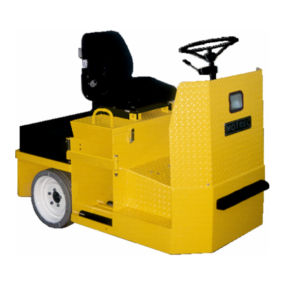
- Page 1 T-224 OPERATOR AND MAINTENANCE MANUAL SPARE PARTS LISTS INCLUDED SERIAL NUMBER : 1028579 & UP Printed in Canada...
- Page 2 To initiate warranty coverage on any MOTREC vehicle, the Dealer must complete and return the “Sales/Installation Report” to MOTREC within 30 days after delivery to the Original Retail Purchaser; or within 90 days after the delivery date to the Dealer, which ever occurs first. Failure to follow these procedures will result in considering the warranty coverage effective as of the shipment date from the factory.
-
Page 3: Table Of Contents
BATTERY MAINTENANCE ELECTRICAL TROUBLESHOOTING CURTIS SPEED CONTROLLER WIRING : STANDARD CONFIGURATION DIAGNOSTICS AND TROUBLESHOOTING TROUBLESHOOTING CHART LED DIAGNOSTICS PROGRAMMING PARAMETERS –T-224/224D SPARE PARTS BODY FORD F-150 DIFFERENTIAL DIFFERENTIAL BRAKE CONTROLS, DEADMAN SEAT BRAKE STEERING WHEEL AND FRONT AXLE TILT/TEL STEERING WHEEL AND FRONT AXLE MOTOR AND DRIVE ELECTRICAL DIAGRAM –... -
Page 4: Instructions
Instructions INSTRUCTIONS - 4 -... -
Page 5: Safety Warnings For Operators
Instructions SAFETY WARNINGS FOR OPERATORS • FAILURE TO OBEY THE FOLLOWING SAFETY RULES MAIN RESULT IN SEVERE INJURY. • It is the responsibility of the owner of this vehicle to train operators to ensure that they understand the operating characteristics of this vehicle, including training in vehicle stability, and obey the following safety rules and guidelines. -
Page 6: Maintenance
Maintenance MAINTENANCE - 6 -... -
Page 7: Safety Warnings For Service Technicians
Maintenance SAFETY WARNINGS FOR SERVICE TECHNICIANS FAILURE TO OBEY THE FOLLOWING SAFETY RULES MAIN RESULT IN SEVERE INJURY. Owner shall comply with OSHA and ASME/ANSI B56.8 & B56.9 regulations for vehicle maintenance. Only qualified and authorized personnel shall be permitted to maintain, repair, adjust and inspect carriers, vehicles, tractors, and batteries. - Page 8 Maintenance Do not try to increase motor speed by changing parameter settings in the speed controller; it can cause accident and severe damage to the motor. SEPEX speed controls are protected by a diode in the power circuit to filter inductive loads in the event of a sudden power interrupt.
-
Page 9: Decals And Labels
Maintenance DECALS AND LABELS ! CAUTION ! The images included in this section depict the decals/markings installed on the vehicle. It is of the utmost importance that theses decals/markings remain unaltered and readable. Else, the sticker or the part baring the marking has to be replaced. Dashboard security warning label: General security warning label: Respectively, key switch markings, forward/reverse selector markings and light switch marking:... -
Page 10: Periodic Maintenance Checklist
Maintenance PERIODIC MAINTENANCE CHECKLIST ! WARNING ! Maintenance operations must be made by properly trained service technicians. − Keep clear from moving parts such as tires, sheaves and motor. − Check for all EE protections, when applicable, and keep cables and wires clear from mechanical and rubbing action −... -
Page 11: Accelerator
Maintenance ACCELERATOR GEAR − Remove the cover. − Backlash between gears must be reduced to a minimum by sliding holder; use locktite 262 to lock the three screws. − When the plastic gear is fully depressed a small backlash must remain between the gears. −... -
Page 12: Belt Installation And Tensioning
Maintenance BELT INSTALLATION AND TENSIONING INSTALLATION Adjust the sprockets using a straight edge. Slide up the edge on the larger pulley until it contacts the smaller pulley. Properly adjusted pulleys will provide three points of contact. Properly aligned pulleys will provide four points of contact. Tighten setscrews and recheck alignment. TENSIONING Check the force F required to provide a deflection of 1/8 in. -
Page 13: Hydraulic Brakes
Maintenance HYDRAULIC BRAKES DRUM BRAKES Remove brake drums and check linings wear; the linings should have a thickness exceeding 1/16" (1.5 mm). Turn the brake adjustment to reduce the clearance between lining and drum but avoid contact or drag when the wheels are turned and the pedal is released. DISC BRAKES Check pad linings for excessive wear;... -
Page 14: Deadman Seat Brake
Maintenance DEADMAN SEAT BRAKE Maintenance work must be performed by trained personnel only. Before any maintenance work, turn key switch to off and disconnect battery terminal. LUBRICATION: Grease the spherical rod end, two pillow blocks and brake cable arm. CHECK BRAKE PAD: Minimum brake pad wear is 1/8 inch ( 3 mm ). -
Page 15: Battery Maintenance
Maintenance BATTERY MAINTENANCE ! WARNING ! − It is the responsibility of the owner of this vehicle to ensure that the service technicians are properly trained, read and obey the safety rules and guidelines in this manual (ANSI B56). − Maintenance operations must be made by properly trained service technicians only. −... - Page 16 Maintenance BATTERY MOUNTING A loose battery increases damaging effects of vibrations and is more prone to short out. BATTERY DISCHARGE LIMIT Discharging below a 20% state of charge cuts down the battery life and the number of cycles available. At 20% state of charge, specific gravity of 6V battery should be 1180; and 1220 for industrial battery. CHARGING AREA −...
-
Page 17: Electrical Troubleshooting
Maintenance ELECTRICAL TROUBLESHOOTING ! WARNING ! Maintenance work must be performed by trained service technicians only. It is the responsibility of the owner of this vehicle to ensure that the services technicians are properly trained, understand and obey the safety rules and guidelines (ANSI B56). All service technicians must read and understand the maintenance warning section in this manual. - Page 18 Maintenance REVERSE ONLY On a SEPEX motor control, check the forward signal input on the controller. On a series wound motor control, a bad forward contactor is the most probable cause of the problem. Switch to forward and check the voltage on the forward control wire. If not B+, replace the F/R switch. If B+, turn off the key switch, disconnect batteries, disconnect power terminals on the F/R contactors, check the resistance across N.C.
- Page 19 Maintenance NO MOTION Make sure that the PMC surface is clean and dry; check the terminal areas. Dust Particles or acid contamination, can create current leaks and cause a PMC malfunction. Check F/R switch Turn on the key switch and set to forward. Check voltage between the forward terminal and the –...
-
Page 20: Curtis Speed Controller
Curtis Speed Controller CURTIS SPEED CONTROLLER - 20 -... - Page 21 MANUAL 12 4 4 MultiMode™ MOTOR CONTROLLER © 2001 CURTIS INSTRUMENTS, INC. DESIGN OF CURTIS PMC 1200 SERIES CONTROLLERS PROTECTED BY U.S. PATENT NO. 4626750. CURTIS PMC 235 East Airway Boulevard 1244 Manual, p/n 16958 Livermore, California 94568 USA Rev. B: January 2001 Tel: 925-961-1088 Fax: 925-961-1099 www.curtisinst.com...
- Page 22 1244 Manual p/n 16958, Rev. B: January 2001 © 2001 CURTIS INSTRUMENTS, INC. CURTIS INSTRUMENTS, INC. 200 KISCO AVENUE MOUNT KISCO, NEW YORK 10549 USA 914-666-2971 914-666-2188 CURTIS PMC 235 EAST AIRWAY BOULEVARD LIVERMORE, CALIFORNIA 94550 USA 925-961-1088 925-961-1099 ADDITIONAL OFFICES located in Bulgaria, China, England, France, Germany, India, Italy, Japan, Netherlands, Puerto Rico, Russia, Sweden, and Switzerland...
-
Page 23: Wiring: Standard Configuration
2 — INSTALLATION & WIRING: Controller WIRING: Standard Configuration Figure 3 shows the typical wiring configuration for most applications. The interlock switch is typically a seat switch, tiller switch, or foot switch. Standard Power Wiring Motor armature winding is straightforward, with the armature’s A1 connection going to the controller’s B+ bus bar and the armature’s A2 connection going to the controller’s M- bus bar. -
Page 24: Diagnostics And Troubleshooting
8 — DIAGNOSTICS & TROUBLESHOOTING DIAGNOSTICS AND TROUBLESHOOTING The 1244 controller provides diagnostics information to assist technicians in troubleshooting drive system problems. The diagnostics information can be obtained by observing the appropriate display on the handheld programmer, the fault codes issued by the Status LED, or the fault display driven by the controller’s Fault 1 and Fault 2 outputs. -
Page 25: Troubleshooting Chart
8— DIAGNOSTICS & TROUBLESHOOTING TROUBLESHOOTING CHART Table 5 PROGRAMMER FAULT EXPLANATION POSSIBLE CAUSE CODE LCD DISPLAY CATEGORY self-test or watchdog fault 1. Controller defective. HW FA I L SA FE 1 - 2 - 3 internal M- short to B- 1. -
Page 26: Led Diagnostics
8 — DIAGNOSTICS & TROUBLESHOOTING LED DIAGNOSTICS A Status LED is built into the 1244 controller. It is visible through a window in the label on top of the controller. This Status LED displays fault codes when there is a problem with the controller or with the inputs to the controller. During normal operation, with no faults present, the Status LED flashes steadily on and off. -
Page 27: Programming Parameters -T-224/224D
Curtis Speed Controller PROGRAMMING PARAMETERS –T-224/224D ! WARNING ! The owner of this vehicle shall ensure that the service technicians are qualified, properly trained and obey the safety rules and guidelines in OSHA and ANSI B56 regulations, and in this manual. -
Page 28: Spare Parts
Spare Parts SPARE PARTS - 28 -... -
Page 29: Body
Spare Parts BODY REF. PART NO DESCRIPTION 2300044 REAR COVER 2205001 GS-12 GRAMMER SEAT 2205002 GS-12 GRAMMER SEAT (SWITCH) 2305002 DELUXE GRAMMER SEAT 2807001 5-BOLT, SOLID BLACK RUBBER WHEEL 2207004 5-BOLT, 16” O.D. N.M. MOLD-ON WHEEL 2200018 ROLLER 2200019 SHAFT 2200010 BEARING 2205003... -
Page 30: Ford F-150 Differential
Spare Parts FORD F-150 DIFFERENTIAL - 30 -... - Page 31 Spare Parts - 31 -...
-
Page 32: Differential
Spare Parts DIFFERENTIAL - 32 -... - Page 33 Spare Parts REF. PART NO DESCRIPTION 481433 DISC (HYDRAULIC BRAKE) 2173236001 REAR AXLE 242053 LOCK 242054 WHEEL STUD 481430K LEFT CALIPER 481431K RIGHT CALIPER 481430RK REPAIRE KIT, CALIPER 2420011 OIL SEAL 2420010 NEEDLE BEARING 242058 242059 FLAT WASHER 2113000002 PULLEY W90 2122236001 MOUNTING PLATE (CALIPER) 242060 OIL SEAL...
-
Page 34: Brake Controls, Deadman Seat Brake
Spare Parts BRAKE CONTROLS, DEADMAN SEAT BRAKE PART NO DESCRIPTION REF PART NO DESCRIPTION 242800 RUBBER PEDAL 367002 MICRO-SWITCH 242816 SPRING 2216017 BRASS BUSHING 2316008 LEVER 2216009 CABLE PULL BRACKET 202811 PIVOT 2316012 TUBE-HOLDER 242817 LUBRICATION FITTING 2316013 ADJUSTMENT ROD CLEVIS PIN 3/8 X 1 2290002 ROD END 1/2"... -
Page 35: Steering Wheel And Front Axle
Spare Parts STEERING WHEEL AND FRONT AXLE PART NO DESCRIPTION REF PART NO DESCRIPTION 481451 STEERING WHEEL 201434 WASHER BOLT 3/8-NC X 3/4 2235001 SHAFT LOCKWASHER 3/8 2235003 OIL SEAT 481454 2235004 TAPER BEARING 231401 FORK 2235002 201423 BALL BEARING 241005 WHEEL NUT BOLT 1/2-NF X 1 1/2... -
Page 36: Tilt/Tel Steering Wheel And Front Axle
Spare Parts TILT/TEL STEERING WHEEL AND FRONT AXLE PART NO DESCRIPTION REF PART NO DESCRIPTION 2330013 STEERING WHEEL 2230014-RB RIGHT BRACKET BOLT 3/8-NC X 3/4 2230014-MBK HORN BRUSH KIT LOCKWASHER 3/8 2235001 SHAFT 481454 2235003 OIL SEAT 231401 FORK 2235004 TAPER BEARING 201423 BALL BEARING... -
Page 37: Motor And Drive
Spare Parts MOTOR AND DRIVE COMMON PARTS DESCRIPTION PART # DESCRIPTION PART # 1 PULLEY 262424 8 MOTOR BASE, FORD Contact manuf. 2 V BELT 242431 BELT TENSIONER 2152002 3 PULLEY 3651001 9 SEAL 484001 4 BELT, EAGLE 3651002 10 BEARING 484003 5 MOTOR BASE, GM Contact manuf. -
Page 38: Electrical Diagram - Sepex Main Circuit
Spare Parts ELECTRICAL DIAGRAM – SEPEX MAIN CIRCUIT DIAGRAMME ÉLECTRIQUE – CIRCUIT PRINCIPAL SEPEX - 38 -... -
Page 39: Accessories - No Dc/Dc Onverter
Spare Parts ACCESSORIES – NO DC/DC ONVERTER ACCESSOIRES – SANS CONVERTISSEUR DC/DC - 39 -... - Page 40 HYDRAULIC BRAKE LIGHT SWITCH 3669004 EMERGENCY PUSH BUTTON 3109800001 EMERGENCY PUSH BUTTON, LABEL 3109800006 HOUR METER CONNECTOR SPEED CONTROL CONNECTOR MAIN CONTACTOR – 24V 246112 GE MAIN CONTACTOR – 24V GE800AH205XO STATIC STRAP 2450001 * Consult Motrec illustrated parts - 40 -...
-
Page 41: Motrec Illustrated Accessories
Spare Parts MOTREC ILLUSTRATED ACCESSORIES Headlight Red Tail/Brake light Left: 3111480003 Strobelight, polemount Housing: 3069012R Horn button VIP Right: 3111480004 Amber 12-80V: 3116000001 Bulb 12V: 3117240001 2330014 Bulb H/L: 3117480001 Red 12-80V: 2469001 Bulb Turn: 3117480003 Blue 12-80V: 3690008 Bulb Mark:... - Page 42 Spare Parts Wiper arm 2800000001 Cab heater DC-DC converter, 10A 12V: 3103300001 12-48V: 3069019 Headlamp 12V: 3111250002 36V: 3669008 48V: 4869020 Wiper blade 14” Blade: 2800000002 DC-DC Converter, 25A 18” Blade: 2800000003 12-48V: 3124000002 72-80V: 3124880001 Headlamp 12V Dome light 3669006 12V: 3111300001...
-
Page 43: Converter Installation
Spare Parts CONVERTER INSTALLATION - 43 -... -
Page 44: Battery Discharge Indicator (Hobbs)
Spare Parts BATTERY DISCHARGE INDICATOR (HOBBS) This indicator monitors : − the residual capacity of batteries; − operating hours; − status of service down counter. The residual capacity of the battery is monitored via an 8-LED bar display. When the left red LED lights, the batteries must be charged to avoid damage. -
Page 45: Addendum
Addendum ADDENDUM - 45 -... -
Page 46: Curtis Foot Pedal
Addendum CURTIS FOOT PEDAL PART. NO DESCRIPTION 3062001C ACCELERATOR CURTIS 367008 POTENTIOMETER 2262004C SPRING 2262001C MICRO-SWITCH 2262003C LEVER 3662002 CABLE PROTECTOR T-224/236/248 CLAUDE L RESP : MODEL(E) : 235A224001 NO : SER : TO/À : - 46 -...
Need help?
Do you have a question about the T-224 and is the answer not in the manual?
Questions and answers