Advertisement
Quick Links
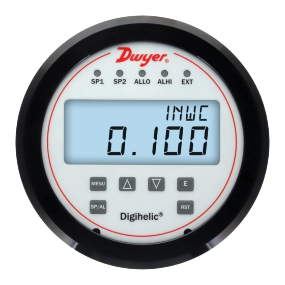
The Series DHC Digihelic
®
possessing a digital display gage, control relay switches, and a transmitter with both
current and voltage outputs. Combining these 3 features allows the reduction of
several instruments with one product, saving inventory, installation time, and cost.
The Series DHC Digihelic
®
pressure, velocity, and volumetric flow applications reading in several commonly
used engineering units with optional unidirectional or bidirectional ranges. These
units achieve a 1.5% or better accuracy on extremely low ranges, and 0.5% accuracy
for ranges at or above 1 in w.c. Calibration can be performed in the field, making
maintaining its accuracy more manageble. Additionally, the Series DHC Digihelic
differential pressure controller includes 2 SPDT control relays with adjustable
deadbands. Programming the unit is simple using the built-in menu. With scalable
4-20 mA, selectable voltage process outputs, and selectable Modbus
communication, this controller can easily fit into your application.
INSTALLATION
Select a clean, dry location that is free from shock and vibration where temperature
limits will not be exceeded. Distance from the transmitter to the receiver is limited
only by total loop resistance. See WIRING section. The tubing feeding pressure to
the instrument can be practically any length required, but longer lengths will slightly
increase response time.
All standard models are calibrated for use in a vertical mounting position. The DHC
will perform properly when mounted at any angle but should be zeroed before use.
Pressure Connections
For installation convenience, there are two sets of 1/8˝ female NPT pressure ports;
one set is located on the back of the unit and the other is located on the side. Be sure
to seal the unused ports with the included pipe plugs (accessory A-330).
• Positive Pressure: Connect tubing to the HIGH PRESSURE port (indicated with a
"+" sign) and vent the LOW PRESSURE port (indicated with a "-" sign) to
atmosphere.
• Negative (Vacuum) Pressure: Connect tubing to the LOW PRESSURE port
(indicated with a "-" sign) and vent the HIGH PRESSURE port (indicated with a
"+" sign) to atmosphere. When operating this device in a dusty environment, install
an optional A-331 filter vent plug into the vented port to keep interior clean.
• Differential Pressure: Connect tubing from the higher source to the HIGH
PRESSURE port (indicated with a "+" sign) and from the lower source to the LOW
PRESSURE port (indicated with a "-" sign).
DWYER INSTRUMENTS, INC.
P.O. BOX 373 • MICHIGAN CITY, INDIANA 46360, U.S.A.
1.800.544.2843
Series DHC Digihelic
Specifications - Installation and Operating Instructions
53/64
[20.96]
1-3/8
[34.93]
Differential Pressure Controller is a 3-in-1 instrument
differential pressure controller is the ideal instrument for
www.calcert.com
15
10
20
5
25
0
30
Differential Pressure Controller
®
1/8 FEMALE NPT HIGH
PRESSURE CONNECTION
1 [25.40]
1/8 FEMALE NPT LOW
PRESSURE CONNECTION
3x Ø3/16 [4.77] HOLES EQUALLY
SPACED ON A 4-1/8 [104.78] B.C.
SURFACE MOUNTING
1/2 [12.70]
SPECIFICATIONS
Service: Air and non-combustible, compatible gases.
Wetted Materials: Consult factory.
Housing Material: Polycarbonate.
Accuracy: ±0.5% FSO for all ranges, except 0.5 in w.c. @ ±1% FSO, and ranges at
or below ±0.25 in w.c. @ ±1.5% FSO.
Stability: < ±1% / year FSO.
Pressure Limits: Ranges > 1 in w.c.: 6 psi max operation, 6 psi burst; Ranges ≤ 1
in w.c.: 3.6 psi max operation, 6 psi burst.
®
Temperature Limits: -4 to 158°F (-20 to 70°C).
Thermal Effects: .02% FS / °F (.036% FS / °C).
Power Requirements: 12-28 VDC or 12-28 VAC 50 to 400 Hz.
or BACnet
®
Power Consumption: 3 VA max.
Output Signal: 4-20 mA (4-wire); 0-10 V, 0-5 V, 1-5 V, and 2-10 V (4-wire).
Communication: BACnet MS/TP or Modbus
Supported Baud Rate: 9600, 19200, 38400, 57600, 76800, 115200.
Device Load: 1/8 unit load.
Zero and Span Adjustments: Accessible via menus.
Response Time: 400 ms (damping set to 0).
Display: Backlit LCD display, LED setpoint indicators.
Electrical Connections: 15 pin male high density D-sub connection. 18˝ (46 cm)
cable with 15 conductors included.
Process Connections: 1/8˝ female NPT ports on side and back.
Enclosure Rating: NEMA 4X (IP66).
Mounting Orientation: Not position sensitive.
Size: 5˝ OD (127 mm) x 1.9˝ (48 mm) deep.
Weight: 8.8 oz (250 g).
Compliance: BTL, CE.
SWITCH SPECIFICATIONS
Switch Type: 2 SPDT relays.
Electrical Rating: 1 A @ 30 VAC/VDC.
Set Point Adjustment: Accessible via menus.
MODEL CHART
Model
Range
DHC-002
0.25 in w.c.
DHC-003
0.5 in w.c.
DHC-004
1 in w.c.
DHC-006
2.5 in w.c.
DHC-008
5 in w.c.
DHC-009
10 in w.c.
DHC-010
25 in w.c.
DHC-011
50 in w.c.
DHC-012
100 in w.c.
DHC-202
±0.25 in w.c.
DHC-203
±0.5 in w.c.
DHC-204
±1 in w.c.
DHC-206
±2.5 in w.c.
Phone: 219-879-8000
Fax: 219-872-9057
HIGH
PRESSURE
PORT
1 [25.40]
LOW
PRESSURE
PORT
15/64
1/2 [12.70]
[5.84]
1-43/64
[42.34]
®
RTU.
Model
Range
DHC-208
±5 in w.c.
DHC-209
±10 in w.c.
DHC-053
60 Pa
DHC-055
125 Pa
DHC-056
250 Pa
DHC-253
±60 Pa
DHC-255
±125 Pa
DHC-256
±250 Pa
DHC-082
6 mm w.c.
DHC-084
25 mm w.c.
DHC-282
±6 mm w.c.
DHC-284
±25 mm w.c.
www.dwyer-inst.com
e-mail: info@dwyermail.com
sales@calcert.com
Bulletin P-DHC
Ø5 [127.00]
Advertisement

Related Manuals for Dwyer Instruments Digihelic DHC Series


Summary of Contents for Dwyer Instruments Digihelic DHC Series
- Page 1 ±0.5 in w.c. DHC-282 ±6 mm w.c. DHC-204 DHC-284 ±1 in w.c. ±25 mm w.c. DHC-206 ±2.5 in w.c. DWYER INSTRUMENTS, INC. Phone: 219-879-8000 www.dwyer-inst.com P.O. BOX 373 • MICHIGAN CITY, INDIANA 46360, U.S.A. Fax: 219-872-9057 e-mail: info@dwyermail.com 1.800.544.2843 www.calcert.com sales@calcert.com...
- Page 2 MOUNTING Surface Mounting The DHC may be either panel (flush) mounted or surface mounted. 1. Use the drill template (Figure 4 on the next page) on the front of the desired mounting surface. Provide three 3/16˝ diameter holes in panel on a 4-1/8˝ Panel Mounting Including -SS Bezel: diameter bolt circle.
- Page 3 Figure 4: Surface mounting drill template 1.800.544.2843 www.calcert.com sales@calcert.com...
- Page 4 1.800.544.2843 www.calcert.com sales@calcert.com...
- Page 5 WIRING FRONT PANEL SP2 DESCRIPTOR ALARM DESCRIPTOR The DHC uses a standard 15 pin male high density D-Sub connector available from most electronic distributors. A pre-wired 18˝ cable is included with each unit. See SP1 DESCRIPTOR below table for cable color wiring information. EXTERNAL INPUT 15 Pin Connector Function...
- Page 6 MAIN MENUS AND SUBMENUS Unit (Velocity) SUB MENU For velocity measurement, the following units are available: Main Menu Selections (Upper Right Display Reads MENU) • SFPM - Standard feet per minute • Pin - Set a custom pin code to lock out access to all menu settings •...
- Page 7 uoUt (Voltage Output Range) SUB MENU rLy1, rLy2 (Relay 1 Source, Relay 2 Source) SUB MENUS The voltage output range setting allows the voltage output limits to be configured to 1 • OFF - Relay not used of 4 common ranges. Available options include: 0-10 V, 0-5 V, 1-5 V, and 2-10 V. The •...
- Page 8 Conn (Connection) MAIN MENU SPAN (Span Calibration) SUB MENU The Conn menu contains SUB MENUS to configure the RS-485 serial parameters and For an accurate calibration, perform a Zero calibration first. The pressure to apply selected protocol. The SUB MENUS are: will depend on the selected mode and the POH, VOH or FOH value.
- Page 9 AUTO SERIAL CONFIGURATION BACnet Communication Protocol Objects Overview Auto serial configuration enables the device to determine the baud rate, parity and The instrument supports the following objects: stop bits directly from the serial traffic. This allows a device to be quickly and easily SUPPORTED BACNET COMMUNICATION PROTOCOL OBJECTS deployed after a valid RS-485 MAC address is chosen.
- Page 10 BACnet Communication Protocol Objects Analog Value - Velocity Device Object This object represents the current velocity reading in the selected unit measure. The velocity unit is set via the units property and is independent of the display unit. Property Default Value Property Data Type Access Object Identifier...
- Page 11 Analog Value - Valley Multi-State Value - Process Mode This object represents the minimum process value measured since the last power This object represents the process or operating mode of the instrument. This setting cycle or reset. The unit of measure matches the selected process value. This value determines which process variable is output on the analog channels and measurement cannot be reset remotely.
- Page 12 Multi-State Value - Voltage Output Range Analog Value - Set Point 1 Reset Value This object represents the nominal range of the voltage output channel. This object represents the process value at which set point 1 transitions from active to inactive.
- Page 13 Analog Value - Set Point 2 Reset Value Binary Value - Alarm High Limit Status This object represents the process value at which set point 2 transitions from active to This object represents the current status of the alarm high limit. When active, the ALHI inactive.
- Page 14 Binary Value - Alarm Low Limit Status Multi-State Value - Relay 1 Source This object represents the current status of the alarm low limit. When active, the ALLO This object represents the relay 1 source setting. The selected source determines LED on the instrument face is illuminated.
- Page 15 Multi-State Value - Relay 2 Action Binary Value - External Input Status This object represents the relay 2 action setting. The selected action determines what This object represents the current status of the external input. When active, the EXT happens when the relay is active. If the selected source is an alarm, then the state text LED on the instrument face is illuminated.
-
Page 16: Input Registers
Modbus Communications Protocol Overview Holding Registers ® Modbus communications protocol installations should comply with INPUT REGISTERS NOTICE ® Modbus Communication Protocol over Serial Line Specification ® Register Description Data Type Range and Implementation Guide V1.02, Modbus Organization, Inc., 2006 ® 0001-0016 Device Name String(32) -
Page 17: Maintenance
Multi-Address Support MAINTENANCE Multi-address support allows a register to be read or written to using different byte Upon final installation of the Series DHC, no routine maintenance is required. The orientations specified by the address range. For example, input register 0001 can also Series DHC is not field serviceable and should be returned if repair is needed. - Page 18 MENU MAPS POWER ON [RESET] MENU LEGEND PRESS MENU BUTTON PRESS ENTER BUTTON PRESS AND HOLD ENTER BUTTON DISPLAY ALL SEGMENTS PRESS SPAL BUTTON PRESS UP BUTTON PRESS DOWN BUTTON PRESS RST BUTTON FIRMWARE VERSION MODEL NUMBER MODEL PRESSURE RANGE HOME SCREEN MODE = PRESSURE CORRECT...
- Page 19 MAIN MENU CONFIGURE PIN [0000 = DISABLED] DISCARD SAVE CHANGE DIGIT NEXT DIGIT [MOVE CARON] OPERATION MENU SET POINT MENU ALARM MENU HOME SCREEN RELAY MENU EXTERNAL INPUT MENU DISPLAY MENU CONNECTION MENU CALIBRATION MENU 1.800.544.2843 www.calcert.com sales@calcert.com...
- Page 20 OPERATION MENU OPERATION MODE MEASUREMENT UNIT MAIN MENU OPERATION MENU [CONTINUED] 1.800.544.2843 www.calcert.com sales@calcert.com...
- Page 21 OPERATION MENU [CONTINUED] DISCARD PRESSURE SAVE OUTPUT LOW AVAILABLE WHEN CHANGE DIGIT MODE = PRESSURE NEXT DIGIT [MOVE CARON] PRESSURE OUTPUT HIGH AVAILABLE WHEN VELOCITY MODE = VELOCITY K-FACTOR OR FLOW DISCARD VELOCITY SAVE OUTPUT LOW AVAILABLE WHEN CHANGE DIGIT MODE = VELOCITY NEXT DIGIT (MOVE CARON) VELOCITY...
- Page 22 OPERATION MENU [CONTINUED] VOLTAGE OUTPUT RANGE 1.800.544.2843 www.calcert.com sales@calcert.com...
- Page 23 SET POINT MENU SET POINT 1 ENABLE SET POINT 2 ENABLE MAIN MENU 1.800.544.2843 www.calcert.com sales@calcert.com...
- Page 24 ALARM MENU ALARM HIGH LIMIT ENABLE ALARM LOW LIMIT ENABLE MAIN MENU ALARM RESET TYPE ALARM INHIBIT ENABLE DISCARD ALARM DELAY SAVE CHANGE DIGIT NEXT DIGIT [MOVE CARON] 1.800.544.2843 www.calcert.com sales@calcert.com...
- Page 25 RELAY MENU RELAY 1 SOURCE MAIN MENU RELAY 2 SOURCE RELAY MENU [CONTINUED] 1.800.544.2843 www.calcert.com sales@calcert.com...
- Page 26 RELAY MENU [CONTINUED] RELAY 1 ACTION IF RELAY 1 SOURCE = SP1, SP2, OR EXT RELAY 1 ACTION IF RELAY 1 SOURCE = AL, ALHI, OR ALLO RELAY 2 ACTION IF RELAY 2 SOURCE = SP1, SP2, OR EXT RELAY 2 ACTION IF RELAY 2 SOURCE = AL, ALHI, OR ALLO 1.800.544.2843 www.calcert.com...
- Page 27 EXTERNAL INPUT MENU EXTERNAL INPUT ENABLE EXTERNAL INPUT TYPE MAIN MENU DISCARD EXTERNAL INPUT SAVE DELAY CHANGE DIGIT NEXT DIGIT [MOVE CARON] 1.800.544.2843 www.calcert.com sales@calcert.com...
- Page 28 ALARM MENU PEAK PROCESS RESET PEAK VALUE VALUE VALLEY PROCESS RESET VALLEY VALUE VALUE PROCESS DISPLAY MAIN MENU DISCARD DAMPING TIME SAVE CHANGE DIGIT NEXT DIGIT [MOVE CARON] 1.800.544.2843 www.calcert.com sales@calcert.com...
- Page 29 CONNECTION MENU PROTOCOL SELECTION DISCARD DEVICE SAVE ADDRESS MAIN MENU CHANGE DIGIT NEXT DIGIT [MOVE CARON] SERIAL BAUD RATE CONNECTION MENU [CONTINUED] 1.800.544.2843 www.calcert.com sales@calcert.com...
- Page 30 OPERATION MENU [CONTINUED] SERIAL PARITY AVAILABLE WHEN PROTOCOL SELECTION = MODBUS ® SERIAL BAUD RATE ≠ AUTO SERIAL STOP BITS 1.800.544.2843 www.calcert.com sales@calcert.com...
- Page 31 CALIBRATION MENU ZERO CALIBRATION 1sec 1sec 1sec 1sec SPAN CALIBRATION MAIN MENU 1sec 1sec 1sec 1sec RESTORE FACTORY SETTINGS DEVICE REBOOTS AFTER 5 SECONDS SERIAL NUMBER DISPLAY [PART 1] SERIAL NUMBER DISPLAY [PART 2] 1.800.544.2843 www.calcert.com sales@calcert.com...
- Page 32 LIMIT ENABLE = ON CHANGE DIGIT NEXT DIGIT [MOVE CARON] Modbus is a registered trademark of Schneider Automation, Inc. ® ©Copyright 2022 Dwyer Instruments, Inc. Printed in U.S.A. 6/22 FR# 444618-00 DWYER INSTRUMENTS, INC. Phone: 219-879-8000 www.dwyer-inst.com P.O. BOX 373 • MICHIGAN CITY, INDIANA 46360, U.S.A.
Need help?
Do you have a question about the Digihelic DHC Series and is the answer not in the manual?
Questions and answers