Table of Contents
Advertisement
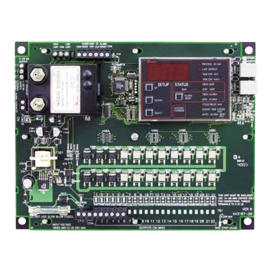
Thank you for purchasing the Dwyer
Controller. You have selected a state of the art dust collector timer control
that will provide years of dependable operation and service.
The Dwyer
®
DCT1000DC Dust Collector Timer Controller was designed to
be used with pulse-jet type dust collectors for on-demand or continuous
cleaning applications.
Continuous cleaning applications do not require external inputs and can
be used for time based "on-demand" cleaning through use of the cycle
delay feature.
For
on-demand
applications,
(DCP100A/200A) can be used to take full advantage of all the features the
DCT1000DC offers, or an external pressure switch can be used for
High/Low limit control.
The Dwyer
®
DCT1000DC was designed so that it is easy to use, thus
allowing for a quick and easy start up for your dust control applications.
The contents inside this installation and operating manual will guide you
through the features of the DCT1000DC and how they can be applied to
get the most out of your dust control requirements.
DWYER INSTRUMENTS, INC.
P.O. BOX 373 • MICHIGAN CITY, INDIANA 46361 U.S.A.
1.888.610.7664
Series DCT1000DC Dust Collector Timer Controller
Specifications – Installation and Operating Instructions
®
DCT1000DC Dust Collector Timer
the
plug-in
pressure
modules
www.calcert.com
15
10
20
5
25
0
30
SPECIFICATIONS
DCT1000DC Timer Controller:
Output Channels: 6, 10, & 22 channels.
Power Requirements: 10 - 30 VDC.
Solenoid Supply: 3A maximum per channel.
Fuse: 3A @ 250 VAC.
Temperature Limits: -40 to 140°F (-40 to 60°C).
Storage Temperature Limits: -40 to 176°F (-40 to 80°C).
On Time: 10 msec to 600 msec, 10 msec steps.
On Time Accuracy: ± 10 msec.
Off Time: 1 second to 255 seconds, 1 second steps.
Off Time Accuracy: ±1% of the value or ±50 msec, whichever is
greater.
Weight: 1 lb 3.0 oz (538.6 g).
Phone: 219/879-8000
Fax: 219/872-9057
Bulletin E-97DC
www.dwyer-inst.com
e-mail: info@dwyer-inst.com
sales@calcert.com
Advertisement
Table of Contents

Related Manuals for Dwyer Instruments DCT1010DC


Summary of Contents for Dwyer Instruments DCT1010DC
- Page 1 DCT1000DC and how they can be applied to get the most out of your dust control requirements. Phone: 219/879-8000 www.dwyer-inst.com DWYER INSTRUMENTS, INC. Fax: 219/872-9057 e-mail: info@dwyer-inst.com P.O. BOX 373 • MICHIGAN CITY, INDIANA 46361 U.S.A.
- Page 2 2-3/4 [69.85] PROCESS (IN H LAST OUTPUT TIME OFF (SEC) TIME ON (M SEC) SETUP STATUS HIGH LIMIT LOW LIMIT ALARM HIGH ALARM RESET DOWN LOW ALARM CYCLE DELAY (MIN) MANUAL DOWN TIME CYCLES OVERRIDE (MIN) SELECT AUTO ALARM RESET (SEC) 6-1/4 [158.75]...
-
Page 3: Table Of Contents
Table of Contents Page No. 1.2 DCT1000DC Terminal Connections Figure 1 Dimensional Specifications ....2 The line and solenoid connections are located at the lower edge of the Installing the DCT1000DC . -
Page 4: Manual Override Switch Connection
To connect multiple boards together you will need one or more jumper cables, Model DCA, available from Dwyer Instruments, Inc. in various 1.4.3 Connecting the Alarm Relay lengths. These are connected to the telephone-style connectors at the With the pressure module installed, a relay contact is provided for upper right side of the controller boards. -
Page 5: Dcp Installation
When inserting the module, the following procedure should be adhered to 1.3 DCP Installation insure proper installation: Caution: Prior to installing the DCP100A/200A please review the operating specifications carefully. • Examine the bottom of the pressure module and note the orientation of Some operating systems, especially in pneumatic conveying the connectors. -
Page 6: Connecting The Alarm Relay
ALARM ALARM HIGH LIMIT COM LIMIT MODE RESET COM MODE SELECTION SWITCH 4-20 MA OUTPUT REAR FRONT SECTION SECTION CONTINUOUS ON DEMAND DCT1000DC MASTER CONTROLLER (INTERNALLY CONNECTED) (10 CHANNEL SHOWN) OUTPUTS (3A MAX) Figure 4 (+) (-) L1 L2 Three Position Selection Switch Wiring LINE INPUT 1.5 Three Position Selection Switch Wiring 2.1 •... -
Page 7: High Limit Setup
2.5 • Low Limit [Only available when DCP installed] 3.0 Maintenance Support and Diagnostics The operation of the Low Limit, available only with a pressure module installed, is identical to the High Limit except this value sets the pressure We have also included a number of features that will aid maintenance where the cleaning cycle will end. -
Page 8: Error Codes
Contact the factory. Still need help? Please feel free to contact one of our customer service representatives or visit us on the web at www.dwyer-inst.com. Thank you for choosing Dwyer Instruments, Inc. FR# 443123-05 Rev. 3 ©Copyright 2010 Dwyer Instruments, Inc.
Need help?
Do you have a question about the DCT1010DC and is the answer not in the manual?
Questions and answers