Dwyer Instruments Series DH3 Digihelic Operating And Installation Instruction
Differential pressure controller
Hide thumbs
Also See for Series DH3 Digihelic:
- Installation and operating instructions manual (20 pages) ,
- Installation and operating instructions manual (20 pages)
Advertisement
Quick Links
DWYER INSTRUMENTS, INC.
P.O. BOX 373 • MICHIGAN CITY, IN 46360, U.S.A.
QualityInstruments-Direct
Series DH3 Digihelic
Specifications - Installation and Operating Instructions
Differential Pressure Controller
®
Phone: 219/879-8000
Fax: 219/872-9057
Bulletin B-30
www.dwyer-inst.com
e-mail: info@dwyer-inst.com
1.800.868.
.ca
Advertisement

Related Manuals for Dwyer Instruments Series DH3 Digihelic


Summary of Contents for Dwyer Instruments Series DH3 Digihelic
- Page 1 Bulletin B-30 Series DH3 Digihelic Differential Pressure Controller ® Specifications - Installation and Operating Instructions DWYER INSTRUMENTS, INC. Phone: 219/879-8000 www.dwyer-inst.com P.O. BOX 373 • MICHIGAN CITY, IN 46360, U.S.A. Fax: 219/872-9057 e-mail: info@dwyer-inst.com QualityInstruments-Direct 1.800.868.
- Page 2 DIMENSIONS 2-1/16 (4) 6-32 HOLES (52.39) EQUALLY SPACED ON A 5-1/8 (130.18) B.C. PANEL MOUNTING (50.80) 1/8 FEMALE NPT HIGH PRESSURE CONNECTION 1-1/4 (31.75) ø4-47/64 Ø5 (120.25) (127.00) 1/8 FEMALE NPT LOW PRESSURE CONNECTION Ø4 (101.60) 5/8 (15.88) FACE PANEL MAX 5-1/2 (139.70) O.D.
-
Page 3: Installation
INSTALLATION LOCATION: Select a clean, dry location free from shock and vibration where temperature limits will not be exceeded. Distance from the transmitter to the receiver is limited only by total loop resistance. See ELECTRICAL CONNECTIONS. Tubing feeding pressure to the instrument can be practically any length required, but long lengths will increase response time slightly. - Page 4 MOUNTING: The DH 3 may be either panel (flush) mounted or surface mounted. Panel Mounting - Cut a 4-13/16˝ or 122 mm diameter hole in the panel and insert the unit from the front. Slip on the mounting ring with the stepped side facing rear. Next, fit the snap ring into the narrow groove at back edge of bezel.
- Page 5 WIRING The DH 3 uses a standard 15 pin male high density D-Sub connector available from most electronic distributors. A pre-wired 18˝ cable is included with each unit. See below table for cable color wiring information. Function 15 PIN Connector Cable Color Terminal 12-24 VAC/VDC Power...
-
Page 6: Key Functions
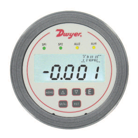
FRONT PANEL SP2 DESCRIPTOR SP1 DESCRIPTOR ALARM DESCRIPTOR MULTIPLIER ALLO ALLO ALHI ALHI DESCRIPTOR VISABLE WITH SOME VELOCITY INWC INWC UNITS AND FLOW RANGES 1.000 1.000 INPUT VALUE MENU MENU SP/AL SP/AL KEY FUNCTIONS Home Main Menu Function Sub Menu Function Position Function Sequences the display Return to home... -
Page 7: Set Point Adjustment
SETTING SET POINTS AND ALARMS hot key provides direct access to the Set Point and Alarm MENU. The Set SP/AL SP/AL Point and Alarm MENUS that are displayed are based upon the Control (CtrL) SUB MENU. CONTROL MODE CONTROL MODE CONTROL MODE CONTROL MODE CONTROL MODE CONTROL MODE... - Page 8 MENU MAP MENU MAP MAIN MENUS SUB MENUS SETTINGS SETTINGS MENUS UNAVAILABLE BI-DIRECTIONAL RANGES AND RANGES ABOVE 25 IN. W.C. CONTINUED CONTINUED QualityInstruments-Direct 1.800.868. MENU MENU...
- Page 9 SETTINGS SETTINGS MAIN MENUS SUB MENUS 0PEn CONTINUED CONTINUED MENU MENU QualityInstruments-Direct 1.800.868.
- Page 10 SETTINGS MAIN MENUS SUB MENUS Menus present only in pressure operation MENU MENU QualityInstruments-Direct 1.800.868.
- Page 11 Main Menu Selections (Upper Right Display Reads MENU ) Security - Lock out access to Set Point and Alarm settings, or lock out access to SECr all settings. OPEr Operation - Selection of Pressure, Velocity or Flow and corresponding engineering units.
- Page 12 MAIN MENUS and SUB MENUS SECr (Security) MAIN MENU SECr is the only SUB MENU in the security MENU. When the security SUB MENU is selected, the present security level is displayed in the upper right hand display. To change the security level, adjust the number displayed to the number shown in the following table for the desired security level.
- Page 13 PrES (Pressure) SUB MENU For pressure measurement, the following units are available: INWC - Inches of water column MMHG - Millimeters of mercury FTWC - Feet of water column MBAR - Millibar MMWC - Millimeters of water column PA - Pascal CMWC - Centimeters of water column KPA - Kilopascals PSI - Pounds per square inch...
- Page 14 FLO (Flow) SUB MENU For flow measurements the following units are available: SCFM - Standard cubic feet per minute M^3H - Cubic meters per hour FLO r (Flow Range) SUB MENU LO - 99.99 x 1K flow range HI - 999.9 x 1K flow range Tables 3-6 show the flow ranges available, and the maximum duct size that can be set for each input range.
- Page 15 ArEA , DIA , XDIM and YDIM SUB MENUS These SUB MENUS become accessible if the instrument is set for flow. When measuring flow, the area of the duct must be specified. Tables 3 and 4 show the input range vs max- imum flow and duct size.
- Page 16 CtrL (Control) SUB MENU 1SP - Single set point 2SP - Two fully independent set points SPAL - Single set point and alarm 1SP (SP1 Reverse or Direct Acting) SUB MENU DIR - Direct. Relay turns on with increasing pressure REV - Reverse. Relay turns on with decreasing pressure Relay Inactive Relay Active Relay Inactive...
-
Page 17: Alarm Adjustment
The following alarm function SUB MENUS are activated when CtrL is set to SPAL : AL (Alarm Type) SUB MENU HI - High alarm LO - Low alarm HILO - For a high/low guardband type alarm ALARM ADJUSTMENT Alarm settings are dependent upon the selected alarm mode. The DH3 differential pres- ®... - Page 18 AL0S (Alarm Output State) SUB MENU CL0S - Alarm relay contacts close upon alarm condition 0PEN - Alarm relay contacts open upon alarm condition ALrE (Alarm Reset) SUB MENU ONOF - Automatic reset HOLD - Manual reset. An alarm is reset by the RESET key on the front panel, or an external reset switch.
- Page 19 rESO (Resolution) SUB MENU The DH 3 is capable of displaying four digits of resolution. However, at very low pressures the instability of the pressure may cause fluctuations in the least significant digit causing the least significant digit to be of little value. Three digit resolution ( 3DIG ) can only be active when there is at least one digit to the right of a decimal.
- Page 20 With the display set to SPAN , apply full scale pressure to the unit. Press the ENTER key. The upper display will blink. Press ENTER again to complete the calibration or press the MENU key to cancel. ©Copyright 2012 Dwyer Instruments, Inc. Printed in U.S.A. 2/12 FR# 443555-00 Rev.3 DWYER INSTRUMENTS, INC.
Need help?
Do you have a question about the Series DH3 Digihelic and is the answer not in the manual?
Questions and answers