
Related Manuals for NAVITAS TSE Series


Summary of Contents for NAVITAS TSE Series
- Page 1 TSE & PSE Installation Manual Navitas Technologies Ltd. C-855 Trillium Dr. Kitchener, Ontario N2R 1J9 Canada Phone: (519) 725-7871 Fax: (519) 725-1645 www.navitastechnologies.com...
- Page 3 TSE & PSE Installation Manual Thank you for purchasing a Navitas Technologies motor controller. With proper installation and setting of the parameters, your Controller will give you years of trouble free operation, with a level of adjustability never before available.
-
Page 4: Cable Connections
“Diagram #1”. Then connect each of the control wires from the Navitas harness to their appropriate input or output. This concludes the control wiring installation. - Page 5 50% with the ProBit after installation. Should you wish to install your motors in series, please refer to the Application Note #3 (D Contactor) in the Navitas Service and Product manual, or download the Note from our Technical Support area on our Website at http://www.navitastechnologies.com For systems that require tight turn inside wheel reversing instead of the standard drop-out only, please see the TTR50 installation procedure on the next page.
- Page 6 The rest of the instructions apply to both configurations: Install the TTR in a convenient location (the top of the Navitas Controller is a good choice (using double faced tape) and wire exactly as shown in Wiring Diagram #3. Limit 1 and Limit 2 on the TTR are wired to the limit switch inputs B4 (wh/brn) and B3 (wh/org) on the TSE1000.
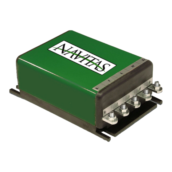
- Page 7 Not used ** At least one of the level switches OR the accelerator must be used. CABLE CONNECTIONS: “B+” and “B-“ on Navitas Battery Positive and Negative “A” on Navitas Armature terminal on motor “F” on Navitas Field terminal on motor *** *** Reversing “A”...
- Page 8 PSE-P. #6- THE NAVITAS PROBIT The Navitas Technologies ProBit is a combination Installation and Customizing tool as well as a very efficient diagnostics and trouble-shooting aid. It consists of simple pull-down menus arranged in four main groups:...
- Page 9 SETTING UP YOUR NEW CONTROLLER WITH THE PROBIT: After any of the Navitas Controllers has been installed, it needs to be set up with the ProBit. The ProBit will run a whole set of tests to ensure that the controller(s) has been properly installed and that the peripheral components such as motors and contactors are in working order.
- Page 10 Should you experience any problems or have any questions during the installation or set-up procedures, do not hesitate to call and ask for help. Five minutes spent on the phone with us may save you hours of frustrations and troubleshooting later. Navitas Technologies Ltd. Last Updated: 6/13/2006 Page 8...
- Page 11 TSE & PSE Installation Manual Navitas Technologies Ltd. Last Updated: 6/13/2006 Page 9...
- Page 12 TSE & PSE Installation Manual Navitas Technologies Ltd. Last Updated: 6/13/2006 Page 10...
- Page 13 TSE & PSE Installation Manual Navitas Technologies Ltd. Last Updated: 6/13/2006 Page 11...
- Page 14 TSE & PSE Installation Manual CAUTION: It is very important that suppressors and blocking diodes be used on all directional contactors as indicated above. Navitas Technologies Ltd. Last Updated: 6/13/2006 Page 12...
Need help?
Do you have a question about the TSE Series and is the answer not in the manual?
Questions and answers