
Related Manuals for Daikin RXF125KC


Summary of Contents for Daikin RXF125KC
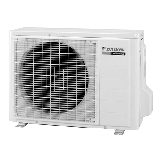
- Page 1 Si001157 REMOVAL PROCEDURE S E R V I C E M A N U A L 2.5/3.5 kW Class Outdoor Unit Inverter Pair Type...
- Page 2 Service Manual Removal Procedure Outdoor Unit Applicable Models Heat Pump RXF125KC RXF135KC RZS235KC RZS235KCG RZS235KCP RZS235KCS...
-
Page 3: Table Of Contents
Si001157 Table of Contents 1. Removal of Outer Panels / Fan Motor.............2 2. Removal of Electrical Box ...............9 3. Removal of PCBs..................12 4. Removal of Reactor / Partition Plate .............17 5. Removal of Sound Blankets..............19 6. Removal of Thermistor ASSY ...............21 7. -
Page 4: Removal Of Outer Panels / Fan Motor
Removal of Outer Panels / Fan Motor Si001157 1. Removal of Outer Panels / Fan Motor Procedure Warning Be sure to wait for 10 minutes or more after turning off all power supplies before disassembling work. Procedure Points Step 1. Appearance features (R7186) Take care not to cut your finger by the fins of the... - Page 5 Si001157 Removal of Outer Panels / Fan Motor Step Procedure Points Remove the 2 screws Top panel and lift the top panel. (R7190) Remove the drip proof Drip proof plate plate. (R7191) Remove the 4 screws and remove the discharge grille. Discharge grille (R12569) The discharge grille has 4...
- Page 6 Removal of Outer Panels / Fan Motor Si001157 Step Procedure Points Remove the 8 screws of the front panel. Front panel (R12571) Unfasten the hooks. The front panel has 4 hooks. Pull and remove the front panel. Hook (R12572) 3. Remove the fan motor. Nut size: M6 Remove the nut of the outdoor fan.
- Page 7 Si001157 Removal of Outer Panels / Fan Motor Step Procedure Points Release the outdoor temperature thermistor. Outdoor temperature thermistor (R11829) Disconnect the connector for the fan motor [S70]. [S70] (R15680) Release the fan motor Fan motor lead wire from the hook. lead wire (R12576) Removal Procedure...
- Page 8 Removal of Outer Panels / Fan Motor Si001157 Step Procedure Points Remove the screw of the fan motor fixing frame. Fan motor fixing frame (R12577) Lift and remove the fan When reassembling, fit the motor fixing frame. lower hooks into the bottom frame.
- Page 9 Si001157 Removal of Outer Panels / Fan Motor Step Procedure Points Release the fan motor When reassembling, put the lead wire from the 2 fan motor lead wire through hooks. the back of the fan motor so as not to be entangled with the outdoor fan.
- Page 10 Removal of Outer Panels / Fan Motor Si001157 Step Procedure Points Lift up the right side When reassembling, make panel and remove it. sure to fit the hook. Hook (R12585) Removal Procedure...
-
Page 11: Removal Of Electrical Box
Si001157 Removal of Electrical Box 2. Removal of Electrical Box Procedure Warning Be sure to wait for 10 minutes or more after turning off all power supplies before disassembling work. Procedure Points Step Disconnect the 2 Preparation connectors for the Remove the panels and reactor. - Page 12 Removal of Electrical Box Si001157 Step Procedure Points Disconnect the [S40] connector for the overload protector [S40]. (R12589) Disconnect the connector for the electronic expansion valve coil [S20]. (R12590) [S20] Disconnect the connector for the four way valve coil [S80]. [S80] (R12591) Removal Procedure...
- Page 13 Si001157 Removal of Electrical Box Step Procedure Points Lift and remove the Electrical box electrical box. (R13179) Removal Procedure...
-
Page 14: Removal Of Pcbs
Removal of PCBs Si001157 3. Removal of PCBs Procedure Warning Be sure to wait for 10 minutes or more after turning off all power supplies before disassembling work. Procedure Points Step 1. Remove the main PCB. You can remove the main PCB when you disconnect Feature of the main the lead wires on the... - Page 15 Si001157 Removal of PCBs Step Procedure Points Disconnect the connector for the filter PCB [S10]. [S10] (R12596) Disconnect the connector for the filter PCB [HL3]. [HL3] (R12598) Disconnect the connector for the filter PCB [HN3]. [HN3] (R12599) Remove the 6 screws. (R12600) Removal Procedure...
- Page 16 Removal of PCBs Si001157 Step Procedure Points Unfasten the 2 hooks The electrical box has also 2 on the lower side. hooks on the upper side. When reassembling, be sure to fit all the 4 hooks. (R13201) Lift and pull out the main PCB.
- Page 17 Si001157 Removal of PCBs Step Procedure Points 2. Remove the filter PCB. Remove the 2 screws and release the earth wires. Earth wire (R17485) Disconnect the 1 : black, upper connectors from the 2 : white, lower terminal board. 3 : red, upper : green, lower (R12605) Release the harnesses...
- Page 18 Removal of PCBs Si001157 Step Procedure Points Release the harnesses from the hook. (R12607) Remove the screw. (R12608) Unfasten the 2 hooks and remove the filter PCB. Filter PCB (R12609) (R12610) Removal Procedure...
-
Page 19: Removal Of Reactor / Partition Plate
Si001157 Removal of Reactor / Partition Plate 4. Removal of Reactor / Partition Plate Procedure Warning Be sure to wait for 10 minutes or more after turning off all power supplies before disassembling work. Procedure Points Step 1. Remove the reactor. Preparation Reactor Remove the screw and... - Page 20 Removal of Reactor / Partition Plate Si001157 Step Procedure Points The partition plate has When reassembling, fit the 2 hooks on the lower lower hooks into the bottom side. Lift and pull the frame. partition plate and remove it. Hook (R12614) Removal Procedure...
-
Page 21: Removal Of Sound Blankets
Si001157 Removal of Sound Blankets 5. Removal of Sound Blankets Procedure Warning Be sure to wait for 10 minutes or more after turning off all power supplies before disassembling work. Procedure Points Step Untie the string and Preparation open the sound blanket Remove the panels (outer). - Page 22 Removal of Sound Blankets Si001157 Step Procedure Points Pull the sound blanket Since the piping ports are (inner) out. torn easily, remove the sound blanket carefully. Sound blanket (inner) (R12618) Removal Procedure...
-
Page 23: Removal Of Thermistor Assy
Si001157 Removal of Thermistor ASSY 6. Removal of Thermistor ASSY Procedure Warning Be sure to wait for 10 minutes or more after turning off all power supplies before disassembling work. Procedure Points Step Release the discharge Be careful not to lose the clip Discharge pipe thermistor pipe thermistor. -
Page 24: Removal Of Four Way Valve
Removal of Four Way Valve Si001157 7. Removal of Four Way Valve Procedure Warning Be sure to wait for 10 minutes or more after turning off all power supplies before disassembling work. Procedure Points Step Pull out the electronic expansion valve coil. Electronic expansion valve coil... - Page 25 Si001157 Removal of Four Way Valve Step Procedure Points Remove the screw and Four way valve coil remove the four way Warning valve coil. Be careful not to get yourself burnt with the pipes and other parts that are heated by the gas brazing machine.
- Page 26 Removal of Four Way Valve Si001157 Step Procedure Points Note: Do not use a metal saw for cutting pipes by all means because the sawdust comes into the circuit. When withdrawing the pipes, be careful not to pinch them firmly with pliers. The pipes may get deformed.
-
Page 27: Removal Of Compressor
Si001157 Removal of Compressor 8. Removal of Compressor Procedure Warning Be sure to wait for 10 minutes or more after turning off all power supplies before disassembling work. Procedure Points Step Remove the 3 nuts of the compressor. Warning Be careful not to get yourself burnt with the pipes and other parts that are heated by the gas brazing machine. - Page 28 Removal of Compressor Si001157 Step Procedure Points Heat up the brazed part Note: of the suction side and Do not use a metal saw for disconnect. cutting pipes by all means because the sawdust comes into the circuit. When withdrawing the pipes, be careful not to pinch them firmly with pliers.
- Page 29 Revision History Month / Year Version Revised contents 08/2012 Si001157 First edition...
- Page 30 Improper installation can result in water or refrigerant leakage, electrical shock, fire or explosion. Use only those parts and accessories supplied or specified by Daikin. Ask a qualified installer or contractor to install those parts and accessories. Use of unauthorised parts and accessories or improper installation of parts and accessories can result in water or refrigerant leakage, electrical shock, fire or explosion.
Need help?
Do you have a question about the RXF125KC and is the answer not in the manual?
Questions and answers