
Related Manuals for Rockwell Automation AllenBradley 432ES-IG3


Summary of Contents for Rockwell Automation AllenBradley 432ES-IG3
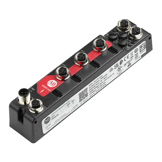
- Page 1 GuardLink EtherNet/IP Interface Catalog Number 432ES-IG3 User Manual Original Instructions...
- Page 2 If this equipment is used in a manner not specified by the manufacturer, the protection provided by the equipment may be impaired. In no event will Rockwell Automation, Inc. be responsible or liable for indirect or consequential damages resulting from the use or application of this equipment.
-
Page 3: Table Of Contents
Channels Page ..........40 Rockwell Automation Publication 432ES-UM001A-EN-P - September 2022... - Page 4 CE Conformity ..........88 Rockwell Automation Publication 432ES-UM001A-EN-P - September 2022...
- Page 5 Index ............101 Rockwell Automation Publication 432ES-UM001A-EN-P - September 2022...
- Page 6 Table of Contents Notes: Rockwell Automation Publication 432ES-UM001A-EN-P - September 2022...
-
Page 7: About This Publication
If you do not, obtain the proper training before using this product. IMPORTANT Read and thoroughly understand the manual before installing or operating a system that contains this device. Rockwell Automation Publication 432ES-UM001A-EN-P - September 2022... -
Page 8: Definitions
The on-state of the output of a logic block, or the state of an input to a logic block, or a voltage level that is above the turn-on threshold. HI is equivalent to a Boolean value of Human Machine Interface - A Rockwell Automation® product in the PanelView™ family. Host The host is the 432ES-IG3 network interface module. -
Page 9: Additional Resources
Industrial Automation Wiring and Grounding Guidelines, publication 1770-4.1 Provides general guidelines for installing a Rockwell Automation industrial system. Product Certifications website, rok.auto/certifications. Provides declarations of conformity, certificates, and other certification details. You can view or download publications at rok.auto/literature. - Page 10 Preface Notes: Rockwell Automation Publication 432ES-UM001A-EN-P - September 2022...
-
Page 11: Overview
Passive Power Tap over EtherNet/IP 432ES-IG3 network interface module can control up to three safety zones, one zone for each GuardLink channel. With logic, the channels can combine to control only one or two zones. Rockwell Automation Publication 432ES-UM001A-EN-P - September 2022... -
Page 12: Requirements
Module Power status indicator Status Indicator Power Out Power Out Power In Power In 4-Pin M12 A-code 4-Pin M12 A-code 4-Pin M12 A-code Micro Style 4-Pin M12 A-code Micro Style Micro Style Micro Style Rockwell Automation Publication 432ES-UM001A-EN-P - September 2022... -
Page 13: Modes Of Operation
Passive power taps that interface with devices that are GuardLink-enabled and add power to the link GuardLink-enabled taps are available in an 8-pin and 5-pin device connection version. Passive style taps are only available in a 5-pin device connection version. Rockwell Automation Publication 432ES-UM001A-EN-P - September 2022... -
Page 14: Tap Connections
To minimize the voltage drop due to wire resistance, the preferred wiring gauge for the link cable is 18 AWG (0.823 mm2). Visit rockwellautomation.com/en-us/products/hardware/allen-bradley/ connection-devices/cables-and-cordsets/dc-micro--m12-/dc-micro-cordsets- and-patchcords.html for other options, such as right-angle connectors, stainless-steel couplings, and shielded cables. Rockwell Automation Publication 432ES-UM001A-EN-P - September 2022... - Page 15 Power 30 m (98.4 ft) length, max Wire Cordset Relay Supply between GuardLink-enabled Devices 30 m (98.4 ft) length, max (includes link and device cables) All lengths 30 m (98.4 ft) length, max Rockwell Automation Publication 432ES-UM001A-EN-P - September 2022...
-
Page 16: Tap Replacement
Discover Modules feature to add the nodes to the Controller Organizer quickly, in the correct order, with the correct part number, and compatible electronic keying. Rockwell Automation Publication 432ES-UM001A-EN-P - September 2022... -
Page 17: Terminator
Modifications to the GuardLink circuit are only realized upon power-up with the terminator in place. For a simple power-up, break the link signal at any point in the circuit before the device that last had the terminator. Rockwell Automation Publication 432ES-UM001A-EN-P - September 2022... -
Page 18: Commissioning Example
15 at once. After moving the terminator, cycle power to the tap or switch from where the terminator is removed. Reapply power to the channel after you install the terminator in its new location. Rockwell Automation Publication 432ES-UM001A-EN-P - September 2022... -
Page 19: Approximate Dimensions
Use a flat and lock washer; mount the flat washer underneath the lock washer. Torque the mounting screws to 0.68 N•m (6 lb•in). Rockwell Automation Publication 432ES-UM001A-EN-P - September 2022... -
Page 20: Cable Clearance
432ES-IG3 network interface module that is mounted against a side wall with all cables using right-angle quick-disconnect connectors. Figure 11 - Side Mounting with Right-angle Connectors EtherNet/IP™ Link 1 EtherNet/IP Link 2 432ES-IG3 GuardLink® Channels Power Connections Rockwell Automation Publication 432ES-UM001A-EN-P - September 2022... -
Page 21: Wiring
Figure 12 - Pin Assignments Table 2 on page 22 Table 4 on page 22 Table 5 on page 22 Table 3 on page 22 Rockwell Automation Publication 432ES-UM001A-EN-P - September 2022... - Page 22 (1) x = 2 [2 m (6.6 ft)], 5 [5 m (16.4 ft)], 10 [10 m (32.8 ft)], 15 [15 m (49.21 ft)], 20 [20 m (65.62 ft)], or 30 [30 m (98.42 ft)] for standard cable lengths. For other cable lengths, contact your local Allen-Bradley product distributor or Rockwell Automation sales office.
-
Page 23: Power Supply
The DC power supply must satisfy the requirements for the National Electric Code (NEC) Class 2 and ground to protective earth. Many of the Bulletin 1606 power supplies from Rockwell Automation are both PELV and NEC Class 2 compliant. Following is a list of compliant supplies. -
Page 24: Multiple Power Supplies
The power supply has a 96…264 AC input and supplies a 24V DC supply, which meets NEC Class 2 with an earth grounded 0V terminal. Figure 14 - Multiple Power Supplies 440S-PF5D4 Passive Power Tap INPUT INPUT DC ok DC ok 24… 24… 1606-XLP95E 1606-XLP95E Rockwell Automation Publication 432ES-UM001A-EN-P - September 2022... -
Page 25: Set The Ip Address
To set the IP address, obtain the following: • EtherNet/IP driver installed on the programming workstation • MAC ID from the device, which is on the label on the side of the device • Recommended IP address for the device Rockwell Automation Publication 432ES-UM001A-EN-P - September 2022... -
Page 26: Alternative Methods To Set The Ip Address
The tap or 440G-MZ safety switch must have a network connection to the controller. • The controller must be online (Rem Run, Rem Prog, or Rem Test). • The controller must be Safety Unlocked. Rockwell Automation Publication 432ES-UM001A-EN-P - September 2022... - Page 27 6. Click Apply, and then click Yes to confirm in the follow-up window. Figure 16 - Inhibit Node IMPORTANT When your update completes, return to the Connection page and clear the inhibit check boxes for all devices. Rockwell Automation Publication 432ES-UM001A-EN-P - September 2022...
-
Page 28: Update Firmware
In Figure 19 on page 29, there is only one device on channel 0. 3. Click Settings and select the Firmware Locations tab to navigate to the firmware on your computer. Rockwell Automation Publication 432ES-UM001A-EN-P - September 2022... - Page 29 5. Check the box of the device that you want to update. Figure 20 - Select the Device to Update 6. Click Next. 7. Click Flash. 8. When the update is complete, click Close. 9. Click Done. Rockwell Automation Publication 432ES-UM001A-EN-P - September 2022...
-
Page 30: Install The Profile
Use the Studio 5000 Logix Designer application to open or create a controller project. Module to a Controller 1. Right-click the Ethernet module of the controller with which you want to Project communicate and select New Module. Rockwell Automation Publication 432ES-UM001A-EN-P - September 2022... -
Page 31: View Module Profile Properties
To view information about the module profile, right-click the New Module title bar (or Module Properties after installation), and then click About Module Profile. The example in Figure 25 on page 32 shows 1.00.20.0 as the specific software version of the profile. Rockwell Automation Publication 432ES-UM001A-EN-P - September 2022... -
Page 32: General Page
Add the Network Interface Module Figure 25 - Software Version Installed Right-click on the title bar General Page Figure 26 shows the General page for the 432ES-IG3 network interface module. Figure 26 - General Page Rockwell Automation Publication 432ES-UM001A-EN-P - September 2022... - Page 33 In Time-based format, click the Generate button to create an SNN. • Check the Manual format and edit the number. • Paste the number from your cache (for example, the SNN copied from the controller). This option automatically changes the format to Time-based. Rockwell Automation Publication 432ES-UM001A-EN-P - September 2022...
- Page 34 SNN that resides in the controller. To download the SNN to the 432ES-IG3 network interface module, inhibit the module on the Connection page, and then reset ownership of the interface on the Safety page. Rockwell Automation Publication 432ES-UM001A-EN-P - September 2022...
-
Page 35: Connection Page
The node tag values remain unchanged until the inhibit is removed. Figure 30 on page 36 shows an example with the inhibited 432ES-IG3 network interface module. On the node devices (taps and switches), the Link indicators Rockwell Automation Publication 432ES-UM001A-EN-P - September 2022... -
Page 36: Safety Page
Device indicators on all three channels flash green. Figure 30 - Module Inhibited Safety Page Figure 31 shows an example of the Safety page with an online controller project. Figure 31 - Safety Page Rockwell Automation Publication 432ES-UM001A-EN-P - September 2022... - Page 37 ATTENTION: Add the connection reaction time limit for the safety inputs to the total response time in the GuardLink circuit and safety devices to calculate the safety distance. Figure 32 - Advanced Connection Reaction Time Limit Configuration Rockwell Automation Publication 432ES-UM001A-EN-P - September 2022...
- Page 38 7. From the Connection page, uncheck the Inhibit Module box and click Apply. 8. The SNN passes to the device. On the Safety page, Configuration Ownership shows Local. Now the controller and 432ES-IG3 network interface module SNN match. Rockwell Automation Publication 432ES-UM001A-EN-P - September 2022...
-
Page 39: Module Info Page
The 432ES-IG3 network interface module is in a running state with no major or minor faults. The module is configured and owned, and the module identity is a match for electronic keying. Figure 35 - Module Info Page Rockwell Automation Publication 432ES-UM001A-EN-P - September 2022... -
Page 40: Channels Page
When a channel is not used, the channel Fault bit sets to 1 and the channel SIL 3 Status tag sets to 0. On the 432ES network interface module, the channel indicator flashes red. Rockwell Automation Publication 432ES-UM001A-EN-P - September 2022... -
Page 41: Internet Protocol Page
After you make changes, click the Set button, which enables as you make changes. Figure 37 - Internet Protocol Page The ideal basic settings are: • Manually configure IP settings • Physical Module IP Address - Shows an assigned address • Subnet mask - 255.255.255.0 Rockwell Automation Publication 432ES-UM001A-EN-P - September 2022... -
Page 42: Port Configuration Page
When Auto-Negotiate is checked, the Set button is disabled. When Auto-Negotiate is unchecked, the Set button is enabled. After you adjust the configuration, click the Set button to download the changes to the 432ES-IG3 network interface module. Rockwell Automation Publication 432ES-UM001A-EN-P - September 2022... -
Page 43: Network Page
• Star topology - Consists of a number of modules that connect to a central switch. Modules can be added or removed without affecting the rest of the network. Rockwell Automation Publication 432ES-UM001A-EN-P - September 2022... -
Page 44: Time Sync Page
In either method, the controller can be in Rem Run, Rem Prog, or Rem Test mode, and the controller can be either Safety Unlocked or Safety Locked. If the controller is offline, you can only add nodes manually. Rockwell Automation Publication 432ES-UM001A-EN-P - September 2022... -
Page 45: Manual Method
In the example shown in Figure 43 on page 46, Ch0 already has two nodes. Additional nodes are added to the GuardLink circuit, then added to the controller tree with the Discover Modules feature. Rockwell Automation Publication 432ES-UM001A-EN-P - September 2022... - Page 46 The table also shows the firmware revision of the device and additional information. 2. Click the Create button for a node to add the node to the controller tree. Figure 44 - Select New Module Type Rockwell Automation Publication 432ES-UM001A-EN-P - September 2022...
- Page 47 Fault tag to 1, which sets its Tripped tag to 1, which finally sets its channel Status tag to 0 (a safe state). 9. Once you complete all necessary changes, click OK. Rockwell Automation Publication 432ES-UM001A-EN-P - September 2022...
- Page 48 Figure 46 - Online Module Creation Message The Module Info page (Figure 47) populates after the module is created and the module is online. Figure 47 - Example Module Info Page for a Node Rockwell Automation Publication 432ES-UM001A-EN-P - September 2022...
-
Page 49: Overview
You can make a limited number of changes to the nodes while the controller is in the Safety Locked mode. If you need to download the configuration to the controller, first change the controller mode Safety Unlock. Rockwell Automation Publication 432ES-UM001A-EN-P - September 2022... -
Page 50: Node Tags Used In Routines
Pt.Data tag sets to 1. In Figure 49 on page The MainProgram tab shows that a safety demand is placed on the Black node (Node 0), while all other nodes have no safety demand. Rockwell Automation Publication 432ES-UM001A-EN-P - September 2022... - Page 51 (IO Faulted), an Invalid link address. - On the 432ES network interface module, the CH0 indicator flashes red. - On the taps, the Link status indicators are steady red, and the Device status indicators flash green. Rockwell Automation Publication 432ES-UM001A-EN-P - September 2022...
- Page 52 4 and 5 because the logic is associated with the node name, not the node number. 3. See Figure 52 on page 53. Take the controller offline 4. Change the node position from 5 to 6. 5. Click OK. Rockwell Automation Publication 432ES-UM001A-EN-P - September 2022...
- Page 53 Figure 53 - Add a New Module Figure 54 on page 54 shows the Select Module Type window. Type 440S in the filter field. 9. Highlight the tap that you want to add and click Create. Rockwell Automation Publication 432ES-UM001A-EN-P - September 2022...
- Page 54 Figure 55 - Assign Name to New Module 11. The Blue node appears in position 4. You can now add code to the Main Routine to capture the event when the Blue node trips, see Figure 56 on page Rockwell Automation Publication 432ES-UM001A-EN-P - September 2022...
- Page 55 Figure 56 - Blue Added to Main Routine 12. In Figure 57, the changes download to the controller. Figure 57 - Download to Controller 13. Read the download messages in Figure 58 on page 56. Click Download. Rockwell Automation Publication 432ES-UM001A-EN-P - September 2022...
- Page 56 Figure 59, set the mode back to Safety Locked. Figure 59 - Set Controller Mode to Safety Locked Figure 60 on page 57 shows that the 432ES-IG3 network interface module system is Running. Rockwell Automation Publication 432ES-UM001A-EN-P - September 2022...
-
Page 57: Change A Node
When you install the new tap with the link cables connected and the new switch operational, the Logix Designer application reports an electronic keying error at node 4. The CH0 channel tags remain unchanged (see Figure 61 on page 58). Rockwell Automation Publication 432ES-UM001A-EN-P - September 2022... - Page 58 62, right-click on the node and then click Delete. Figure 62 - Delete Node 4 2. The Logix Designer application presents a danger warning(Figure 63 on page 59). Click Yes if no danger exists. Rockwell Automation Publication 432ES-UM001A-EN-P - September 2022...
- Page 59 5. In this example, none of the tags for node 4 are used in a program routine. Therefore, you can assign a unique name to the node or assign the same name as the node it replaced. 6. To apply the name, click OK, then close the window. Rockwell Automation Publication 432ES-UM001A-EN-P - September 2022...
- Page 60 As shown in Figure 67 on page 61, the new 440S-SF5D tap replaces the 440S-SF8D tap at node position 4, and CH0 transitions to an operational state with Status at a value of 1. Rockwell Automation Publication 432ES-UM001A-EN-P - September 2022...
-
Page 61: Append A Node
CH0 in the Logix Designer application first. The node shows a fault message (Invalid link address). Although a new node is appended, the CH0 Status remains at 1 (in an operational state) since the hardware has not changed. Rockwell Automation Publication 432ES-UM001A-EN-P - September 2022... - Page 62 - Node 6 shows a fault (Invalid link address). Figure 70 - Remove the Terminator 432ES-IG3 INPUT INPUT INPUT INPUT INPUT INPUT INPUT Node 0 2. Remove the terminator from node 6 (see Figure 70). Rockwell Automation Publication 432ES-UM001A-EN-P - September 2022...
-
Page 63: Delete A Node
In this example, the program routines do not use any tags from the last node. The controller is online, and Safety Locked. The CH0 Status tag is 1 (in an operational state). See Figure 73 on page 1. Right-click the node and click Delete. Rockwell Automation Publication 432ES-UM001A-EN-P - September 2022... - Page 64 CH0 transitions to a safe state; the Status tag shows 0. Figure 75 - Node is Removed - Ch0 Transitions to a Safe State 3. Remove the node 7 hardware. a. Remove the Link In cable to node 6. Rockwell Automation Publication 432ES-UM001A-EN-P - September 2022...
- Page 65 Reconnect the Link In cable to node 6. Figure 76 shows node 6 is now the GuardLink Safety Source. The CH0 Status bit returns to a value of 1 (operational state). Figure 76 - Last Node Successfully Removed Rockwell Automation Publication 432ES-UM001A-EN-P - September 2022...
- Page 66 Chapter 5 Modify GuardLink Topology Notes: Rockwell Automation Publication 432ES-UM001A-EN-P - September 2022...
-
Page 67: Interface Input Tags
For example, if the 24V supply drops momentarily to 16V and returns to 24V. The diagnostic sequence count increments by 2 (by 1 for the transition to 16V and again by 1 for the transition back to 24V). Rockwell Automation Publication 432ES-UM001A-EN-P - September 2022... - Page 68 Ch0.UnverifiedDevice BOOL fault. • 0 = All devices have been verified • 1 = Unverified devices present Indicates the number of client devices (hardware) Ch0.DeviceCount SINT detected on the channel. Rockwell Automation Publication 432ES-UM001A-EN-P - September 2022...
- Page 69 Network speed. • 10 = 10 Mbps Port1.Speed • 100 = 100 Mbps • 1000 = 1000 Mbps (not supported by the 432ES-IG3 network interface module) AB:Etherne Port2 t_Port_Cha See descriptions in Port1. nnel:S:1 Rockwell Automation Publication 432ES-UM001A-EN-P - September 2022...
- Page 70 This value is zero and the first-time stamp LocalClockOffsetTimestamp No LINT occurs when the module synchronizes with the Grandmaster clock. The EUI-64 Identity of the CIP Sync™ Grandmaster clock to GrandMasterClockID SINT[8] which the module is synced. Rockwell Automation Publication 432ES-UM001A-EN-P - September 2022...
-
Page 71: Tap Input Tags
To clear the fault, cycle power to the tap, the channel, or the 432ES-IG3 network interface module. ShortCircuit BOOL • 0 = No short circuit • 1 = Short circuit present Rockwell Automation Publication 432ES-UM001A-EN-P - September 2022... -
Page 72: Guard Locking Input Tags
Wraps from 255 (-1) to 1, zero is skipped. CHANNEL_ DI:I:1 • 0 = No demand on safety function Pt.Data BOOL • 1 = Device has demand on safety function Rockwell Automation Publication 432ES-UM001A-EN-P - September 2022... - Page 73 Device failed to lock or unlock. Check for excessive sideload and LockingFault BOOL misalignment. The DiagnosticActive bit is set to 1, and the DiagnosticSequenceCount increments by 1. • 0 = No fault • 1 = Fault Rockwell Automation Publication 432ES-UM001A-EN-P - September 2022...
- Page 74 HSystemPowerWarning BOOL 1, the LSystemPowerWarning is set to 1 if the voltage supply is out of range (high or low). • 0 = No warning • 1 = Voltage supply is above specification Rockwell Automation Publication 432ES-UM001A-EN-P - September 2022...
-
Page 75: Tap And Guard Locking Output Tags
ResetDevice BOOL • 1 = On the transition from 0 to 1, sends a power cycle reset command to the client device. Use this command to clear a fault in the client device. Rockwell Automation Publication 432ES-UM001A-EN-P - September 2022... - Page 76 Chapter 6 Controller Tags Notes: Rockwell Automation Publication 432ES-UM001A-EN-P - September 2022...
-
Page 77: Diagnostic Status Indicators
000 - Disable explicit protection 888 - Restore factory default 900 - Set explicit protection Unrecoverable fault detected (Critical Fault mode). Cycle the power and verify Steady red that the network is working properly. Rockwell Automation Publication 432ES-UM001A-EN-P - September 2022... -
Page 78: Faults
If multiple nodes show faults on a channel, correct the lowest-numbered node first. Occasionally, higher-numbered nodes can show faults due to the lower-numbered faults. Rockwell Automation Publication 432ES-UM001A-EN-P - September 2022... -
Page 79: Channel Faults
432ES network interface module flashes red, then: • Hardware nodes are added, but not added to the controller tree. • The Channels page of the 432ES network interface module shows Unused. Rockwell Automation Publication 432ES-UM001A-EN-P - September 2022... -
Page 80: All Nodes Faulted
The GuardLink number is sequential and is automatically assigned, based on earlier installations of a GuardLink interface. In the example shown in Figure 79 on page 81, the network browser has three GuardLink channels: Rockwell Automation Publication 432ES-UM001A-EN-P - September 2022... - Page 81 4. Highlight a device, right-click, and select Device Property. Figure 80 - Device Property Figure 81 on page 82 shows the general properties for a GuardLink-enabled tap with firmware revision 2.001. Additional properties will be added in future firmware updates. Rockwell Automation Publication 432ES-UM001A-EN-P - September 2022...
-
Page 82: Verify Device On The Network
Figure 82 on page 83 shows an example where the blink duration is adjusted from the default of 9 seconds to 30 seconds. Click Blink to initiate 30 seconds to find the device. Rockwell Automation Publication 432ES-UM001A-EN-P - September 2022... - Page 83 Chapter 7 Troubleshooting Figure 82 - Blink the Link Status Indicator Rockwell Automation Publication 432ES-UM001A-EN-P - September 2022...
- Page 84 Chapter 7 Troubleshooting Notes: Rockwell Automation Publication 432ES-UM001A-EN-P - September 2022...
-
Page 85: General Specifications
• IEC 61158-5-2: Application layer service definition - Type 2 elements • IEC 61158-6-2: Application layer protocol specification - Type 2 elements (1) Operating with two active Ethernet ports and no GuardLink® connections. Rockwell Automation Publication 440L-UM001B-EN-P - September 2022... -
Page 86: Environmental Specifications
Table 13 - 432ES-IG3 GuardLink Network Interface Module Explanation Code Description Code Description Code Description Code Description Code Description Code Description EtherNet/IP Safety Inputs GuardLink input Bulletin number Number of input channels (1) Safety on-machine module. Rockwell Automation Publication 440L-UM001B-EN-P - September 2022... -
Page 87: Agency And Directive Marks
Great Britain (England, Wales, and Scotland). Mandatory conformity mark for electronics and Morocco electrotechnical products. RoHS (Restriction of Hazardous Substances), environment- China friendly use period of 25 years. Rockwell Automation Publication 432ES-UM001A-EN-P - September 2022... -
Page 88: Declaration Of Conformity
PFHD [/h] average frequency of a dangerous failure per 2.88E-09 hour Mode of operation High Demand mode Safety-related subsystems Type B (use of programmable / complex components) Hardware fault tolerance, HFT Safe failure fraction, SFF [%] 95.6 Rockwell Automation Publication 432ES-UM001A-EN-P - September 2022... -
Page 89: Performance Level/Category
2004/108/EC on Electromagnetic Compatibility (EMC) and the following standards: • EN 61000-6-4: Generic Standards - Emission Standard for Industrial Environments • EN 61000-6-2: Generic Standards - Immunity for Industrial Environments This product is intended for use in an industrial environment. Rockwell Automation Publication 432ES-UM001A-EN-P - September 2022... - Page 90 Appendix B Certifications and Directives Notes: Rockwell Automation Publication 432ES-UM001A-EN-P - September 2022...
-
Page 91: Cip Safety Devices
• If a Type 1 Safety Open configures a device, verify that all originator-configured safety devices have their ownership assignments as part of the final verification process. • Visually verify that all configuration data was downloaded correctly. Rockwell Automation Publication 432ES-UM001A-EN-P - August 2022... - Page 92 Appendix C Safety Statements Notes: Rockwell Automation Publication 432ES-UM001A-EN-P - August 2022...
-
Page 93: Instructions
3. Type the command (MPSetup /cu) as shown in Figure Figure 83 - DoS Prompts 4. From the Setup Wizard, click Next Figure 84 - Welcome to the Wizard 5. Click Next to uninstall. Rockwell Automation Publication 432ES-UM001A-EN-P - August 2022... - Page 94 7. Expand the GuardLink Adaptor to reveal the list of products to remove. This selection removes the 432ES network interface module and all client devices. 8. Click Uninstall. Figure 87 - Uninstall 9. Uninstall was successful. Click Next. Rockwell Automation Publication 432ES-UM001A-EN-P - August 2022...
- Page 95 Appendix D Uninstall the Logix Designer Application Module Profile Figure 88 - Uninstall Successful 10. Click Finish in the final window. Rockwell Automation Publication 432ES-UM001A-EN-P - August 2022...
- Page 96 Appendix D Uninstall the Logix Designer Application Module Profile Notes: Rockwell Automation Publication 432ES-UM001A-EN-P - August 2022...
-
Page 97: Automatic Diagnostics On Panelview 5000 Display
Automatic diagnostics are enabled by default on all devices. When you use a PanelView™ 5000 display with firmware revision 8 or later, the automatic PanelView 5000 Display diagnostic messages from the device display automatically. For more information, see the Automatic Diagnostics chapter in publication 9324-GR001. Rockwell Automation Publication 432ES-UM001A-EN-P - August 2022... - Page 98 Message: Preprogrammed message for the diagnostic code • Diagnostic Code: The diagnostic code that applies to the event IMPORTANT You can rearrange and configure additional columns. See Studio 5000 View Designer® help for more information. Rockwell Automation Publication 432ES-UM001A-EN-P - August 2022...
- Page 99 Module has an over temperature condition. M-UTMP Module has an under temperature condition. M-DSCFLT Module has a discrepancy fault. M-ACTNPR Module has an actuator not paired condition. M-SIGFLT Module has a GuardLink® signal fault. Rockwell Automation Publication 432ES-UM001A-EN-P - August 2022...
- Page 100 Appendix E Configure Automatic Diagnostics Notes: Rockwell Automation Publication 432ES-UM001A-EN-P - August 2022...
-
Page 101: Index
1585D-E4UBJM-x 22 electronic keying mismatch 79 1585D-M4UBDM-x 22 EMC directive 89 1585D-M4UBJM-x 22 environmenta 85 1606-XLP30E 23 1606-XLP50E 23 1606-XLP50EZ 23 1606-XLP72E 23 1606-XLP95E 23 1607-XT100D1B 23 1732E 23 432ES 19 432ES-IG3 7 Rockwell Automation Publication 432ES-UM001A-EN-P - September 2022... - Page 102 35 insert node 50 interface input tags 67 performance level 89 internet protocol page 41 port configuration page 42 invalid link address 79 power supplies multiple 24 power supply 23 keying mismatch 79 Rockwell Automation Publication 432ES-UM001A-EN-P - September 2022...
- Page 103 67 tap 75 tap input 71 tap connections 14 tap input tags 71 tap replacement 16 taps 13 terminator 17 time sync page 44 UKCA conformity 88 update firmware 26 wiring 21 Rockwell Automation Publication 432ES-UM001A-EN-P - September 2022...
- Page 104 Index Notes: Rockwell Automation Publication 432ES-UM001A-EN-P - September 2022...
- Page 105 GuardLink EtherNet/IP Interface User Manual Rockwell Automation Publication 432ES-UM001A-EN-P - September 2022...
- Page 106 Rockwell Automation maintains current product environmental compliance information on its website at rok.auto/pec. Allen-Bradley, ControlFLASH, ControlFLASH Plus, ControlLogix, expanding human possibility, FactoryTalk, GuardLink, GuardLogix, Guardmaster, Logix 5000, PanelView, Rockwell Automation, Studio 5000, Studio 5000 Logix Designer, and Studio 5000 View Designer are trademarks of Rockwell Automation, Inc.
Need help?
Do you have a question about the AllenBradley 432ES-IG3 and is the answer not in the manual?
Questions and answers