
Related Manuals for Rockwell Automation Allen-Bradley Guardmaster 440R-ENETR


Summary of Contents for Rockwell Automation Allen-Bradley Guardmaster 440R-ENETR
- Page 1 User Manual Original Instructions Guardmaster EtherNet/IP Network Interface Catalog Numbers 440R-ENETR (Series B)
- Page 2 If this equipment is used in a manner not specified by the manufacturer, the protection provided by the equipment may be impaired. In no event will Rockwell Automation, Inc. be responsible or liable for indirect or consequential damages resulting from the use or application of this equipment.
-
Page 3: Table Of Contents
Manual Method ......... . . 36 Rockwell Automation Publication 440R-UM009C-EN-P - July 2019... - Page 4 ............81 Index Rockwell Automation Publication 440R-UM009C-EN-P - July 2019...
-
Page 5: Who Should Use This Manual
This manual contains the following new and updated information. Summary of Changes Topic Page Updated information for the Series B interface Throughout Added Definitions section Updated Additional Resources table Updated Relay Arrangement text. Added Important table after Table 1 Rockwell Automation Publication 440R-UM009C-EN-P - July 2019... -
Page 6: Definitions
Definition AOP (Add-on Profile) A collection of parameters of a device that can be added to the Controller Tags of a Rockwell Automation® controller in the Studio 5000® application (and earlier versions that are called the RSLogix 5000® application). Electrical Mechanical A type of tap that interfaces with safety devices that have redundant voltage-free contacts. -
Page 7: Chapter 1 About The Interface
On powerup, the interface assigns an address to every Guardmaster safety relay (up to six) in the backplane. The addressing starts from left to right with the Guardmaster safety relay to the immediate right of the interface taking the first address of 1. Rockwell Automation Publication 440R-UM009C-EN-P - July 2019... -
Page 8: Riup Situations
Guardmaster safety relays and the network EtherNet/IP Network Other Guardmaster ControlLogix Network Safety Devices Relays • Support of messaging data for programming information (also known as Explicit Messaging) Rockwell Automation Publication 440R-UM009C-EN-P - July 2019... -
Page 9: Interface Features
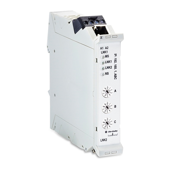
35 mm (1.38 in.) DIN rail mounting Status Indicators Optical communications bus (OLink) 2.0 EtherNet/IP address rotary switches Optical communications bus (OLink) 3.0 Two Ethernet network RJ45 connectors Removable terminal block 22.5 mm (0.89 in.) wide housing Rockwell Automation Publication 440R-UM009C-EN-P - July 2019... -
Page 10: Hardware/Software Compatibility
The interface and the applications that are described in this manual are Hardware/Software compatible with the following firmware revisions and software releases. Compatibility Contact your Rockwell Automation sales office or Allen-Bradley distributor if you need software or firmware updates to use this equipment. Product Firmware Revision/ Software Release 440R-ENETR interface 1.xx or later... -
Page 11: Understand The Producer/Consumer Model
A data connection to the interface is a grouping of data from one or more Guardmaster safety relays into one block of data that is sent over one connection at the same data rate. See the EtherNet/IP Design Considerations Reference Manual, publicationENET-RM002 for more information on connections. Rockwell Automation Publication 440R-UM009C-EN-P - July 2019... - Page 12 Chapter 1 Product Overview Notes: Rockwell Automation Publication 440R-UM009C-EN-P - July 2019...
-
Page 13: Relay Arrangement
2. Press down firmly to install the interface on the DIN rail. To remove your interface from the DIN rail, pry the DIN rail latch downwards until there is separation from the latch and the DIN rail. Rockwell Automation Publication 440R-UM009C-EN-P - July 2019... -
Page 14: Removable Terminal Block
Each terminal accommodates copper wire with size from 0.14…2.5 mm2 (26…14 AWG). Use copper wire that withstands 60…75 °C (140…167 °F). Each terminal can accommodate up to two wires. Terminal Torque Torque terminals to 0.4 N•m (4 lb•in). Rockwell Automation Publication 440R-UM009C-EN-P - July 2019... -
Page 15: Network Connections
Other helpful publications can be found in Additional Resources on page Rockwell Automation Publication 440R-UM009C-EN-P - July 2019... -
Page 16: Preventing Excessive Heat
Harmful contaminants or dirt could cause improper operation or damage to components. In extreme cases, the use air conditioning to help protect against heat buildup within the enclosure may be required. Rockwell Automation Publication 440R-UM009C-EN-P - July 2019... -
Page 17: Overview
001 to 254 assigns a fixed private IP address of 192.168.1.ABC. Figure 6 on page 18 shows an example with the ABC switches set to 163. Upon power-up, the ENETR interface assigns itself a fixed IP address of 192.168.1.163. Rockwell Automation Publication 440R-UM009C-EN-P - July 2019... -
Page 18: Use Bootp/Dhcp Server
7. This window does not appear if there is only one network connection available. For this example, the ‘USB2.0 to Fast Ethernet Adapter’ with IP address 192.168.2.10 is selected. Figure 7 - Select the BootP/DHCP Network Interface Rockwell Automation Publication 440R-UM009C-EN-P - July 2019... - Page 19 IP address. The Error and warnings section shows that it cannot service the request because you have not told it what address to use. Double-click the listing to open the New Entry window. Figure 9 - BootP/DHCP Commissioning Tool Rockwell Automation Publication 440R-UM009C-EN-P - July 2019...
- Page 20 Figure 12 - Right-click Relation Figure 13, the Errors and Warnings show that the Disable command was successful. Now, you can cycle power to the ENETR interface and this IP address remains configured. Rockwell Automation Publication 440R-UM009C-EN-P - July 2019...
- Page 21 IP address to the device. Click File and then Save As, as shown in Figure 14. Then, follow the instructions in each of the subsequent windows to save the file. Figure 14 - Save the Relation Rockwell Automation Publication 440R-UM009C-EN-P - July 2019...
-
Page 22: Use Third-Party Dhcp And Rslinx Software
6. Highlight the IP address that is the DHCP server. In this example, the DHCP server is 10.0.0.183. 7. Click OK. 8. Click Close to close the Configure Drives window. Figure 15 - Configure Driver Rockwell Automation Publication 440R-UM009C-EN-P - July 2019... - Page 23 14. Enter the desired IP address. In this example, we want 192.168.2.59. Leave the Network Mask as 255.255.255.0 and clear out all other fields. 15. Click OK. 16. Click Yes at the next prompt (not shown). Figure 17 - Reassign the IP Address Rockwell Automation Publication 440R-UM009C-EN-P - July 2019...
- Page 24 Figure 19, click Refresh. 23. The ENETR interface now has a fixed IP address of 192.168.2.59. You can right-click and delete the two connections that are not used. Figure 19 - Now Available Rockwell Automation Publication 440R-UM009C-EN-P - July 2019...
-
Page 25: Chapter 4 Download The Aop
Chapter Download and Install the Add-on Profile When using Rockwell Automation controllers, an Add-on Profile (AOP) can be added to the Controller Tags to facilitate the use of the performance characteristics of the GSR relays. To use the ENETR interface in a Logix Designer application, you must download and install the AOP. - Page 26 8. Accept the terms (not shown). 9. Use the Managed Download or Direct Download option (not shown) Figure 22 - Download Now The downloaded file is named 440RAdapter_Rel_Ver_2.00.51.zip, and shows the desired version (Figure 23). Rockwell Automation Publication 440R-UM009C-EN-P - July 2019...
-
Page 27: Install The Aop
Figure 24 - Run MPSetup The installation begins with the Profile Setup Wizard (Figure 25). 3. Click Next. Figure 25 - Profile Setup Wizard Figure 26 on page 28 shows the License Agreement. Rockwell Automation Publication 440R-UM009C-EN-P - July 2019... - Page 28 Figure 28 shows the module profiles to be installed. 7. Click Install to begin the installation. Figure 28 - Click Install to Begin Figure 29 on page 29 shows that the install was successful. Rockwell Automation Publication 440R-UM009C-EN-P - July 2019...
- Page 29 Figure 29 - Installation Succeeded Figure 30 shows the completion of the setup. 9. Check “Display RSLogix 5000...” to show the release notes after finishing. 10. Click Finish. Figure 30 - Finish The release notes are displayed. Rockwell Automation Publication 440R-UM009C-EN-P - July 2019...
- Page 30 Chapter 4 Download and Install the Add-on Profile Notes: Rockwell Automation Publication 440R-UM009C-EN-P - July 2019...
-
Page 31: Add Aop
3. Click the 440R-ENETR (the selection is now highlighted in blue). 4. Check the Close on Create box. 5. Click Create. Figure 32 - Select Module Type Upon creation, the New Module window appears, as shown in Figure Rockwell Automation Publication 440R-UM009C-EN-P - July 2019... - Page 32 • Disable Keying: The series letter and revision level are not used to determine if the module is correct. • Exact Match: Both the series letter and revision level must be correct to use the module. Figure 34 - Electronic Keying Rockwell Automation Publication 440R-UM009C-EN-P - July 2019...
-
Page 33: Add Relays To The Enetr Interface
Figure 35 - Module Definition 2. To select the upload path, click the ENETR interface (Figure 36). 3. Click OK. Figure 36 - Select Path The Upload Complete message (Figure 37 on page 34) confirms the operations. Rockwell Automation Publication 440R-UM009C-EN-P - July 2019... - Page 34 Figure 38 - Confirm the Configuration 9. Click Yes to confirm the change to the module definition (Figure 39). Figure 39 - Confirm Module Definition Change Figure 40 on page 35 shows the results of the setup. Rockwell Automation Publication 440R-UM009C-EN-P - July 2019...
- Page 35 11. To add the ENETR interface to the project, click OK. Figure 40 - Confirm Setup The ENETR interface is added to the project in the Controller Organizer (Figure 41). Figure 41 - ENETR Interface Added to the Controller Organizer Rockwell Automation Publication 440R-UM009C-EN-P - July 2019...
-
Page 36: Manual Method
The DG relay is added and located in Slot 1 (Figure 43). The GuardLink circuits are added with the default status as disabled; both inputs are configured as standard dual-channel. Figure 43 - DG Relay Added Rockwell Automation Publication 440R-UM009C-EN-P - July 2019... - Page 37 IMPORTANT Repeat steps 1…6 to add more relays and taps. The number and location of the relays and taps must be the same as the physical setup. 7. Click OK. Figure 45 - Rockwell Automation Publication 440R-UM009C-EN-P - July 2019...
- Page 38 Yes. Figure 46 - Change Module Definition The ENETR interface is added to the project in the Controller Organizer (Figure 47). Figure 47 - ENETR Interface Added to the Controller Organizer Rockwell Automation Publication 440R-UM009C-EN-P - July 2019...
-
Page 39: General Instructions For Faults
5. If the fault persists, replace the relay or tap. TIP The AOP in Studio 5000 sets the fault code style to Decimal. If a -1 appears as the fault code, change the style to Hexadecimal to get the value. Rockwell Automation Publication 440R-UM009C-EN-P - July 2019... -
Page 40: Enetr Input Tags
GLP, 5. EMD, 6. EM) and a FaultReset (or power cycle) is performed on an OLink 3.x device, the tags RelayxConnected behind the OLink 3.x device momentarily go to 0 and come back after the FaultReset (or power cycle). Rockwell Automation Publication 440R-UM009C-EN-P - July 2019... -
Page 41: Enetr Output Tags
Equivalent to cycling the power to a GuardLink tap and also to the device connected to the tap. Use this command to clear a fault on the tap or a fault on a device that is connected to the tap. Only one tap can be sent a fault reset command at a time. Rockwell Automation Publication 440R-UM009C-EN-P - July 2019... -
Page 42: Dual Guardlink (Dg) Tags
Reset Required Indication – Indicates whether the DG relay shows all monitored input conditions (both IN1 and IN2, as configured) are ON and the safety relay Output is OFF (0). 0 = No reset required. 1 = Waiting for reset signal at terminal X4. Rockwell Automation Publication 440R-UM009C-EN-P - July 2019... -
Page 43: Dg Fault Codes
67 (43) GuardLink-CH[1] no communication Check wiring - brown wire is connected to 24V, blue wire is connected to ground, white wire is connected to S32, and black wire is connected to S42. Rockwell Automation Publication 440R-UM009C-EN-P - July 2019... - Page 44 GuardLink-CH[0] Tap 27 comm error 284 (11C) GuardLink-CH[0] Tap 28 comm error 285 (11D) GuardLink-CH[0] Tap 29 comm error 286 (11E) GuardLink-CH[0] Tap 30 comm error 287 (11F) GuardLink-CH[0] Tap 31 comm error Rockwell Automation Publication 440R-UM009C-EN-P - July 2019...
- Page 45 320 (140) GuardLink-CH[1] Tap 32 comm error 512 (200) DG not configured. Configure the DG relay as stated in publication 440R-UM015. 513 (201) DG needs firmware update. Follow the general instructions for faults. Rockwell Automation Publication 440R-UM009C-EN-P - July 2019...
-
Page 46: Guardlink Tap Tags
SINT Diagnostic Code - See Table 6 on page 47 for more information. FaultCode SINT Fault Code - Indicates the fault code when the GuardLink circuit is faulted. See Table 7 on page Rockwell Automation Publication 440R-UM009C-EN-P - July 2019... -
Page 47: Guardlink Tap Diagnostic Codes
Evaluate supply voltage. Supply voltage must be 20.4…26.4V at all taps under all electrical load conditions. 64 (40) Device startup functional test Functionally test the monitored device. Cycle the device between safe and active state. 65 (41) Device fault functional test Rockwell Automation Publication 440R-UM009C-EN-P - July 2019... -
Page 48: Guardlink Tap Fault Codes
1 = No fault SafetyOutput BOOL Safety Output Status – Indicates whether the safety output channels are ON or OFF. 0 = The safety output channels are OFF. 1 = The safety input channels are ON. Rockwell Automation Publication 440R-UM009C-EN-P - July 2019... - Page 49 0 = No fault 1 = Fault ResetHeldOn BOOL Reset Held On Fault – Indicates the reset signal ON (1) for longer than the maximum time of 3000 ms. 0 = No fault 1 = Fault Rockwell Automation Publication 440R-UM009C-EN-P - July 2019...
-
Page 50: Di And Dis Fault Codes
Measure and adjust the voltage at terminal A1 to 20.4…26.4V under all electrical load conditions. 38 (26) Fault detected in the other Processor Follow the general instructions for faults. See General Instructions for Faults on page Rockwell Automation Publication 440R-UM009C-EN-P - July 2019... -
Page 51: Em Tags
NonRecoverableFault_B SINT Nonrecoverable Fault Processor B – Indicates that Safety Processor B has recorded a nonrecoverable fault. SeeTable 12 on page 53 a list of nonrecoverable fault codes. Rockwell Automation Publication 440R-UM009C-EN-P - July 2019... -
Page 52: Emd Tags
If the B1/B2 connection is remade while the safety output is ON, the same steps happen with the values reversed, and the PWR/Fault indicator changes to solid green. When the SafetyOutput tag is 0, the B1_B2_Setting_Change tag has a value of 0. 0 = Connection has not changed. 1 = Connection changed. Rockwell Automation Publication 440R-UM009C-EN-P - July 2019... -
Page 53: Em And Emd Fault Codes
Measure and adjust the voltage at terminal A1 to 20.4…26.4V under all electrical load conditions. 38 (26) Fault detected in the other Processor Follow the general instructions for faults. See General Instructions for Faults on page 42 (30) Capacitor short detected Rockwell Automation Publication 440R-UM009C-EN-P - July 2019... -
Page 54: Glp Tags
NonRecoverableFault_B SINT Nonrecoverable Fault Processor B – Indicates that Safety Processor B has recorded a nonrecoverable fault. See Table 14 on page 56 for a list of nonrecoverable fault codes. Rockwell Automation Publication 440R-UM009C-EN-P - July 2019... - Page 55 Unlock Request Held On Fault – Indicates the unlock request signal ON (1) for longer than the maximum time of 3000 ms. The fault is cleared when the signal is removed. 0 = No fault 1= Fault Rockwell Automation Publication 440R-UM009C-EN-P - July 2019...
-
Page 56: Glp Fault Codes
Proximity speed exceeds SL1 when safety gate is unlocked with Reduce the speed to below the SL1 setting. Cycle power. logic setting = 1 Processor A shows 00. Processor B shows FA. PWR/Fault indicator is flashing red 7X. Rockwell Automation Publication 440R-UM009C-EN-P - July 2019... -
Page 57: Glt Tags
NonRecoverableFault_B SINT Nonrecoverable Fault Processor B – Indicates that Safety Processor B has recorded a nonrecoverable fault. See Table 16 on page 58 a list of nonrecoverable fault codes. Rockwell Automation Publication 440R-UM009C-EN-P - July 2019... -
Page 58: Glt Fault Codes
07 (07) OSSD1 Check for short circuits at terminal 14 to 24V and 0V. Processor A shows 07. Processor B shows 07 (24V short). Processor A shows 07. Processor B shows 02 (0V short). Rockwell Automation Publication 440R-UM009C-EN-P - July 2019... - Page 59 Follow the general instructions for faults. See General Instructions for Faults on page 54 (36) Stack 55 (37) Wrong revision number (Processor B only) 56 (38) Array overflow 57 (39) 58 (40) Input not equal to other processor Rockwell Automation Publication 440R-UM009C-EN-P - July 2019...
-
Page 60: Si Tags
0 = No fault 1 = Fault ResetHeldOn BOOL Reset Held On Fault – Indicates the reset signal ON (1) for longer than the maximum time of 3000 ms. 0 = No fault 1 = Fault Rockwell Automation Publication 440R-UM009C-EN-P - July 2019... -
Page 61: Si Fault Codes
36 (24) Cross Fault at processor pins for safety outputs 37 (25) Fault of voltage reduction of the relay voltage 38 (26) The other Processor has a Fault only 39 (27)…255 (FF) Reserved Rockwell Automation Publication 440R-UM009C-EN-P - July 2019... - Page 62 Chapter 6 AOP Controller Tags Notes: Rockwell Automation Publication 440R-UM009C-EN-P - July 2019...
-
Page 63: Chapter 7 Indicator Location
Figure 48 - Diagnostic Status Indicators Module Status Link 1 Activity/Status Link 2 Activity/Status Network Status Table 19 on page 64 describes each of the indicators and recommended actions Indicator Description for each status. Rockwell Automation Publication 440R-UM009C-EN-P - July 2019... - Page 64 No action necessary. Flashing yellow Transmit or receive activity present on indicated port @ 10 Mbps. AOP: EthernetLinkxSts = 1 if ConnectionFaulted = 0. AOP: EthernetLinkxSts = 0 if ConnectionFaulted = 1. No action necessary. Rockwell Automation Publication 440R-UM009C-EN-P - July 2019...
-
Page 65: Chapter 8 Guardlink Commands
Rungs 11 and 12 provide an example of unlocking and locking a specific switch. In this case, we move a 4, which is the third tap, instead of a -1. Figure 49 - Unlock and Lock Commands Rockwell Automation Publication 440R-UM009C-EN-P - July 2019... -
Page 66: Lock And Unlock A Nonlocking Device
The unlock command for tap 4 must be cleared (set to 0), and a lock command must be sent to tap 4 to restore the GuardLink safety signal (Figure 51). Figure 51 - Lock Tap 4 Rockwell Automation Publication 440R-UM009C-EN-P - July 2019... -
Page 67: Fault Reset Command To All Guardlink Taps
The timer value is set to 3000 ms; enough time for the tap to execute its startup self-test. After timer is done, the FRC_0 output is unlatched, and the FRC_1 output is latched. The steps are repeated for each tap. Rockwell Automation Publication 440R-UM009C-EN-P - July 2019... - Page 68 Chapter 8 Studio 5000 Example Logix Code Figure 52 - Jump to Fault Reset Subroutine Rockwell Automation Publication 440R-UM009C-EN-P - July 2019...
-
Page 69: Guard Locking With Fault Reset Command
You can change the number of attempts and the delay that is allowed before determining the lock command does not work. The delay must be set for at least 200 ms. Rockwell Automation Publication 440R-UM009C-EN-P - July 2019... - Page 70 Chapter 8 Studio 5000 Example Logix Code Figure 53 - Logix Rockwell Automation Publication 440R-UM009C-EN-P - July 2019...
-
Page 71: Setup
Explicit communication is used when status information is requested from the ENETR interface or control signals are sent to the ENETR interface only when needed. This communication method is also used by non-Rockwell Automation controllers. The examples in this chapter show how to use the explicit communications when the AOP is not loaded into the Project. - Page 72 Figure 57 - Create Controller Tags Figure 58 on page 73 shows an example logic program. Add three rungs with the message block tags. When the program is running, toggle the HMI control to execute the message function. Rockwell Automation Publication 440R-UM009C-EN-P - July 2019...
- Page 73 IMPORTANT Repeat these steps for each of the message controls. Figure 59 - Communication Tab 19. Populate the five fields as shown in Figure 60 to read the ENETR interface configuration and click OK. Figure 60 - Config Message Configuration Rockwell Automation Publication 440R-UM009C-EN-P - July 2019...
-
Page 74: Configuration Data
DG relay as two inputs. Therefore, the Slot 1 GuardLink 1 taps are identified with bytes 6…37. Each GuardLink circuit occupies 32 bytes. IMPORTANT See Knowledgebase article 1087826 for additional configuration information: https://rockwellautomation.custhelp.com/app/answers/detail/a_id/1087826 Rockwell Automation Publication 440R-UM009C-EN-P - July 2019... - Page 75 Table 21 - Config IDs Type Name Cat. No. 440R-D22S2 440R-D22R2 440R-EM4R2 440R-EM4R2D Relay 440R-S12R2 440R-GL2S2P 440R-GL2S2P 440R-DG2R2T OSSD 5-pin 440S-SF5D OSSD 8-pin 440S-SF8D Taps EMSS 5-pin 440S-MF5D EMSS 8-pin 440S-MF8D Rockwell Automation Publication 440R-UM009C-EN-P - July 2019...
- Page 76 Chapter 9 Explicit Communication Notes: Rockwell Automation Publication 440R-UM009C-EN-P - July 2019...
-
Page 77: 440R-Enetr Specifications
• ±1 kV line-line (DM) and ±2 kV line-earth (CM) on power ports • ±2 kV line-earth (CM) on communications ports Conducted RF immunity IEC61000-4-6: • 10V rms with 1 kHz sine-wave 80% AM from 150 kHz...80 MHz Rockwell Automation Publication 440R-UM009C-EN-P - July 2019... - Page 78 Appendix A Specifications Notes: Rockwell Automation Publication 440R-UM009C-EN-P - July 2019...
-
Page 79: Certifications
– EN 61326-1; Meas./Control/Lab., Industrial Requirements – EN 61000-6-2; Industrial Immunity – EN 61000-6-4; Industrial Emissions – EN 61131-2; Programmable Controllers (Clause 8, Zone A & B) EtherNet/IP ODVA conformance tested to EtherNet/IP specifications Rockwell Automation Publication 440R-UM009C-EN-P - July 2019... - Page 80 Appendix B Regulatory Approvals Notes: Rockwell Automation Publication 440R-UM009C-EN-P - July 2019...
-
Page 81: Index
53 AOP 39 tag 52 enclosure consideration 15 ENETR add relays 33 Ethernet Industrial Protocol 10 EtherNet/IP 10 example Logix code 65 excessive heat 16 explicit communication 71 configuration data 74 setup 71 Rockwell Automation Publication 440R-UM009C-EN-P - July 2019... - Page 82 7 implicit primary tasks messaging 8 interface 8 information private IP address configuration 8 set 17 programming 8 producer input data model 11 real-time 8 protocol input tag 40 message-based 10 Rockwell Automation Publication 440R-UM009C-EN-P - July 2019...
- Page 83 DHCP/RSLinx 22 software releases 10 wire size 14 specifications 77 star 7 status indicator description 63 diagnostic 63 location 63 Studio 5000 example Logix code 65 support data connection 11 system power up 7 Rockwell Automation Publication 440R-UM009C-EN-P - July 2019...
- Page 84 Index Notes: Rockwell Automation Publication 440R-UM009C-EN-P - July 2019...
- Page 86 Rockwell Automation maintains current product environmental information on its website at http://www.rockwellautomation.com/rockwellautomation/about-us/sustainability-ethics/product-environmental-compliance.page. Allen-Bradley, ControlLogix, FactoryTalk, GuardLink, Guardmaster, Rockwell Automation, Rockwell Software, RSLinx, RSLogix, RSLogix 5000, and Studio 5000 are trademarks of Rockwell Automation, Inc. EtherNet/IP is a trademark of ODVA, Inc.
Need help?
Do you have a question about the Allen-Bradley Guardmaster 440R-ENETR and is the answer not in the manual?
Questions and answers