Table of Contents
Advertisement
Quick Links
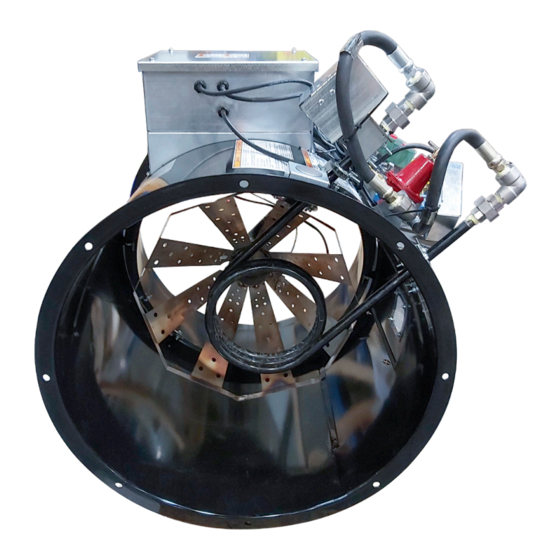
Axial Fan Heater
LP and NG-Fired Heater
Installation, Operation, and Parts Manual
Read this manual before using product. Failure to
follow instructions and safety precautions can
result in serious injury, death, or property
damage. Keep manual for future reference.
INSTALLATION AND WIRING MUST BE IN
ACCORDANCE WITH CEC, NEC, AND LOCAL
ELECTRICAL CODES
Part Number: GNA-2538 R0
Revised: March 2022
Original Instructions
Advertisement
Table of Contents
Troubleshooting

Related Manuals for AGI GGH-8371LO

Summary of Contents for AGI GGH-8371LO
- Page 1 Axial Fan Heater LP and NG-Fired Heater Installation, Operation, and Parts Manual INSTALLATION AND WIRING MUST BE IN ACCORDANCE WITH CEC, NEC, AND LOCAL ELECTRICAL CODES Read this manual before using product. Failure to Part Number: GNA-2538 R0 follow instructions and safety precautions can Revised: March 2022 result in serious injury, death, or property Original Instructions...
- Page 3 This product has been designed and manufactured to meet general engineering standards. Other local regulations may apply and must be followed by the operator. All personnel must be trained in the correct operational and safety procedures for this product. Use the sign-off sheet below to record initial and periodic reviews of this manual with all personnel.
- Page 4 AXIAL FAN HEATER – LP AND NG-FIRED HEATER GNA-2538 R0...
-
Page 5: Table Of Contents
AXIAL FAN HEATER – LP AND NG-FIRED HEATER CONTENTS 1. Introduction ............................7 1.1 Product Information........................7 1.2 Intended Use ..........................8 1.2.1 Misuse ........................8 2. Safety............................... 9 2.1 Safety Alert Symbol and Signal Words..................9 2.2 General Safety Information....................... 9 2.3 Heater Safety........................... - Page 6 AXIAL FAN HEATER – LP AND NG-FIRED HEATER 6.8 Access Door ..........................33 7. Troubleshooting............................ 34 7.1 General Troubleshooting......................34 7.2 Heater Troubleshooting Guide....................35 8. Appendix ............................... 38 8.1 General Drying Operation Information................... 38 8.2 FENWAL-Related Issues......................42 8.3 Electrical Schematics ....................... 46 8.4 Replacement Parts ........................
-
Page 7: Introduction
Keep this manual handy for frequent reference and to review with new personnel. A sign-off form is provided on the inside front cover for your convenience. If any information in this manual is not understood or if you need additional information, please contact AGI or your representative for assistance. -
Page 8: Intended Use
1. INTRODUCTION AXIAL FAN HEATER – LP AND NG-FIRED HEATER 1.2. Intended Use The axial heater is intended for use as listed below and described throughout this manual. Use in any other way is considered contrary to the intended use and is not covered by the warranty. The axial heater should be operated, maintained, serviced, and repaired only by persons who are familiar with its particular characteristics and understand the relevant safety procedures. -
Page 9: Safety
AXIAL FAN HEATER – LP AND NG-FIRED HEATER 2. SAFETY 2. Safety 2.1. Safety Alert Symbol and Signal Words This safety alert symbol indicates important safety messages in this manual. When you see this symbol, be alert to the possibility of injury or death, carefully read the message that follows, and inform others. -
Page 10: Heater Safety
2. SAFETY AXIAL FAN HEATER – LP AND NG-FIRED HEATER 2.3. Heater Safety Fire and explosion hazards, as well as carbon monoxide poisoning could occur if the heater is misused. To avoid serious injury or death: • Shut off and lock out or disconnect power and close valve at gas source before inspecting or servicing the heater, or when not in use. -
Page 11: Grain Bin Fires
AXIAL FAN HEATER – LP AND NG-FIRED HEATER 2. SAFETY 2.5. Grain Bin Fires To Prevent Fires: • Use the heater for its intended use only. • Ventilate, purge all contaminates, and allow burner, and drying areas to cool inside the heater, in the heater area and the grain bin before any persons enter these areas. -
Page 12: Drives And Lockout/Tagout Safety
2. SAFETY AXIAL FAN HEATER – LP AND NG-FIRED HEATER 2.6. Drives and Lockout/Tagout Safety Inspect the power source(s) before using and know how to shut down in an emergency. Whenever you service or adjust your equipment, make sure you shut down your power WARNING source and gas supply and follow lockout and tagout procedures to prevent inadvertent start-up and hazardous energy release. -
Page 13: Decal Installation/Replacement
AXIAL FAN HEATER – LP AND NG-FIRED HEATER 2. SAFETY • Replace safety decals that are missing or have become illegible. See decal location figures that follow. • Replaced parts must display the same decal(s) as the original part. • Replacement safety decals are available free of charge from your distributor, dealer, or factory as applicable. 2.9.1 Decal Installation/Replacement 1. - Page 14 2. SAFETY AXIAL FAN HEATER – LP AND NG-FIRED HEATER Table 1. Safety Decals Part Number Description 601-1995 WARNING (Control panel cover, outside) ELECTROCUTION HAZARD To prevent serious injury or death: • Only qualified personnel should service electrical components. • Disconnect and lockout power before inspecting or servicing unit.
- Page 15 AXIAL FAN HEATER – LP AND NG-FIRED HEATER 2. SAFETY Table 1 Safety Decals (continued) Part Number Description 601-3582 WARNING AVERTISSEMENT (Heater housing) If the information in the manual is not followed exactly, a fire Si les informations données dans le mode d’emploi ne sont pas respectées à...
- Page 16 à la source d’alimentation en gaz avant If the operator manual, guards, or safety d’inspecter ou d’entretenir l’appareil. Consulter le manuel decals are missing or damaged, contact AGI d’utilisation pour plus d’informations. at +1-800-565-2840 or www.grainguard.com Si le manuel d’utilisation, les protecteurs ou les...
-
Page 17: Features
Read this section to familiarize yourself with the basic component names and functions of the axial heater. 3.1. Axial Heater Note AGI Axial Heaters are sized according to the axial fan’s power source and the motor HP rating. CONTROL BOX THERMOSTAT ASSEMBLY... -
Page 18: Control Box Assembly
SWITCH 3A FUSE INDICATOR 1.5A FUSE 3. FEATURES AXIAL FAN HEATER – LP AND NG-FIRED HEATER LIGHT 3.2. Control Box Assembly Important The power “IN” to the heater control box comes from the axial fan - this must be wired such that there is no power to the heater unless the fan is running. -
Page 19: Installation
Inspect the axial heater and accessories on receipt to ensure that all items have arrived and that none are damaged. Report missing or damaged parts immediately to ensure that proper credit is received from AGI or your distributor/dealer, and to ensure that any missing parts can be shipped quickly to avoid holding up the installation. -
Page 20: Electrical Connection
• The heater power source must be electrically interlocked to the fan to ensure operation only when the fan is running. • AGI recommends that all fan/heaters are connected to a ground rod. Check previously installed units for proper grounding. -
Page 21: Disconnect
Canadian Electric Code, Part I, CSA C22.1. 4.4.2 Grounding • AGI recommends that fan and heater be connected to a ground rod that is no further than 8 feet away. • The ground rod should be connected with a minimum 6 AWG solid, bare copper wire. -
Page 22: Fuel Supply
• At the owner’s discretion, a first stage liquid regulator may be included. It must be capable of 75 gph at 100 psi under flow. This item is not supplied by AGI. • Storage tanks must be located at least 25’ (7,620 mm) from all structures, depending on local codes. Check with the gas supplier for code specifications. - Page 23 AXIAL FAN HEATER – LP AND NG-FIRED HEATER 4. INSTALLATION Important Required: Make sure the supply tank has a properly sized relief valve, a vapor tap, and a liquid tap with a rapid flow shutoff valve to stop the flow of propane in case of a break in the gas line. The liquid tap should have a rapid flow shutoff valve to stop the flow of propane if a fuel line breaks.
- Page 24 4. INSTALLATION AXIAL FAN HEATER – LP AND NG-FIRED HEATER Table 3. Line Sizing Chart — Liquid Propane (LP) Gas Liquid — Copper Tubing Line Length Copper Tubing — Type K Liquid Propane Flow Rate Outside Diameter 3/8” (9.5 mm) 1/2”...
-
Page 25: Install The Heater
Important • Use the appropriate adapter plates to connect fans and heaters to transitions. AGI can provide adapter plates - contact your dealer. • Do not weld on the heater, fan, or transition flanges, welding distortions can cause vibrations. -
Page 26: Connect The Gas Supply
4. INSTALLATION AXIAL FAN HEATER – LP AND NG-FIRED HEATER 4.7. Connect the Gas Supply This procedure describes how to connect propane or natural gas to the heater, test for piping system pressure, and test for gas leaks. Connecting the Gas Hose 1. -
Page 27: Operation
AXIAL FAN HEATER – LP AND NG-FIRED HEATER 5. OPERATION 5. Operation Before continuing, ensure you have completely read and understood this manual’s Safety section, in addition to the safety information in the section(s) below. 5.1. Operation Safety • Ensure the heater is connected to the appropriate gas supply and the gas selector valve is properly set. -
Page 28: Start-Up And Operation
5.3.1 Liquid Propane Startup AGI liquid propane heaters require vapor for startup. Important A heater equipped with a vaporizer coil must use liquid propane. Vapor propane is only used for initial warm-up. - Page 29 AXIAL FAN HEATER – LP AND NG-FIRED HEATER 5. OPERATION 5. When ignition has been obtained, allow the burner to run for about 3 minutes. Adjust the gas pressure regularly to desired temperature rise. 6. After the burner ignites, adjust the thermostat to desired temperature. •...
-
Page 30: Shutdown
5. OPERATION AXIAL FAN HEATER – LP AND NG-FIRED HEATER 5.4. Shutdown 1. Close the gas shut off valve. 2. Allow heater flame to burn out. This drains all gas from supply. 3. Move the toggle switch to the OFF position. 5.5. -
Page 31: Maintenance
• After maintenance is complete, replace all guards, service doors, and/or covers. • Use only genuine AGI replacement parts or equivalent. Use of unauthorized parts will void warranty. If in doubt, contact AGI or your local dealer. -
Page 32: Visually Inspect The Axial Heater
6. MAINTENANCE AXIAL FAN HEATER – LP AND NG-FIRED HEATER 6.3. Visually Inspect the Axial Heater Check the following during a visual inspection: 1. Ensure all guards are in place and in good working order. 2. Examine the axial heater for damage or unusual wear. 3. -
Page 33: Pressure Regulator Maintenance
• Tampering with the regulator voids the warranty. • Regulator replacement must be performed at the factory or be performed by a qualified gas technician approved by AGI. Death or serious injury due to fire or explosion could result from an improperly connected pressure regulator. -
Page 34: Troubleshooting
You may also contact an AGI product specialist at 1–800–565–2840. Before you contact them, please have this operation manual and the serial number from your machine ready. -
Page 35: Heater Troubleshooting Guide
AXIAL FAN HEATER – LP AND NG-FIRED HEATER 7. TROUBLESHOOTING 7.2. Heater Troubleshooting Guide Never check for a spark without first shutting off the fuel supply and purging all fuel from the system. Purge the fuel system by shutting off the fuel supply, starting the fan, and cycling the burner ignition sequence 2 to 3 times. - Page 36 7. TROUBLESHOOTING AXIAL FAN HEATER – LP AND NG-FIRED HEATER Table 5 Problems, Causes and Solutions (continued) Problem Check Possible Cause Solution Flame tripping hi Flame too hot Reduce gas pressure Limit Vaporizer tripping hi Vaporizer coil too hot Adjust location to run cooler limit Reduce gas pressure Ignitor gap...
- Page 37 AXIAL FAN HEATER – LP AND NG-FIRED HEATER 7. TROUBLESHOOTING Table 5 Problems, Causes and Solutions (continued) Problem Check Possible Cause Solution Fittings/Valves Fuel Supply Burner firing rate Check all fittings to ensure that exceeds vaporization frosting is not present on fittings if frosting up (liquid rate so, let fittings/valves thaw and...
-
Page 38: Appendix
• All heater models include an ON/OFF switch and thermostat to control on-off cycling of heater. • AGI recommends that a thermometer be mounted near the burner control probe under the bin to ensure that the burner controls are operating at the desired setting. - Page 39 NOT recommended. Excessive temperatures can lead to uneven drying, scorched product, or fire. • AGI also recommends that a thermometer be mounted near the burner control probe under the bin to help ensure that burner controls are operating at the desired setting.
- Page 40 8. APPENDIX AXIAL FAN HEATER – LP AND NG-FIRED HEATER Table 7. BTU'S per Gauge Pressure (PSI) - Propane Models (Approximate) Model Gas Manifold Pressure -PSI Orifice dia" 0.14 308900 436800 534900 617800 690600 756600 817100 873600 926600 976700 24" 630300 891400 1091700...
- Page 41 AXIAL FAN HEATER – LP AND NG-FIRED HEATER 8. APPENDIX Table 9. BTU'S per Gauge Pressure (PSI) - Natural Gas Models (Approximate) Model Gas Manifold Pressure -PSI Orifice dia" 0.219 380832 538578 659620 761664 851566 932844 1007587 1077156 24" 0.313 777918 1100142 1347394 1555837 1739478 1905503 2058179 2200285 0.219...
-
Page 42: Fenwal-Related Issues
8. APPENDIX AXIAL FAN HEATER – LP AND NG-FIRED HEATER 8.2. FENWAL-Related Issues Input Polarity If the system shuts down after the ignition trial period even though a spark is present and the gas valves are open, measure the voltages at L1 and L2 with respect to ground. The voltage at terminal (L1) should be 120 VAC;... - Page 43 AXIAL FAN HEATER – LP AND NG-FIRED HEATER 8. APPENDIX Sequence of Operation / Flame Recovery / Safety Lockout • Start-Up - Heat Mode: 1. When a call for heat is received from the thermostat supplying 120VAC to L1, the control will reset, perform a self-check routine, flash the contol board diagnostic LED and begin a pre-purge delay.
- Page 44 8. APPENDIX AXIAL FAN HEATER – LP AND NG-FIRED HEATER 3. FLAME FAILURE-RECYCLE MODE – With the “Recycle After Loss of Flame” option, upon loss of flame, the solenoid gas valve is de-energized and the control proceeds to inter-purge before attempting to relight the flame. –...
- Page 45 AXIAL FAN HEATER – LP AND NG-FIRED HEATER 8. APPENDIX Fenwal Troubleshooting Table 11. Troubleshooting Guide Symptom Recommended Actions Miswired No 120 VAC at L1 Control does not start Fuse or circuit breaker fault Faulty control, check LED for fault codes Miswired Faulty thermostat, no voltage at terminal L1 Thermostat on —...
-
Page 46: Electrical Schematics
8. APPENDIX AXIAL FAN HEATER – LP AND NG-FIRED HEATER 8.3. Electrical Schematics Important When installing new wires, always replace wires with original type and/or an equivalent wire type. GNA-2538 R0... -
Page 47: Replacement Parts
3A FUSE INDICATOR 1.5A FUSE LIGHT AXIAL FAN HEATER – LP AND NG-FIRED HEATER 8. APPENDIX 8.4. Replacement Parts Figure 4. Model GNH-7508 Control Box Table 13. Model GNH-7508 Control Box Parts ITEM PART NO DESCRIPTION QTY. 507-1293 BLACK SWITCH BOOT 507-1294 TOGGLE SWITCH ON/OFF 250V 1 POLE 508-1118... - Page 48 8. APPENDIX AXIAL FAN HEATER – LP AND NG-FIRED HEATER Figure 5. Model GGH-8361LO GGH-8361LO CKET ITEM PART NO DESCRIPTION QTY. 202-2878 HTR VAPORIZER COIL AX 23" BLK 307-1231 CAPSCREW, 1/4 X 1" GR5 ZINC NC 307-3238 BOLT 3/8-16 X 4.75" ZINC PLTD 309-1413 NUT 7/8"...
- Page 49 AXIAL FAN HEATER – LP AND NG-FIRED HEATER 8. APPENDIX GUK-2523 HTR AX24 ORIFICE PLUG .20" 529-4804 FITTING ELBOW 90° SS 1/2'' X 1/2'' SCH80 529-4816 FITTING NIPPLE CLOSE SS 1/2'' SCH80 529-4832 FITTING UNION SS 1/2'' SCH80 GNH-7508 CONTROL BOX HTR DSH GNK-2535 HTR AX24/28 AIRTUBE GSK-5288...
- Page 50 8. APPENDIX AXIAL FAN HEATER – LP AND NG-FIRED HEATER Figure 6. Model GGH-8361NO GGH-8361NO ITEM PART NO DESCRIPTION QTY. 307-1231 CAPSCREW, 1/4 X 1" GR5 ZINC NC 307-3238 BOLT 3/8-16 X 4.75" ZINC PLTD 309-1413 NUT 7/8" HEX 1/4" NPT BRASS 309-2402 NUTSERT, 1/4"...
- Page 51 AXIAL FAN HEATER – LP AND NG-FIRED HEATER 8. APPENDIX GNK-2535 HTR AX24/28 AIRTUBE GZK-2507 HTR AX24/28 DEFLECTOR CONE BRACKET GZK-7540 HTR AX24 CONTROL BOX MOUNT ASSEM GZK-2522 HTR AX24 DEFLECTOR RING GXK-7541 HTR AX24 ACCESS DOOR ASSEMBLY GSK-5288 HTR AX24 ORIFICE PIPE WELDMENT GUK-5284 HTR AX24/28 BURNER WELDMENT GUK-7542...
- Page 52 8. APPENDIX AXIAL FAN HEATER – LP AND NG-FIRED HEATER Figure 7. Model GGH-8362LO GGH-8362LO ITEM PART NO DESCRIPTION 202-2878 HTR VAPORIZER COIL AX 23" BLK 307-1231 CAPSCREW, 1/4 X 1" GR5 ZINC NC 307-3237 BOLT 3/8-16 X 7" ZINC PLTD 309-1413 NUT 7/8"...
- Page 53 AXIAL FAN HEATER – LP AND NG-FIRED HEATER 8. APPENDIX 529-4832 FITTING UNION SS 1/2'' SCH80 GNH-7508 CONTROL BOX HTR DSH GNK-2535 HTR AX24/28 AIRTUBE GSL-5290 HTR AX28 ORIFICE PIPE WELDMENT GXL-7544 HTR AX28 ACCESS DOOR ASSEMBLY GUK-5284 HTR AX24/28 BURNER WELDMENT GUK-7539 HTR VALVE TRAIN LP LIQUID GUL-2530...
- Page 54 8. APPENDIX AXIAL FAN HEATER – LP AND NG-FIRED HEATER Figure 8. Model GGH-8362NO GGH-8362NO ITEM PART NO DESCRIPTION QTY. 307-1231 CAPSCREW, 1/4 X 1" GR5 ZINC NC 307-3237 BOLT 3/8-16 X 7" ZINC PLTD 309-1413 NUT 7/8" HEX 1/4" NPT BRASS 309-2402 NUTSERT, 1/4"...
- Page 55 AXIAL FAN HEATER – LP AND NG-FIRED HEATER 8. APPENDIX GUK-7548 HTR AX24/28 VALVE TRAIN NG GUL-2592 HTR AX28 ORIFICE PLUG .375" GXL-7544 HTR AX28 ACCESS DOOR ASSEMBLY GSL-5290 HTR AX28 ORIFICE PIPE WELDMENT GXL-5289 HTR AX28 HOUSING WELDMENT GZB-3671 ROUND COPPER TUBING RETAINER GZK-2507 HTR AX24/28 DEFLECTOR CONE BRACKET...
- Page 56 8. APPENDIX AXIAL FAN HEATER – LP AND NG-FIRED HEATER Figure 9. Model GUK-7539 GUK-7539 Table 14. Model GUK-7539 Parts ITEM PART NO DESCRIPTION QTY. 527-2617 STRAINER LP 1/2" 40 MESH 600PSI 527-4837 RELIEF VALVE CAP 1/4'' 527-4839 RELIEF VALVE POP UP 1/4" 450PSI 528-4849 SOLEN VLV 1/2'' 120V W/DIN 529-2997...
- Page 57 AXIAL FAN HEATER – LP AND NG-FIRED HEATER 8. APPENDIX Figure 10. Model GUK-7542 GUK-7542 QTY. ITEM PART NO DESCRIPTION QTY. 527-2605 1/2X1/2 HI PRESS REGULATOR 3-30PSI 527-4836 RELIEF VALVE POP UP 1/4'' 26PSI 527-4837 RELIEF VALVE CAP 1/4'' 528-4847 SOLEN VLV 3/4'' 120V W/DIN 529-2996 FITTING 1/4"...
- Page 58 8. APPENDIX AXIAL FAN HEATER – LP AND NG-FIRED HEATER Figure 11. Model GUK-7545 QTY. 3-30PSI 26PSI GUL-7545 2'' SCH80 1 4'' SCH40 1 ' SCH40 ' SCH40 SCH80 SCH40 VALVE 155" T HTR DMENT 25" ITEM PART NO DESCRIPTION QTY.
- Page 59 AXIAL FAN HEATER – LP AND NG-FIRED HEATER 8. APPENDIX Figure 12. Model GUK-7548 GUK-7548 Table 15. Model GUK-7548 Parts ITEM PART NO DESCRIPTION QTY. 527-2605 1/2X1/2 HI PRESS REGULATOR 3-30PSI 527-4836 RELIEF VALVE POP UP 1/4'' 26PSI 527-4837 RELIEF VALVE CAP 1/4'' 528-4847 SOLEN VLV 3/4'' 120V W/DIN 529-4804...
-
Page 60: Warranty
AXIAL FAN HEATER – LP AND NG-FIRED HEATER 9. Warranty Except as expressly provided in this agreement, AGI (hereinafter called the Manufacturer) excludes all express or implied warranties, conditions, and obligations of the Manufacturer, whether statutory or otherwise, concerning the quality of the units or their fitness for any purpose. - Page 61 AXIAL FAN HEATER – LP AND NG-FIRED HEATER 9. WARRANTY GNA-2538 R0...
- Page 62 AGI is a leading provider of equipment solutions for agriculture bulk commodities including seed, fertilizer, grain, and feed systems with a growing platform in providing equipment and solutions for food processing facilities. AGI has manufacturing facilities in Canada, the United States, the United Kingdom, Brazil, South Africa, India and Italy and distributes its products globally.
Need help?
Do you have a question about the GGH-8371LO and is the answer not in the manual?
Questions and answers