Table of Contents
Advertisement
Condensing Combi Boiler
Service Manual
Getting Service
If your boiler requires service, you have several options for getting service:
Contact an official Technical Assistance Service (TAS) at 0844 332 2323 or go to the website
●
(www.navien.co.uk).
For warranty service, always contact an official Technical Assistance Service (TAS) first.
Contact the technician or professional who installed your boiler.
●
Contact a Gas Safe Registered engineer.
●
When contacting an official Technical Assistance Service (TAS), please have the following information
available:
Model number
●
Serial number
●
Date purchased
●
Installation location and type
●
Error code, if any appears on the front panel display
●
Navien LTD
Building 2, Guildford Business Park, Guildford, GU2 8XH
TEL 0844 332 2323 www.navien.co.uk
Version: 1.0(September, 2022)
Advertisement
Table of Contents
Troubleshooting

Related Manuals for Navien NCB300-28K


Summary of Contents for Navien NCB300-28K
- Page 1 Serial number ● Date purchased ● Installation location and type ● Error code, if any appears on the front panel display ● Version: 1.0(September, 2022) Navien LTD Building 2, Guildford Business Park, Guildford, GU2 8XH TEL 0844 332 2323 www.navien.co.uk...
- Page 2 Condensing Combi Boiler Service Manual Model NCB300-28K NCB300-37K NCB300-41K Keep this manual near this boiler for future reference whenever maintenance or service is required. WARNING If the information in these instructions is not followed exactly, a fire or explosion may result, causing property damage or personal injury.
-
Page 4: Error
Revisions Version Description of changes Date 1.00 First issue September. 7, 2022 Revisions... -
Page 5: Table Of Contents
Contents 1. Safety Information 5. Troubleshooting 5.1 Error Code Classification 2. Product Information 5.2 Error Code List and Actions 2.1 Product Information 5.2.1 Error 001 5.2.2 Error 003 2.2 Components 5.2.3 Error 004 5.2.4 Error 012 3. Technical Data 5.2.5 Error 016 5.2.6 Error 030 3.1 General Specifications 5.2.7 Error 031... - Page 6 Navien. When the product is installed in a new rules, laws or building codes. installation, the warranty period will start from the date the end- Product purchased through the internet, other e-commerce ●...
- Page 7 Abbreviations and Definitions Abbreviation Definition NCB300 General name for NCB300-28K, NCB300-37K, NCB300-41K products Natural Gas Propane Gas Air Pressure Air Pressure Sensor Domestic Hot Water Fan Motor GARC Gas Air Ratio Control Litre Per Minute Main Gas Valve Revolutions per Minute...
-
Page 8: Safety Information
1. Safety Information The following safety symbols are used in this manual. Read and DANGER follow all safety instructions in this manual precisely to avoid unsafe operating conditions, fire, explosion, property damage or personal injury. DANGER Indicates an imminently hazardous situation which, if not avoided, could result in severe injury or death. - Page 9 WARNING WARNING This appliance can be used by children aged from 8 years and above and persons with reduced physical, sensory or mental capabilities or lack of experience and knowledge if they have been given supervision or instruction concerning use of the appliance in a safe way and understand the hazards involved.
- Page 10 CAUTION DANGER Do not turn on the boiler unless ● the water and gas supplies are fully opened. Doing so may damage the boiler. Do not turn on the water if the cold ● BURN water supply shut-off valve is closed. Doing so may damage the boiler.
- Page 11 The Codes of good practice and regulations refer to the latest versions of the same. Navien ensures that this product contains no harmful The installation must also comply with the following European substances and that no harmful materials have been used in its Standards: manufacture.
-
Page 12: Product Information
Depending on the heat capacity, two models are available with different ratings: 28 kW, 37 kW, and 41 kW. Model Maximum Space Heating Input Maximum DHW INPUT NCB300-28K 24.7 kW 28.0 kW NCB300-37K 26.8 kW 37.0 kW... -
Page 13: Components
2.2 Components The following diagram shows the key components of the boiler. Component assembly diagrams and particular parts lists are included in the Appendices. Fan & Motor Ignitor & Flame Rod Front Panel Gas Valve Circulation Pump NCB300-28K Product Information... - Page 14 Mixing Chamber Single Venturi Primary Heat Exchanger Secondary Heat Exchanger Gas Valve 3-Way Valve Return Adapter Filter Assembly Pressure Relief Valve Central Heating Supply Central Heating Return DHW Outlet DHW Inlet NCB300-28K Product Information...
- Page 15 Fan & Motor Ignitor & Flame Rod Front Panel Gas Valve Circulation Pump NCB300-37K NCB300-41K Product Information...
- Page 16 Mixing Chamber Single Venturi Primary Heat Exchanger Secondary Heat Exchanger Gas Valve 3-Way Valve Return Adapter Filter Assembly Pressure Relief Valve Central Heating Supply Central Heating Return DHW Outlet DHW Inlet NCB300-37K NCB300-41K Product Information...
-
Page 17: Technical Data
3. Technical Data 3.1 General Specifications The table below lists the boiler’s general specifications. NCB300-28K NCB300-37K NCB300-41K Specifications Unit Heat input range 24.7/4.3 26.8/4.6 26.8/4.6 DHW heat input range 28.0/4.3 37.0/4.6 41.0/4.6 Heat output range @ 80/60°C 24.0/4.2 26.0/4.5 26.0/4.5 DHW output range 28.0/4.3... - Page 18 NCB300-28K NCB300-37K NCB300-41K Specifications Unit Coaxial Ø60/100 and Ø80/ Flue exhaust/Air intake system diameters 125–Dual duct Ø80/80 Max. gas pipe pressure drop Max. horizontal coaxial length Ø60/100 Max. vertical coaxial length Ø60/100 Equivalent elbow length @ 90° Ø60/100 Equivalent elbow length @ 45° Ø60/100 Max.
-
Page 19: Dimensions
Cold water inlet (DHW) 15 mm Central heating return 22 mm Overhead View Bottom View 197.5 mm 170.6 mm 170.6 mm 56 mm 56 mm 65 mm 65 mm 126 mm 126 mm 65 mm 65 mm NCB300-28K NCB300-37K NCB300-41K Technical Data... -
Page 20: System Details
4. System Details 4.1 Setting the DIP Switches DIP SW2 Switch Function Setting CAUTION Reserve Do not remove the front cover unless the power to the Reserve boiler is turned off or disconnected. Failure to do so may Reserve result in electric shock. 5&6 Country The boiler has 2 sets of DIP switches on the main circuit board... -
Page 21: Measuring The Incoming Gas Pressure
4.2 Measuring the Incoming Gas Pressure To measure the inlet gas pressure: 1. Shut off the manual gas valve on the gas supply line pipe. WARNING The boiler cannot function properly without sufficient inlet gas pressure. Measuring the inlet gas pressure should be performed by a licensed professional only. -
Page 22: Gas Conversion
T15 Hexalobular Wrench ● Combustion Analyser or Dual Port Manometer ● Gas Leak Detector ● Included Items: Gas Orifice (refer to below table) ● Model NCB300-28K Ø5.95 Ø4.75 NCB300-37K Ø6.35 Ø5.05 NCB300-41K Ø6.35 Ø5.05 Table 1. Orifice Size Gas Pressure and Conversion Kit Number Labels ●... - Page 23 Procedure: 7. Remove the front panel assembly. 1. Turn off both gas and water supply to the boiler. 2. Unfasten the two latches (at the top) and remove two screws (at the bottom) to remove the front cover to gain access to the internal components.
- Page 24 ● Remove two pressure could result in damage to the valve, causing screws here potential severe personal injury or substantial property damage. Navien NCB300 boilers are shipped ready to fire natural gas only. Location A: Loosen the hex nut here Inner Packing Figure 3.
- Page 25 Replace the old Orifice piece with the new part for use with LP gas. Ensure that the Orifice is properly seated inside the port before proceeding to the next step. 11. Replace the gas inlet pipe to its original position and use all screws to secure all connections.
- Page 26 Gas type [20 mbar] [37 mbar] Model Output Consumption Gas flow Gas flow Load Kcal/h Max. 20,640 24.0 24.7 2.645 0.252 NCB300-28K Min. 3,700 1.775 0.169 Max. 22,360 26.0 26.8 2.870 0.273 NCB300-37K NCB300-41K Min. 3,870 1.944 0.185...
-
Page 27: Using The Front Panel
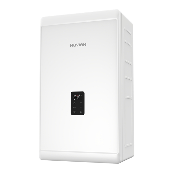
4.4 Using the Front Panel The front panel allows you to adjust the temperature and view the operating status or error codes. Remove the protective sheet from the front panel before using it. 4.4.1 Icons and Digital Display The icons and digital display on the front panel provide important information required for the boiler’s operation. -
Page 28: Buttons
4.4.2 Buttons Using the buttons on the front panel, you can turn on or off the boiler, monitor the current operation status, and set the values required for the boiler’s operation, such as central heating and DHW supply temperatures. Refer to the following table for detailed information. Menu button Eco button Access to the Main menu screen. -
Page 29: Turning The Boiler On Or Off
4.4.3 Turning the Boiler On or Off 2. Press the Plus button ( ) or the Minus button ( ) until desired temperature appears on the display. You can adjust the temperature while the display is flashing. To turn the boiler on or off, press the Power button ( Once the display stops flashing, the temperature setting is stored. -
Page 30: Resetting The Boiler
4.4.4.2 Adjusting the DHW Temperature 4.4.5 Resetting the Boiler If an error message appears, you can try resetting the boiler to resolve the problem. To reset the boiler, press the Power button WARNING Before adjusting the water temperature, carefully read “To prevent burns:”... -
Page 31: Accessing Basic Menu Items
4.4.6 Accessing Basic Menu Items 4.4.6.2 Setting the Central Heating Temperature To set the boiler’s central heating operation, press the Menu In the Main Menu screen, you can view the boiler’s operating button ( conditions, configure the central heating and DHW temperatures, and review error history. - Page 32 4.4.6.5 Viewing Error History 4.4.6.6 Viewing Service Information To view the error history, press the Info button ( ) and the ECO To view the miscellaneous system information, press the Info button ( ) simultaneously for 5 seconds. button ( ) for 5 seconds.
-
Page 33: Accessing Advanced Menu Items
4.4.7 Accessing Advanced Menu Items Item Description G. Model Capacity Model capacity (kW) 4.4.7.1 Setting the Operation Parameters Fuel Type H. Gas Type (LNG G20/LPG G30/LPG G31) To Set the boiler’s operation parameters, press the ECO button ) and Menu button ( ) simultaneously 5 seconds, and I. - Page 34 ● Default: 3°C ● Set the central heating Set the heat demand control minimum heat capacity limit. type for Navien thermostat, S. CH Heat Demand Setting range: Central heating ● Panel, Open Therm, CH minimum capacity (%) – Thermostat, and Switched Live.
- Page 35 4.4.7.2 Diagnosing the Boiler System Item Description To Set the boiler’s operation parameters, press the ECO button Test the 3 way valve operation. ) and Menu button ( ) simultaneously 5 seconds, and The 3 way valve is turned on ●...
-
Page 36: Wiring Diagram
4.5 Wiring Diagram BLDC FAN Valve Outdoor Sensor 8 6 4 2 7 5 3 1 DHW_INPUT CN12 5 4 4 CN14 PUMP WAV V/V 3WAY-Valve WAV,MIX V/V CN11 applies to NCB300 Combi MIX V/V PIN1 CN10 CN13 Dip s/w 2 3 4 2 3 4 6 7 8... -
Page 37: Ladder Diagram
4.6 Ladder Diagram LIVE NEUTRAL 240 VAC FILTER Relay 1 Igniter Relay 2 Circulation Pump Relay 3 3WAY DC15V Transformer BLDC-FAN Primary Speed Control NCB300 Combi Series Secondary Only Water Adjustment 130V Valve Mixing DC30V Valve Trans DC24V DC 9V DC12V Flow Control Flow Control... -
Page 38: Key Component Descriptions
4.7 Key Component Descriptions 4.7.1 PCB Item Description Function Controls each component and monitors the overall performance of the unit. Fault PCB malfunction A system component may not operate and generate an error code. In most PCB failures, the boiler will not Symptoms operate until the fault is resolved. -
Page 39: High Temperature Limit Switch
4.7.2 High Temperature Limit Switch Item Description 1. Overheat prevention switch. Function 2. If the switch detects extremely high temperature, the boiler will automatically trip and shut down. 3. Excessive high water temperatures (> 105°C) in the heat exchanger will activate the high limit switch. Fault Unable to detect high water temperature conditions if the switch malfunctions. -
Page 40: Thermistor
4.7.3 Thermistor Item Description Function Measure hot and cold water temperature at the boiler’s space heating outlet and inlet connections. Fault Inaccurate water temperatures from inside the boiler. 1. If a thermistor fails, an error code is displayed before the boiler operates. Symptoms 2. -
Page 41: Fan Motor
4.7.4 Fan Motor Item Description Supplies combustion air for the burner and purges exhaust flue gas. Function To maintain gas input over long flue runs, the fan use APS to provide ideal combustion levels. 1. Fan speed failure: When fan speed is approximately 0 rpm. Fault 2. -
Page 42: Flame Rod Assembly
4.7.5 Flame Rod Assembly Item Description Function Repeatedly discharges a high voltage spark at the main burner until the gas ignites. 1. Unable to ignite the gas. Fault 2. Results in multiple unsuccessful ignition attempts. 1. The boiler does not ignite and error code E003 or E004 is displayed. Symptoms 2. -
Page 43: Ignition Transformer
4.7.6 Ignition Transformer Item Description Function Provides voltage for the igniter for gas ignition purposes. 1. The igniter is unable to ignite the gas. Fault 2. Results in multiple unsuccessful ignition attempts to. 1. The boiler does not ignite and error code E003 or E004 is displayed. Symptoms 2. -
Page 44: Main Gas Valve
4.7.7 Main Gas Valve Item Description 1. Controls the amount of gas supplied to the burner based on fan speed. Function 2. When the unit experiences abnormal combustion, it automatically shuts off the gas supply to prevent unsafe situations. Fault Unable to open / close 1. -
Page 45: Burner
4.7.8 Burner Item Description 1. Pre-mixes air and gas to reduce emissions and increase efficiency. Function 2. The burner produces the optimum air/gas mixture required to produce the correct level of heat during combustion. 1. Unable to initiate or sustain combustion. Fault 2. -
Page 46: Flow Sensor
4.7.9 Flow Sensor Item Description Function To detect water flow in LPM (litres per minute) to provide a steady hot water temperature. 1. Unable to detect or measure water flow rate. Fault 2. Damage to and/or leakage from the water flow sensor. 1. -
Page 47: Primary Heat Exchanger
4.7.10 Primary Heat Exchanger Item Description 1. Main component used in the boiler for heat transfer. Function 2. Multiple pipes on surface of the heat exchanger and inside the combustion chamber are used to minimise heat loss. 1. Water and / or exhaust gas leaks. Fault 2. -
Page 48: Secondary Heat Exchanger
4.7.11 Secondary Heat Exchanger Item Description 1. Secondary component used in the boiler for heat transfer. Function 2. There are multiple paths of water pipes on the heat exchanger as well as inside the combustion chamber which minimises heat loss. 1. -
Page 49: Dhw Heat Exchanger
4.7.12 DHW Heat Exchanger Item Description Heat transfer between space heating and DHW water. Water heated in the primary and secondary heat Function exchangers is circulated to the plate heat exchanger. Also, the plate heat exchanger filters the water in the space heating system to prevent faults in other parts of the heating system. -
Page 50: Circulation Pump
4.7.13 Circulation Pump Item Description 1. Provides internal or external water circulation. Function 2. Internal circulation minimises the effects of temperature fluctuations. External circulation quickly delivers hot water to taps and results in water conservation. Fault Unable to detect or measure water flow. 1. -
Page 51: Way Valve
4.7.14 3 Way Valve Item Description Uses a DHW flow sensor and PCB to cycle water between the space heating system and the DHW heat Function exchanger. 1. No hot water in space heating mode. Fault 2. No domestic hot water in DHW mode. DHW supply stops and flow continues in the space heating system when the space heating water Symptoms temperature is lower than the set point. -
Page 52: Water Pressure Sensor
4.7.15 Water Pressure Sensor Item Description Function Analysis of heating system water pressure ratios. Fault Unable to detect or measure changes of water pressure. Symptoms The water top-up system does not operate automatically. Error codes E351, E352, E353 1. Visual inspection: Check the circulation pump’s wiring connections. Diagnostics 2. -
Page 53: Expansion Tank
4.7.16 Expansion tank Item Description 1. Removes air from the system during heating. Function 2. Relieves system pressure caused by expansion as the water temperature increases. 3. Uses a built-in low level water sensor to maintain the water in the boiler at a consistent volume. System Details... -
Page 54: Troubleshooting
5. Troubleshooting 5.1 Error Code Classification When an error code appears on the front panel, refer to the following chart for a definition and possible remedy for the situation. Item Error Code Description Reset E001 Overheating of heat exchanger Manual E003 Ignition failure Manual... -
Page 55: Error Code List And Actions
5.2 Error Code List and Actions Error Code Sub Code Function Diagnosis/Actions 1. Clean the strainer. 2. Check voltage via PCB at the pump. 3. (AC 230 V) E001 Overheating of heat exchanger 4. Check that the flow rate is correct. 5. - Page 56 If the actions contained in the table above do not resolve the boiler fault, contact the Navien technical support team on 1-800-519-8794. To assist with fault resolution, error codes are displayed on the front panel and saved on a PCB board in the boiler providing a record of the faults and failures that occur.
- Page 57 5.2.1 Error 001 Error Conditions and Checklist Error Description 1. If the space heating water temperature is higher than 105°C, E001 will be displayed on the front panel to warn users of high temperature conditions. E001 2. If the space heating water temperature decreases below 105°C, E001 will Heat exchanger overheat automatically reset and the boiler will repeat the combustion cycle.
- Page 58 Sudden temperature increases due to PCB DIP switch setting errors or exceeding maximum settings. DIP Switch Settings Model Model settings Other faults NCB300-28K NCB300-37K NCB300-41K PCB faults If the error condition remains after checking these items, replace the PCB. Troubleshooting...
- Page 59 5.2.2 Error 003 Error Conditions and Checklist Error Description E003 When ignition faults occur, the boiler will attempt ignition 5 times. If a flame does not Ignition fault start, the system displays E003 on the front panel. This error code can be cleared manually. 1.
- Page 60 Scenario2 Is the gas valve operating Is the main Check the connections correctly? gas valve voltage correct? Test the voltage between WHITE-YELLOW at CONZ1: DC 24 V Check that the gas valve is Is the gas valve open? open or check the LP supply For LP gas models, low gas pressure can cause “Ignition Failure”...
- Page 61 Testing method Error type Cause Testing method 1. Check if the main gas valve is open. 2. Check the gas supply pressure. NG: 17-25 mbar, LP: 25-35 mbar ● LP pressure drops can occur during winter. ● Gas supply fault 3.
- Page 62 Error type Cause Testing method Ignition gap: 3.5-4.5 mm (1/8”) When no discharge is seen at the electrode during ignition: Remove the electrode and check for cracks in the insulator. ● Adjust the gap if discharge is visible. ● Ensure that the insulating gasket is fitted between the electrode and burner casing. No spark from the ●...
- Page 63 Error type Cause Testing method 1. Test the primary and secondary voltages at the main gas valve. Use a multimeter, between the YELLOW - WHITE wires and verify the voltage is ● DC 24 V 2. If there is no voltage, replace the PCB. Main gas valve 3.
- Page 64 Error type Cause Testing method 1. Inspect the flame area for deformation or foreign deposit. Repair or replace the part. 2. Check that the flame rod wiring connections are secure and free from damage. Flame error 3. Check the boiler case grounding connection is connected and secure. If the ground wire is not adequately connected, remove and reattach the ●...
- Page 65 5.2.3 Error 004 Error Conditions and Checklist Error Description 1. Pre ignition false-flame 2. If a flame signal is detected continuously for 3 sec before combustion (stand-by, pre-purge, pre-ignition), a false-flame error 004E (automatically cleared) is displayed on the front panel. The system performs a continuous post-purge and starts the circulation pump.
- Page 66 5.2.4 Error 012 Error Conditions and Checklist Error Description If the system detects a loss of flame during combustion, the system stops the gas supply and attempts to restart. E012 Then, the system adds the instance to the flame loss count. If flame loss occurs 20 times consecutively, error code Loss of flame 012E is displayed (manually cleared) on the front panel.
- Page 67 Testing method Fault Possible causes Testing method 1. Check the gas supply pressure. NG: 17-25 mbar, LP: 25-35 mbar ● LP pressure drop occurs frequently during winter. ● 2. When static pressure is normal, the use of other gas appliances may cause the boiler’s gas pressure to drop.
- Page 68 5.2.5 Error 016 Error Conditions and Checklist Error Description If the overheat controller on the heat exchanger is initiated during boiler combustion E016 or standby, the system displays 016E (manually cleared) on the front panel. The boiler Bi-metal overheated switches to Lock-out mode and performs a continuous post-purge and starts the circulation pump.
- Page 69 Testing method Fault Possible Causes Testing method Check if the overheat controller’s contacts are faulty. Defective overheat Use a multimeter to test the resistance. Normal resistance is 0.3Ω and a fault ● controller condition would be infinity (∞). Defective safety device Overheat controller Check if the overheat control wiring is disconnected (normal resistance: 0.3Ω) 1.
- Page 70 5.2.6 Error 030 Error occurrence conditions and check items Error Description If the overheat controller on the top of the exhaust duct is initiated, the system displays the heat exchanger bimetal overheat message 030E (cleared manually) on the front panel. The boiler switches into Lock-Out, and performs post-purge continuously and operates the pump.
- Page 71 Testing method Fault Possible causes Testing method 1. High exhaust gas temperatures can cause damage to or obstruct the heat exchanger. Damaged or obstructed Heat exchanger overheat heat exchanger 2. Flush the heat exchanger to remove scale deposits. 3. Replace the heat exchanger if it is damaged or cannot be unclogged. Faulty terminals on the exhaust gas overheat controller (110°C max) Check the overheat controller’s wiring connections.
- Page 72 5.2.8 Error 046 Is the heat exchanger’s Check connections thermistor operating correctly? Step 1: Flush, clean Filter Is the resistance Step 2: Restart within the normal range? Step 3: Replace PCB Replace heat exchanger thermistor. 5.2.9 Error 047 Error Conditions and Checklist Is the exhaust thermistor Replace exhaust thermistor operating correctly?
- Page 73 5.2.10 Error 109 Error occurrence conditions and check items Error Description The system checks the fan speed signal when the fan starts. The error message 109E (cleared manually) is displayed in the following cases: 1. If fan speed is low or close to 0, the system detects a speed error and the boiler E109 switches to Lock-out mode (gas valve and ignition transformer locked).
- Page 74 Testing method Fault Possible Causes Testing method 1. Check the voltage at the fan. Black + Yellow, DC 340 V ● 2. Replace the PCB if the voltage is not present. When replacing a PCB, turn No fan operation off the boiler and wait for at least 10 sec before proceeding. 3.
- Page 75 5.2.11 Error 205 Error conditions and checklist Error Description E205 If an error (open: -10°C or lower) in the heat exchanger input temperature sensor is Heat exchanger output temperature detected, the system displays 205E on the front panel. If this occurs, the boiler shuts down. sensor open 1.
- Page 76 Check method Fault Possible causes Testing method Temperature sensor Check if the temperature sensor is open and if the connector is connected connection fault properly. Test the resistance of the temperature sensor. The sensor is faulty if the Faulty sensor resistance is 30kΩ...
-
Page 77: Error
5.2.12 Error 302 Error conditions and checklist Error Description Low pressure faults are monitored by a water pressure sensor and when a fault is detected E302 the system displays E302 Low water level error is generated if water pressure is 0.5 bar or Low water pressure less for 3 sec. - Page 78 5.2.13 Error 407 Error conditions and checklist Error Description E407 If an error (open: -10°C or lower) in the DHW Outlet Elbow input temperature sensor is Hot water outlet thermistor open or short detected, the system displays the 407E error on the front panel. 1.
- Page 79 Check method Fault Possible Causes Check method Defective temperature Check if the temperature sensor is open and if the connector is connected sensor connector properly. Check the resistance of the temperature sensor. (Defective if it is 30kΩ or Defective sensor higher) Temperature sensor Replace the temperature sensor if the resistance value is abnormal.
- Page 80 5.2.14 Error 515 Error occurrence conditions and check items Error Description If an error occurs in the internal circuit of the PCB (e.g., resistance, transistor or relay fault), E515 error the system displays 515E (cleared manually) on the PCB. 1. Defective PCB 2.
-
Page 81: Error
5.2.15 Error 517 Error occurrence conditions and check items Are the DIP S/W on the PCB Reset the unit properly set? Change the DIP S/W to the proper * If problem persists, replace the PCB settings 5.2.16 Error 594 Error occurrence conditions and check items Error Description E594 error... -
Page 82: Error
5.2.18 Error 740 Error conditions and Check Items Error Description If an error (under 2.2kΩ or over 122.2kΩ) in the outdoor sensor is detected continuously E740 for 3 seconds, The system displays the error message E740 on the front panel. If this Abnormal outdoor sensor occurs, the boiler changes the control mode from Reset Curve Mode to Normal Mode. -
Page 83: Troubleshooting Guide By Symptom
5.3 Troubleshooting guide by symptom 5.3.1 Noise Error type Cause Check method Incorrect mounting to the wall or in an improper location. Defective installation Check for improper installation and reinstall the unit if necessary. ● Vibration caused due to defective blower. Vibration noise Check the blower. -
Page 84: Water Temperature Issue
5.3.2 Water Temperature Issue Error type Cause Check method Front panel power off Hot water does not run if the front panel is switched off. The boiler does not work due to the defective flow sensor. The flow sensor impeller will not rotate if it contains excessive scale or ●... -
Page 85: Circuit Breaker Operation
5.3.3 Circuit breaker operation Error type Cause Check method The circuit breaker trips immediately as soon as the power cord is plugged in the receptacle. Power supply Check the sheath of power cord, or if there is short-circuit. Check the components in order from the power transformer to the PCB. Defective sensor If the circuit breaker operates after repairs check the wiring of each part. -
Page 86: Replacement Of Parts
To remove and replace any parts from the boiler, you will need a screwdriver that is at least 8-10 inches long. A flashlight and magnetic tip are also recommended. Navien recommends the use of a parts tray to hold small parts and screws. All of the hardware is essential to the proper operation of the unit upon re-assembly. -
Page 87: Fuse
Select the Heat demand: Select 3. Switched Live. To use ● 6. Close the fuse housing. Smart Plus, select 1. Navien Thermostat. 7. Turn on water supply, power supply, and gas supply to the If heating does not work even after installing the Note unit. -
Page 88: Fan Motor (Combustion Air)
6.2.3 Fan Motor (Combustion Air) 8. Remove the three screws from the bottom of the fan assembly. 1. Turn off the gas supply to the unit. 2. Disconnect the unit from the power supply. 3. Turn off the water supply to the unit. 4. -
Page 89: Flame Rod
6.2.4 Flame Rod 6.2.5 Ignition Transformer 1. Turn off the gas supply to the unit. 1. Turn off the gas supply to the unit. 2. Disconnect the unit from the power supply. 2. Disconnect the unit from the power supply. 3. -
Page 90: Main Gas Valve
6.2.6 Main Gas Valve 9. Check that all gas connections are tightly sealed to ensure that no gas leaks are present. 1. Turn off the gas supply to the unit. 10. Turn on water supply, power supply, and gas supply to the unit. -
Page 91: Circulation Pump
6.2.8 Circulation Pump 6.2.9 Flow Sensor 1. Turn off the gas supply to the unit. 1. Turn off the gas supply to the unit. 2. Disconnect the unit from the power supply. 2. Disconnect the unit from the power supply. 3. -
Page 92: 3-Way Valve
6.2.10 3-way Valve 6.2.11 Water Pressure Sensor 1. Turn off the gas supply to the unit. 1. Turn off the gas supply to the unit. 2. Turn off the 230V power supply to the unit. 2. Turn off the 230V power supply to the unit. 3. -
Page 93: Dhw Heat Exchanger
6.2.12 DHW Heat exchanger 5. Remove the clip on the WPS valve. 1. Turn off the gas supply to the unit. 2. Turn off the 230V power supply to the unit. 3. Turn off the water supply to the unit. Drain all water from the appliance. -
Page 94: Components Diagram And Part List
7. Components Diagram and Part List 7.1 Case Assembly Description Part # Remark Cover 30030074A Panel 30029172A Controller 30028548A Siphon 30029038A Adapter 30029966A Wind pressure sensor 30025533B Tank 30029045A Inlet adapter 30029947A Valve 30030507A Return adapter 30025803A Clip 20007837B Valve 30002251A Components Diagram and Part List... -
Page 95: Burner Assembly
7.2 Burner Assembly Description Part # Remark 30030053A 3S/54K Heat exchanger Ass'y 30030051A 2S+/42K Fan packing 20022744A 30030914A Ignition transformer 30029732A Fuse 30025036A 30029315A 3S/54K Dual venturi 30029314A 2S+/42K Outlet adapter 30029538A Inlet adapter 30013743A Clip 20007733B Electrode 30030059A Packing 20051913A Sight glass 30028760A... -
Page 96: Waterway Assembly
7.3 Waterway Assembly Description Part # Remark Supply pipe 30029104A O-ring 20048005A Clip 20007859A Temperature sensor 30023765A Screw 20017962A O-ring 20006954A Clip 20007733B Supply pipe 30029104A Temperature sensor 30022222B O-ring 20033699A Valve 30011532B Clip 20033662A Supply pipe 30029104A 3-way valve 30020637A 30029328A Heat exchanger... -
Page 97: Inspection And Maintenance Schedule
8. Inspection and Maintenance Schedule 8.1 Annual Servicing 8.3 Maintenance Schedules In order to maintain its safe and efficient operation, it is Owner maintenance recommended that the boiler is serviced annually. Check boiler area ● Daily Check pressure / temperature gauge ●... -
Page 98: Routine Servicing
8.5 Routine Servicing WARNING Navien advises on an interim service inspection with a flue gas analyser. A full strip down service is recommended at regular Follow the service and maintenance procedures given ● intervals or where analyser readings are not within correct safety throughout this manual and in component literature standards. - Page 99 Checking all Piping for Leaks Inspecting the Ignition and Flame Detector Electrodes Eliminate all system or boiler leaks. Continual fresh makeup 1. Remove the ignition and flame detector electrodes from the water will reduce boiler life. Minerals can build up in sections, boiler heat exchanger.
-
Page 100: Full Service
Checking the CO₂ 1. Press the Power button ( ) on the front panel to turn off the boiler. 1. Check the CO₂ readings at full load and low load. 2. Check the CO readings and combustion performance (CO/CO₂ ratio). 3. - Page 101 6. Loosen the three screws holding the front panel and remove 8. Remove the screw connecting the fan motor assembly the front panel. and the mixing chamber, and then remove the fan motor assembly. When removing the front panel, label all wires and Note Remove the four bolts securing the chamber brackets.
- Page 102 It is important to keep electric parts of the boiler Note ● safe from water. Navien recommends to use a hose. ● If the water pressure of the hose is too high, water ● may splash to other electric parts of the boiler.
-
Page 103: Co And Combustion Checks
8.5.3 CO and Combustion Checks IMPORTANT PRELIMINARY INFORMATION ON CHECKS The air gas ratio valve is factory set and must not Note be adjusted during commissioning unless this action is recommended following contact with the manufacturer. If any such adjustment is recommended and further checking ●... - Page 104 Start SET BOILER TO MAXIMUM RATE In accordance with boiler instructions, set boiler to operate at maximum rate (full load combustion to stabilise. Do not insert analyser probe during this Note period to avoid possible “flooding” of sensor. CARRY OUT FLUE INTEGRITY CHECK USING ANALYSER Insert analyser probe into air inlet test point and allow readings to stabilise.
- Page 105 From previous page VERIFY FLUE INTEGRITY Analyser readings indicate that combustion products and inlet air > 20.6% < 0.2% < = less than or > 20.6% equal to > = greater than or < 0.2% equal to CHECK CO AND COMBUSTION RATIO AT MAX. RATE TURN OFF APPLIANCE AND CALL With boiler still set at maximum gas rate, insert analyser probe into ATAG TECHNICAL HELPLINE FOR...
- Page 106 Memo...
- Page 107 Memo...
- Page 108 Memo...
Need help?
Do you have a question about the NCB300-28K and is the answer not in the manual?
Questions and answers