Table of Contents
Advertisement
Quick Links
Advertisement
Table of Contents

Related Manuals for Vanderbilt bright blue


Summary of Contents for Vanderbilt bright blue
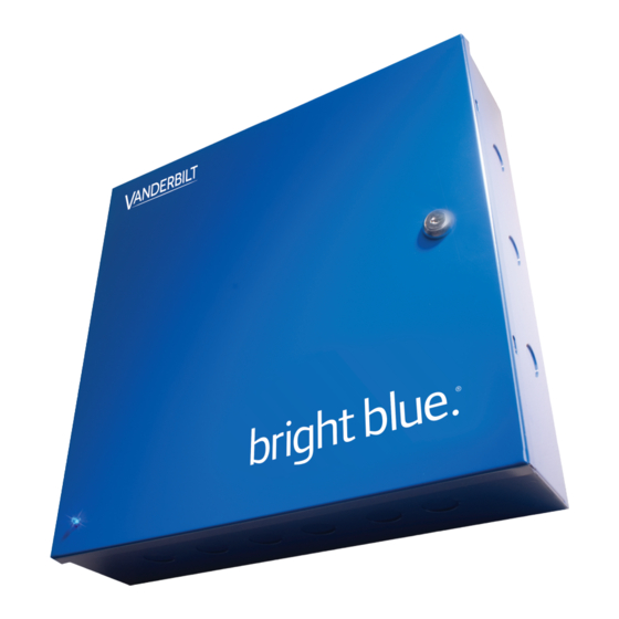
- Page 1 VANDERBILT INDUSTRIES bright blue Manual ®...
- Page 2 Information contained in this manual is subject to change without notice and does not represent any commitment on the part of Vanderbilt Industries. Vanderbilt Industries assumes no responsibility or liability for any errors or inaccuracies that may appear in this documentation.
-
Page 3: Table Of Contents
Contents Contents Vanderbilt Industries Copyright Notice UL Listing Summary Compatible UL evaluated equipment ......................... 12 Hardware Not UL Evaluated..........................12 Firmware Designation ............................13 UL Evaluated Firmware ............................13 The following should be incorporated into the system: ..................13 Operation Testing and Maintenance ........................14 Operation Testing ........................... - Page 4 DHCP Configuration ..........................37 bright blue Date and Time Setup ........................39 Using the bright blue software to set date and time ................39 Using the Discovery and Configuration Tool to set date and time............43 Battery Replacement ............................46 VBB-RI Overview ................................
- Page 5 Contents Pins Left at Default ..........................51 Pins Not Used ............................52 Connecting to bright blue ........................... 52 Optional - Powering VBB-RI Directly From a Power Supply ..............53 Addressing the VBB-RI ........................... 53 Connecting to Read Head ..........................54 Recommended Wire Chart: VBB-RI to Reader Head ................
- Page 6 Contents SBB-RI Pin Layout ............................. 66 SBB-RI Pin Functions ..........................67 Connecting to bright blue ........................... 68 Optional - Powering SBB-RI Directly From a Power Supply ..............69 Addressing the SBB-RI ........................... 69 Connecting to Read Head ..........................70 Recommended Wire Chart: SBB-RI to Reader Head ................70 P3 - SBB-RI pin connections ........................
- Page 7 Reboot and Reset to Default IP Address ....................107 Power Down and Reset to Default IP Address ..................107 Connecting to bright blue ..........................108 Connecting to Read Head ..........................109 Recommended Wire Chart: VBB-NRI G2 to Reader Head ..............109 7 &...
- Page 8 J3 – On Board Tamper Connection ...................... 116 J4 – RS485 Communication Line Terminator ..................116 D1 (A) / D2 (B) – Status LEDs ......................117 Connecting to bright blue ..........................117 Optional - Powering VRI-1 Directly From a Power Supply ..............118 Addressing ............................119 Connecting to Read Head ..........................
- Page 9 Contents Connecting to bright blue ..........................127 Optional - Powering Directly From a Power Supply ................128 Addressing ............................129 Connecting to Read Head ..........................130 Recommended Wire Chart: VRI-1S3 to Reader Head ................. 130 TB4 – Reader Head Connections ......................130 XCEED ID XF 1050 Proximity Reader ....................
- Page 10 Panel Interface Module (PIM400-485-VBB) ..................150 AD-400 Series Wireless Locks ......................151 WRI400 ..............................153 Wiring Instructions ............................154 Wiring between bright blue and PIM400 ....................154 PIM400 Configuration ............................155 Log In to SUS ............................155 Pair to PDA ............................155 Set PIM400 Address ..........................
- Page 11 Schlage Wireless Modules ..........................207 WA Series Locks (WA) ......................... 207 Wireless Reader Interface (WRI – Indoor or Outdoor) ................209 Wiring instructions ............................210 Wiring between bright blue and PIM Module ..................211 Wireless reader modules configuration ....................212...
- Page 12 VEVMS-VBB Video Server Integration Overview ................................220 Cameras ............................... 221 Configuration ..............................222 Viewing bright blue Transaction Alarms ......................228 Searching for bright blue Transaction Alarms ....................231 Troubleshooting Overview ................................234 Device Communication ............................ 234 Device Addressing Issues ........................234 Wiring Problems ............................
-
Page 13: Ul Listing Summary
12 bright blue Installation Manual UL Listing Summary Compatible UL evaluated equipment Vanderbilt Equipment ▪ Vanderbilt AP02 (pending) ▪ VBB-RI ▪ VBB-NRI ▪ VBB-NRI G2 ▪ SBB-RI (Legacy) XCEED-ID Equipment ▪ XF1050 Supported Proximity Cards ▪ Standard 26-bit Wiegand Format ▪... -
Page 14: Firmware Designation
UL has evaluated firmware v6.31 in the VBB-NRI G2 The following should be incorporated into the system: The UL 294 requires the bright blue controller enclosure and the VBB-RI enclosure to have a tamper ▪ switch that will generate an alarm whenever the enclosure is opened. Connect the tamper switch flying leads to a UL Listed burglar alarm system or UL Listed local siren/annunciator. -
Page 15: Operation Testing And Maintenance
Operation Testing and Maintenance Operation Testing Once bright blue and system components are installed, log into the system and set up a cardholder with a credential and access. Present that credential at read head to test. A green LED indicates system is working. -
Page 16: Declaration Of Conformity
Certify that the equipment described below conforms with the essential requirements of the following European Directive: Electromagnetic Compatibility (EMC) 2004/108/EC Conforming Apparatus VBB Vanderbilt bright blue Reader Controller VBB-NRI Vanderbilt bright blue Network Reader Interface VBB-RI Vanderbilt bright blue Reader Interface Serial Numbers Serial Number Starting with BB100,000 Harmonized Standards... -
Page 17: Preface
16 bright blue Installation Manual Preface This manual describes the installation and wiring procedures for the bright blue controller and peripheral devices. Who should use this book This installation manual provides guidelines for installing and configuring the bright blue controller and the hardware that interfaces with it. -
Page 18: Symbols And Conventions
Disclaimer: Disclaimers provide information that should be considered by the technician. U.S./International Technical Support If any problems are encountered while installing or operating bright blue, please contact our technical support team for assistance. U.S. Vanderbilt Technical Support: Phone: 855-316-3900 International Vanderbilt Technical Support: Phone: 973-316-3900 Vanderbilt Technical Support: E-mail: techsupport@vanderbiltindustries.com... -
Page 19: Before Installation
18 bright blue Installation Manual Before Installation This section provides information on what should be considered before installing the bright blue hardware. Requirements ▪ Check to see that all the equipment necessary for the installation is on hand. Make sure all the necessary tools to properly install the equipment, i.e. -
Page 20: Environmental Consideration
Before Installation Environmental Consideration bright blue (VBB), the VBB-NRI and the VBB-RI must be installed indoors within the protected premises in ▪ a clean and a dust free environment. ▪ Ambient temperature: 32F to 120F (0 C to 49C) ▪... -
Page 21: Web Browser Requirements
Web Browser Requirements Internet Explorer 11 bright blue has been tested on IE 11 running on the Windows 10 operating system. Any machine with the recommended amount of memory for Windows 10 will meet the memory requirements for Internet Explorer 11. -
Page 22: Device Power Requirements
Example 2: bright blue One power supply is going to be used to power 7 Schlage VIP locks, 2 VBB-RIs and VIP locks require 600mA @ 12 VDC, VBB-RIs require 300mA, bright blue requires 250mA ▪ ▪ 600mA x 7 = 4200mA (for the VIPs) ▪... -
Page 23: Bright Blue
Vanderbilt bright blue Embedded Controller Overview The bright blue system is based on the Vanderbilt AP02 controller and is equipped with 10 / 100 Base-T Ethernet connection with two RS-485 serial ports and two onboard reader interfaces capable of Wiegand or Magstripe input. -
Page 24: Highlights
The bright blue controller is designed to provide power from a power supply to a number of different devices. The power supply(s) must be large enough to power the bright blue controller and all attached devices. Make sure that the total power requirements for all devices does not exceed the output of the power supply(s) in use (see specific device chapters for power requirements). -
Page 25: Power Method 1 - Single Power Supply
24 bright blue Installation Manual Power method 1 - Single Power Supply Utilize a single UL Listed Power Limited power supply: Connect power cables from the power supply to Main Power In VBB in order to power bright blue ▪ ▪... -
Page 26: Enclosure Installation
Enclosure Installation bright blue - An enclosure with a hinged door and a lock is included with each bright blue system. Enclosure The flying leads of the tamper switch should be attached to a UL Listed burglar alarm system or Listed local siren/annunciator. -
Page 27: Bright Blue Pin Layout
26 bright blue Installation Manual bright blue Pin Layout bright blue Pin Functions Power input for bright blue. 12VDC or 24VDC. MAIN POWER IN VBB: ▪ Pin 1 is (+) ▪ Pin 2 is (-) POWER IN DEVICES 1 - 8: Power input for Channel 1, Devices 1-1 -- 1-8. - Page 28 Chapter 1 bright blue ▪ Pin 2 is (-) POWER IN DEVICES 9 - 16: Power input for Channel 1, Devices 1-9 -- 1-16. 12VDC or 24VDC. ▪ Pin 1 is (+) ▪ Pin 2 is (-) POWER IN DEVICES 1 - 8: Power input for Channel 2, Devices 2-1 -- 2-8.
- Page 29 Pin 4 is (-) Warning : The polarity of Device 1-1 to 2-16 connections has been reversed from the Rev B controller. If changing from the bright blue Rev B controller to newer bright blue controllers , the positive and negative wires need to be reversed for all devices.
-
Page 30: Functions On Ap02 Controller
Chapter 1 bright blue Functions On AP02 Controller microSD card slot. USB Ports (reserved for future use). 15 RS485 Termination (default = Off) 16 RS485 Termination (default = Off) 18 PASS 12V = Reader Power Select 12 V Available to Reader Ports (min 20 V in) Input Power "Passed Through"... -
Page 31: Bright Blue Led Indicators
IP Configuration The IP address of bright blue has to be configured so that it can communicate with a web browser. Configuration should occur after the controller is fully installed. There are two methods to configure the IP address: Static IP and DHCP which are detailed below. - Page 32 Chapter 1 bright blue Control Panel Click on . The Control Panel window will open. Network Connections Click on . The Network Connections window will open. VBBIM09/33/20 v5.0.3...
- Page 33 Click the button. The Internet Protocol (TCP/IP) Properties window will open. Make a note of the existing settings. These will need to be restored at the end of the bright blue configuration process to return the PC to its usual settings.
- Page 34 Open a web browser. Go to http://192.168.168.250 If dip switch 1 of S1 on the bright blue controller is in the "ON" position then this window will open: Continue to this website (not This message is not an error and should be bypassed. Click on recommended) The bright blue home page will open.
- Page 35 34 bright blue Installation Manual Log in. Enter User ID. Default User ID is usr. Enter Password. The default password is "password". button. The bright blue main window will open. Log In Click on the...
- Page 36 Chapter 1 bright blue Utilities Click on the button on the left side of the screen. The System Utilities window will open. VBBIM09/33/20 v5.0.3...
- Page 37 Save Changes 10 Click on the button. The Utilities - Network Settings pop-up window will open. button. The connection to bright blue will be lost as the network settings are Continue 11 Click on the updated.
-
Page 38: Dhcp Configuration
14 Restore the network settings on the PC (follow step 2 above to access the network settings of the PC). 15 Open a web browser. 16 Enter http:// followed by the new IP address into the browser. The bright blue home page will open and bright blue's IP address is successfully configured. - Page 39 38 bright blue Installation Manual Run the Discovery and Configuration tool. button to search for bright blue controllers. Click on the Edit the default values. Select which controller to configure. Device Configuration Click on the button. The Device Configuration window will open.
-
Page 40: Bright Blue Date And Time Setup
Date and Time Setup The date and time for bright blue has to be set up for the system to work properly. The date and time can be entered in two ways: 1) Through the bright blue software. 2) Using the Discovery and Configuration Tool as described below. - Page 41 Configuration chapter for details. If dip switch 1 of S1 on the bright blue controller is in the "ON" position then this window will open: Continue to this website (not This message is not an error and should be bypassed. Click on recommended) The bright blue home page will open.
- Page 42 Chapter 1 bright blue button. The bright blue main window will open. Log In Click on the VBBIM09/33/20 v5.0.3...
- Page 43 42 bright blue Installation Manual Utilities Click on the button on the left of the main screen. The System Utilities window will open. Set system date, time and time zone Click on the button. The Utilities - System Date, Time, and Time...
-
Page 44: Using The Discovery And Configuration Tool To Set Date And Time
Click on the button. The system time, date, and time zone will be updated. Using the Discovery and Configuration Tool to set date and time Connect the PC running the Discovery and Configuration tool to the bright blue controller. VBBIM09/33/20 v5.0.3... - Page 45 Network Connection - Using a regular network cable, the controller can be connected to a hub or switch that is on the same network as the PC. Run the Discovery and Configuration tool. button to search for bright blue controllers. Click on the...
- Page 46 Chapter 1 bright blue Select the bright blue controller and click on the Device Configuration button. The Device Configuration window will open. Click on the Clock tab. Click on the Set the Clock To button. Click on the Synchronize clock to this computer check box to select it.
-
Page 47: Battery Replacement
Close the Discovery and Configuration Tool. Battery Replacement The bright blue controller uses a UL Listed CR2032 or equivalent 3V Lithium Coin Cell battery. The battery should be replaced every year by a trained technician. Battery can be replaced without powering down controller. -
Page 48: Vbb-Ri
Reader Interface Overview The VBB-RI is a Reader Interface between bright blue and card readers. The VBB-RI offers a cost-effective, modular approach to access control system design. Reader Interfaces can connect to a variety of different read head technologies supported by bright blue. These include both Magnetic Stripe (not evaluated by UL) and Proximity readers. -
Page 49: Highlights
▪ standby power. Features ▪ Supports one read-head credential Connects directly to the communication channels on the bright blue controller via RS-485 protocol ▪ ▪ Includes Two 2 amp, form C, single pole/double throw, mechanically latching relay ▪ Connection for one multi-color LED for access granted or access denied indication ▪... -
Page 50: Vbb-Ri Enclosure
Chapter 2 VBB-RI VBB-RI Enclosure VBB-RI Enclosure - An enclosure with a hinged door is included for each VBB-RI. The flying leads of the tamper switch should be attached to a UL Listed burglar alarm system or Listed local siren/annunicator. Features ▪... -
Page 51: Environmental Conditions
50 bright blue Installation Manual Environmental conditions ▪ Ambient Temperature: 0º to 49º C or 32º to 120º F ▪ The room must be dust free and clean. ▪ It is optimal to mount the enclosure on fire rated plywood which is affixed to a cinder block wall or a wall covering i.e. -
Page 52: Vbb-Ri Pin Functions
Chapter 2 VBB-RI VBB-RI Pin Functions P4 - Power source and communication wiring. Used to connect bright blue to the VBB-RI. ▪ Pin 1 is Ground (GND) ▪ Pin 2 is Data B (TXB) ▪ Pin 3 is Data A (RXA) ▪... -
Page 53: Pins Not Used
Device connectors (Device 1-1 through 2-16) on the bright blue controller can be used to communicate with P4 on a VBB-RI. The below example is using Device 1-1 on the bright blue controller and P4 on the VBB-RI. -
Page 54: Optional - Powering Vbb-Ri Directly From A Power Supply
W10 on the VBB-RI consists of four jumpers that can be combined to set the address for the device. It is recommended that the set address correspond to the slot on the bright blue controller it is connected to. For example, if the VBB-RI is connected to the bright blue controller at Device 1-15 (Channel 1, Address 15) then the jumpers on the VBB-RI should equal 15. -
Page 55: Connecting To Read Head
54 bright blue Installation Manual VBB-RI Address Chart VBB-RI Address Jumper Locations VBB-RI Address Jumper Locations 1 2 4 8 1 2 4 2 4 8 1 4 8 1 2 8 None Connecting to Read Head The VBB-RI reader interface can communicate to many different read heads. Provided here are the pin outs for the most commonly used read-heads. -
Page 56: P3 - Vbb-Ri Pin Connections
Chapter 2 VBB-RI P3 - VBB-RI Pin Connections XCEED ID XF 1050 Proximity Reader Proximity Read Head Pin Connections VBB-RI Proximity Reader PIN 1 (CLK) DATA 0 (GREEN) Pin 2 (DAT) DATA 1 (WHITE) Pin 3 (GND) GROUND (BLACK) Pin 4 (PWR) POWER (RED) Pin 5 (GRN) LED (ORANGE) -
Page 57: Magnetic Stripe Reader
56 bright blue Installation Manual Magnetic Stripe Reader Magnetic Stripe Read Head Pin Connections VBB-RI Magnetic Stripe Reader PIN 1 (CLK) DATA 0 (WHITE) Pin 2 (DAT) DATA 1 (GREEN) Pin 3 (GND) GROUND (BLACK) Pin 4 (PWR) POWER (RED) -
Page 58: Vbb-Obri
Onboard Reader Interface Overview The VBB-OBRI is an onboard Reader Interface between bright blue and card readers. These 2 included Reader Interfaces can connect to a variety of different read head technologies supported by bright blue. These include both Magnetic Stripe (not evaluated by UL) and Proximity readers. -
Page 59: Highlights
Powered directly from bright blue ▪ Features ▪ Supports one read-head attached to each reader interface Mounted directly on the bright blue Vanderbilt AP02 Controller ▪ ▪ Includes Two 2 amp, form C, single pole/double throw, mechanically latching relays total ▪... -
Page 60: Pin Layout
Chapter 3 VBB-OBRI PIN Layout Onboard Reader Interface Connections: ▪ Reader 1 (OUT1, IN1, IN2) or alternately (OUT1, OUT2, IN1, IN2, IN3 IN4) ▪ Reader 2 (OUT2, IN3, IN4) or alternately not used PIN Functions 1 Power / VIN • + is Power •... - Page 61 60 bright blue Installation Manual 3 Relay 2 – Max 30 VDC @ 2 A • NC is Normally Closed • C is Common • NO is Normally Open The VBB-OBRI has four unsupervised contact points. Unsupervised door contacts have maximum wire length of 2,000 feet.
-
Page 62: Reader And I/O Assignment
No jumper will provide 0 VDC Warning: Serious damage may occur to the read-head if this jumper is set incorrectly. Please check the read head voltage requirements. 24 bright blue Network Connection Reader and I/O Assignment The VBB-OBRI Supports 2 Door Configurations: •... -
Page 63: Connecting To Bright Blue
Addressing The VBB-OBRI readers are addressed using the bright blue software. Please refer to the bright blue User Manual under Door Setup. Connecting to Read Heads The VBB-OBRI reader interface can communicate to many different read heads. Provided here are the pin outs for the most commonly used read-heads. -
Page 64: Proximity Reader
Chapter 3 VBB-OBRI Proximity Reader Proximity Read Head Pin Connections VSRC-A Proximity Reader 9 PIN A (CLK) DATA 0 (GREEN) DATA 1 (WHITE) 9 PIN B (DAT) GROUND (BLACK) 9 PIN - (GND) POWER (RED) 9 PIN + (GND) LED (ORANGE) 10 PIN 1 (LED) NOT USED 10 PIN 2 (NA) -
Page 65: Sbb-Ri (Legacy)
Reader Interface (SBB-RI Legacy) Overview The Legacy SBB-RI is a Reader Interface between bright blue and card readers. The SBB-RI offers a cost- effective, modular approach to access control system design. Reader Interfaces can connect to a variety of different read head technologies supported by bright blue. -
Page 66: Highlights
▪ standby power. Standard Features ▪ Supports one read-head credential Connects directly to the communication channels on the bright blue controller via RS-485 protocol ▪ ▪ Includes Two 2 amp, form C, single pole/double throw, mechanically latching relay ▪ Connection for one multi-color LED for access granted or access denied indication ▪... -
Page 67: Environmental Conditions
66 bright blue Installation Manual Environmental conditions ▪ Ambient Temperature: 0º to 49º C or 32º to 120º F ▪ The room must be dust free and clean. ▪ It is optimal to mount the enclosure on fire rated plywood which is affixed to a cinder block wall or a wall covering i.e. -
Page 68: Sbb-Ri Pin Functions
Chapter 4 SBB-RI (Legacy) SBB-RI Pin Functions P4 - Power source and communication wiring. Used to connect bright blue to the SBB-RI. ▪ Pin 4 is Ground ▪ Pin 3 is Data B ▪ Pin 2 is Data A ▪... -
Page 69: Connecting To Bright Blue
Device connectors (Device 1-1 through 2-16) on the bright blue controller can be used to communicate with P4 on a SBB-RI. The below example is using Device 1-1 on the bright blue controller and P4 on the SBB-RI. -
Page 70: Optional - Powering Sbb-Ri Directly From A Power Supply
W2 on the SBB-RI consists of four jumpers that can be combined to set the address for the device. It is recommended that the set address correspond to the slot on the bright blue controller it is connected to. For example, if the SBB-RI is connected to the bright blue controller at Device 1-15 (Channel 1, Address 15) then the jumpers on the SBB-RI should equal 15. -
Page 71: Connecting To Read Head
70 bright blue Installation Manual SBB-RI Address Chart SBB-RI Address Jumper Locations SBB-RI Address Jumper Locations 1 2 4 8 1 2 4 2 4 8 1 4 8 1 2 8 None Connecting to Read Head The SBB-RI reader interface can communicate to many different read heads. Provided here are the pin outs for the most commonly used read-heads. -
Page 72: P3 - Sbb-Ri Pin Connections
Chapter 4 SBB-RI (Legacy) P3 - SBB-RI pin connections XCEED ID XF 1050 Proximity Reader Proximity Read Head Pin Connections SBB-RI Proximity Reader PIN 1 (CLK) DATA 0 (GREEN) Pin 2 (DAT) DATA 1 (WHITE) Pin 3 (GND) GROUND (BLACK) Pin 4 (PWR) POWER (RED) Pin 5 (GRN) -
Page 73: Magnetic Stripe Reader
72 bright blue Installation Manual SBB-RI Proximity Reader Pin 7 (BUZ) NOT USED Magnetic Stripe Reader Magnetic Stripe Read Head Pin Connections SBB-RI Magnetic Stripe Reader PIN 1 (CLK) DATA 0 (WHITE) Pin 2 (DAT) DATA 1 (GREEN) Pin 3 (GND) -
Page 74: Vbb-Nri
The VBB-NRI is a Networked Reader Interface that communicates with bright blue via a network connection. The VBB-NRI offers a cost-effective, modular approach to access control system design. Networked Reader Interfaces can connect to a variety of different read head technologies supported by bright blue. These include both Magnetic Stripe and Proximity readers. -
Page 75: Highlights
Communicates via network protocol at 10Base-T ▪ Powered locally by a UL294 Listed Power-Limited, Power Supply capable of 4 hours standby power. OPTIONAL - can be powered directly from bright blue. (See Cable Requirement Chart for details) ▪ Standard Features ▪... -
Page 76: Environmental Conditions
VBB-NRI IP Configuration The IP address of the VBB-NRI has to be configured so that it can communicate with bright blue. Configuration should occur after the reader interface is fully installed. There are two methods to configure the IP address: Static IP and DHCP which are detailed below. - Page 77 76 bright blue Installation Manual Configure the PC's network settings to communicate with the VBB-NRI Start Click on the button. Control Panel Click on . The Control Panel window will open. Network Connections Click on . The Network Connections window will open.
- Page 78 Chapter 5 VBB-NRI Local Area Connection Click on . The Local Area Connection Properties window will open. Internet Protocol (TCP/IP) Scroll down and select Properties Click the button. The Internet Protocol (TCP/IP) Properties window will open. Make a note of the existing settings. These will need to be restored at the end of the VBB-NRI configuration process to return the PC to its usual settings.
- Page 79 78 bright blue Installation Manual Use the following IP address Click on the button. IP address Enter 192.168.168.200 into the field. Subnet mask Enter 255.255.255.0 into the field. Click on the button. The PC's network settings are now compatible with the default VBB-NRI.
- Page 80 Enter a Secondary DNS server into the Secondary DNS server field. Consult with network technicians to get an address that is compatible with the existing network. Click on the Update button. Make a note of the IP address as it will be used in the bright blue Door Setup section.
-
Page 81: Dhcp Configuration
80 bright blue Installation Manual The Static IP address of the VBB-NRI has been set. Note: The Static IP address can also be set using the Discovery and Configuration Tool. Follow the directions below for DHCP but select the Static IP configuration option and manually enter the IP address and Subnet mask. - Page 82 Chapter 5 VBB-NRI Click on the button to search for VBB-NRI. Edit the default values. Select which VBB-NRI to configure. If multiple VBB-NRIs are discovered, use the Serial Number to determine which to configure. Device Configuration Click on the button to open the Device Configuration window. Network Click on the tab.
-
Page 83: Configuration Gui (Graphic User Interface)
82 bright blue Installation Manual Make a note of the IP Address, it will be used by the bright blue interface to configure the VBB-NRI. Exit the Discovery and Configuration program. The DHCP address of the VBB-NRI has been set. - Page 84 Chapter 5 VBB-NRI The Host Name is used to access and setup the VBB-NRI using Dynamic DNS in conjunction with DHCP. Consult with network technicians for details on setting up your network in this manner. DHCP - This setting sets up the VBB-NRI to use a DHCP server on your network (use only if you have a DHCP server on the network).
-
Page 85: Vbb-Nri Pin Layout
84 bright blue Installation Manual ▪ Locked - The relay will be deactivated when communication is lost. In most installations this will mean that the door will become secured. ▪ Power On bright blue - This section is used to define the behaviour of Relay 1 while is reloading the VBB-NRI after a power loss. -
Page 86: Vbb-Nri Pin Functions
P1 - Power source wiring. Used to supply power to the VBB-NRI. ▪ Pin 1 is Ground Pin 2 is RXA and is not used with bright blue ▪ Pin 3 is TXB and is not used with bright blue ▪... -
Page 87: Pins Left At Default
86 bright blue Installation Manual ▪ Pins 3&4 - Enable/Disable Telnet. Enabled by default. If jumpered together, Telnet is disabled ▪ Pins 5&6 - Enable/Disable Discovery protocol. Enabled by default. If jumpered together, the Discovery protocol is disabled, meaning that the Discovery tool will NOT find the unit. -
Page 88: Connecting To Bright Blue
Connecting to bright blue There is no direct connection between the VBB-NRI and bright blue. They need to be on the same network and the proper IP address of the VBB-NRI needs to be entered when setting up the door (see the VBB-NRI IP Configuration section for details) for them to communicate. -
Page 89: Connecting To Read Head
88 bright blue Installation Manual Connecting to Read Head The VBB-NRI reader interface can communicate to many different read heads. Provided here are the pin outs for the most commonly used read-heads. The connection is different for each reader type. See the Recommended Wire Chart below for the proper wire type and lengths. -
Page 90: Proximity Reader
Chapter 5 VBB-NRI Proximity Reader Proximity Read Head Pin Connections VBB-NRI Proximity Reader PIN 1 (CLK) DATA 0 (GREEN) Pin 2 (DAT) DATA 1 (WHITE) Pin 3 (GND) GROUND (BLACK) Pin 4 (PWR) POWER (RED) Pin 5 (GRN) LED (ORANGE) Pin 6 (RED) NOT USED Pin 7 (IBT) -
Page 91: Installing Diode For Lock Wiring - Relay
90 bright blue Installation Manual Installing Diode for Lock Wiring - Relay A diode is supplied with the VBB-NRI which should be fitted across 12V and COM to protect the relay contacts. The lock is wired across 12V and COM. A 0V link to COM is then required to complete the circuit. This will be wired to NO or NC depending on lock type: Fail Open / Fail Closed (diagram above shows Fail Open). -
Page 92: Verifying Upgrade/Checking Version Number
Chapter 5 VBB-NRI Example: tftp -I 10.45.49.78 put image_r129_k1226.SriUpd (the name of the image will vary depending on the release of the firmware). You will receive the following message when the file is sent to the VBB-NRI. It may take a few minutes for the board to update to the latest firmware after the message is received. - Page 93 92 bright blue Installation Manual Example: http://10.45.49.65/index_ver.html Version Display Click on the button. The full SRI Application Version Display window will open. Check the Geomain_ nri field which displays what revision of firmware was loaded to the VBB-NRI during the upgrade. If the data in this field corresponds to the version upgrade, your upgrade is successful.
-
Page 94: Vbb-Nri G2
Vanderbilt bright blue Network Reader Interface (VBB-NRI Generation 2) Overview The VBB-NRI G2 is a Networked Reader Interface that communicates with bright blue via a network connection exactly like the previous generation VBB-NRI. The VBB-NRI G2 offers a cost-effective, modular approach to access control system design. -
Page 95: Highlights
Communicates via network protocol at 10Base-T ▪ Powered locally by a UL294 Listed Power-Limited, Power Supply capable of 4 hours’ standby power. OPTIONAL - can be powered directly from bright blue (see Cable Requirement Chart for details). ▪ Standard Features ▪... -
Page 96: Environmental Conditions
VBB-NRI G2 IP Configuration The IP address of the VBB-NRI G2 has to be configured so that it can communicate with bright blue. Configuration should occur after the reader interface is fully installed. There are two methods to configure the IP address: Static IP and DHCP which are detailed below. - Page 97 96 bright blue Installation Manual Configure the PC's network settings to communicate with the VBB-NRI G2 Start Click on the button. Control Panel Click on . The Control Panel window will open. Network Connections Click on . The Network Connections window will open.
- Page 98 Chapter 6 VBB-NRI G2 Local Area Connection Click on . The Local Area Connection Properties window will open. Internet Protocol (TCP/IP) Scroll down and select Properties Click the button. The Internet Protocol (TCP/IP) Properties window will open. m) Make a note of the existing settings. These will need to be restored at the end of the VBB-NRI G2 configuration process to return the PC to its usual settings.
- Page 99 98 bright blue Installation Manual Use the following IP address Click on the button. IP address Enter 192.168.168.200 into the field. Subnet mask Enter 255.255.255.0 into the field. Click on the button. The PC's network settings are now compatible with the default VBB-NRI G2.
-
Page 100: Dhcp Configuration
Enter a Secondary DNS server into the Secondary DNS server field. Consult with network technicians to get an address that is compatible with the existing network. Click on the Update button. Make a note of the IP address as it will be used in the bright blue Door Setup section. - Page 101 100 bright blue Installation Manual Click on the button to search for VBB-NRI G2. Edit the default values. Select which VBB-NRI G2 to configure. If multiple VBB-NRI G2s are discovered, use the Serial Number to determine which to configure. Device Configuration Click on the button to open the Device Configuration window.
- Page 102 Click on the button to apply the change. Make a note of the IP Address, it will be used in bright blue to configure the VBB-NRI G2. Exit the Discovery and Configuration program. The DHCP address of the VBB-NRI G2 has been set.
-
Page 103: Configuration Gui (Graphic User Interface)
102 bright blue Installation Manual Configuration GUI (Graphic User Interface) Go to https://VBB-NRI_G2_IP_Address to access the Configuration Application (PW = “SECAdmin1”). Main Settings Hostname - This displays the name of the specific VBB-NRI G2 board. The default name should not be changed. - Page 104 ▪ Power On bright blue - This section is used to define the behavior of Relay 1 while is reloading the VBB-NRI G2 after a power loss. In the case of a power failure Relay 1 will become deactivated. When...
- Page 105 The Session Length drop down can be used to adjust the Configuration Application session inactivity timer. Vanderbilt ships VBB-NRI G2 with Dipswitch 1 = ON which allows access to the Configuration application. Set Dipswitch 1 = OFF to disable Configuration access. PING and Auto-discovery will also be disabled (i.e. the Discovery and Configuration Tool will not be able to locate the VBB-NRI G2).
-
Page 106: Vbb-Nri G2 Pin Layout
Chapter 6 VBB-NRI G2 Press and Hold the Tamper Switch 17 AND Press and Release the Reset Button 24 three (3) times in succession. Release the Tamper Switch 17 . A one (1) second beep will be heard on the 2 and 3 Reset Button activations. - Page 107 106 bright blue Installation Manual • NC is Normally Closed • C is Common • NO is Normally Open The VBB-NRI G2 has four unsupervised contact points. Unsupervised door contacts have maximum wire length of 2,000 feet. 5 Contact Inputs 1 & 2 •...
-
Page 108: Factory Reset And Power Down
(4) seconds. The buzzer will begin to beep rapidly after five (5) seconds – release the Reset Button and the board will reboot. The Network Settings will reset to the Vanderbilt Defaults on reboot. -
Page 109: Connecting To Bright Blue
Connecting to bright blue There is no direct connection between the VBB-NRI G2 and bright blue. They need to be on the same network and the proper IP address of the VBB-NRI G2 needs to be entered when setting up the door (see the VBB-NRI G2 IP Configuration section for details) for them to communicate. -
Page 110: Connecting To Read Head
Chapter 6 VBB-NRI G2 Connecting to Read Head The VBB-NRI G2 reader interface can communicate to many different read heads. Provided here are the pin outs for the most commonly used read-heads. The connection is different for each reader type. See the Recommended Wire Chart below for the proper wire type and lengths. -
Page 111: Proximity Reader
110 bright blue Installation Manual Proximity Reader Proximity Read Head Pin Connections VBB-NRI G2 Proximity Reader 9 PIN A (CLK) DATA 0 (GREEN) DATA 1 (WHITE) 9 PIN B (DAT) GROUND (BLACK) 9 PIN - (GND) POWER (RED) 9 PIN + (GND) -
Page 112: Installing Diode For Lock Wiring - Relay
NO or NC depending on lock type: Fail Open / Fail Closed (diagram above shows Fail Open). Upgrading Firmware The VBB-NRI G2 firmware can only be updated via SSH. Vanderbilt recommends using WinSCP. The instructions provided below assume WinSCP is used to make the SSH connection to the VBB-NRI G2. -
Page 113: Verifying Upgrade/Checking Version Number
Navigate to the location of the update file in the right pane of WinSCP. Copy the image file *.SMSUpd file provided by Vanderbilt into the tmp/tftp folder in the left pane of WinSCP. Close WinSCP and the update will be applied automatically. -
Page 114: Overview
Single Reader Interface Overview The VRI-1 is a Reader Interface between the bright blue and card readers. The VRI-1 offers a cost-effective, modular approach to access control system design. The VRI-1 works similarly to the VRINX but utilizes the SMS- M protocol. -
Page 115: Features
Features ▪ Supports one read-head credential Connects directly to the communication channels on the bright blue controller via RS-485 protocol ▪ ▪ Two form C, single pole/double throw, 30 VDC mechanically latching relays: K1 rated @ 5A; K2 rated @ 1A ▪... -
Page 116: Environmental Conditions
Configuration The VRI-1 will be connected to the bright blue via RS-485 protocol. A maximum of 16 reader interfaces can be connected to one bright blue data channel. Wire runs are limited to 4,000 feet (Data Only) from the bright blue to a VRI-1 (see Recommended Wire Chart). -
Page 117: Pin Functions
In a multiplex configuration, each VRI-1 board is connected to any one of the Device connectors (Device 1-1 through 2-16) on the bright blue controller with TB1 for RS-485 communications and TB2 for power on a VRI-1 in parallel. A maximum of 16 VRI-1 boards can be connected to each channel in this manner. -
Page 118: D1 (A) / D2 (B) - Status Leds
Communication between the bright blue controller and a VRI-1 reader interface is via RS-485 protocol. Any one of the Device connectors (Device 1-1 through 2-16) on the bright blue controller can be used to communicate with TB1 for RS-485 communications and TB2 for power on a VRI-1. The example below shows connections between Device 1-1 on the bright blue controller and TB1, TB2 on the VRI-1. -
Page 119: Optional - Powering Vri-1 Directly From A Power Supply
VRI-1 remains via RS-485 protocol. Any one of the Device connectors (Device 1-1 through 2-16) on the bright blue controller can be used to communicate with TB1 on a VRI-1. Power will be supplied independently from the power supply to TB2 on the VRI-1. -
Page 120: Addressing
J2 on the VRI-1 consists of eight sets of jumpers that can be combined to set the address for the device, RS-485 communications baud rate and enable encryption. Record the jumper configured address of the VRI-1 and which channel it is connected to on the bright blue controller. This information will be required to set up the reader in bright blue. -
Page 121: Connecting To Read Head
120 bright blue Installation Manual Connecting to Read Head The VRI-1 reader interface can communicate to many different read heads. Provided here are the PIN outs for the most commonly used read-heads. The connection is different for each reader type. See the Recommended Wire Chart below for the proper wire type and lengths. -
Page 122: Tb4 - Reader Head Connections
Chapter 7 VRI-1 TB4 – Reader Head Connections Ground (Black) Buzzer (Not Used) LED (Orange) Clock / D1 (White) Data / D0 (Green) V0 (Red) XCEED ID XF 1050 Proximity Reader Proximity Read Head Pin Connections VRI-1 Proximity Reader PIN 1 (GND) GROUND (BLACK) PIN 2 (BZR) NOT USED... -
Page 123: Installing Diode For Lock Wiring - Relay
122 bright blue Installation Manual Installing Diode for Lock Wiring - Relay A diode is supplied with the VRI-1 which should be fitted across 12V / 24V and COM to protect the relay contacts. A diode is used to eliminate the voltage spike seen across an inductive load when supply voltage is suddenly... -
Page 124: Vri-1S3
Single Reader Interface – Series 3 Overview The new VRI-1S3 is a Reader Interface between the bright blue and card readers. The VRI-1S3 works identically to the VRI-1, utilizing the SMS-M protocol. Reader Interfaces can connect to a variety of different read head technologies supported by bright blue. -
Page 125: Features
Features ▪ Supports one read-head credential Connects directly to the communication channels on the bright blue controller via RS-485 protocol ▪ ▪ Two form C, single pole/double throw, 30 VDC mechanically latching relays: K1 rated @ 5A; K2 rated @ 1A ▪... -
Page 126: Environmental Conditions
The VRI-1S3 will be connected to the bright blue via RS-485 protocol. A maximum of 16 reader interfaces can be connected to one bright blue data channel. Wire runs are limited to 4,000 feet (Data Only) from the bright blue to a VRI-1S3 (see Recommended Wire Chart). Data communication between bright blue and the reader interfaces can be a multiplex or a daisy chain configuration. -
Page 127: Pin Functions
In a multiplex configuration, each VRI-1S3 board is connected to any one of the Device connectors (Device 1-1 through 2-16) on the bright blue controller with TB1 for RS-485 communications and TB2 for power on a VRI- 1S3 in parallel. A maximum of 16 VRI-1S3 boards can be connected to each channel in this manner. -
Page 128: D1 (A) / D2 (B) - Status Leds
Communication between the bright blue controller and a VRI-1S3 reader interface is via RS-485 protocol. Any one of the Device connectors (Device 1-1 through 2-16) on the bright blue controller can be used to communicate with TB1 for RS-485 communications and TB2 for power on a VRI-1S3. The example below shows connections between Device 1-1 on the bright blue controller and TB1, TB2 on the VRI-1S3. -
Page 129: Optional - Powering Directly From A Power Supply
Communication between the bright blue controller and the VRI-1S3 remains via RS-485 protocol. Any one of the Device connectors (Device 1-1 through 2-16) on the bright blue controller can be used to communicate with TB1 on a VRI-1S3. Power will be supplied independently from the power supply to TB2 on the VRI-1S3. -
Page 130: Addressing
S1 on the VRI-1S3 consists of eight slide switches that can be combined to set the address for the device, RS-485 communications baud rate and enable encryption. Record the switch configured address of the VRI-1S3 and which channel it is connected to on the bright blue controller. This information will be required to set up the reader in bright blue. -
Page 131: Connecting To Read Head
130 bright blue Installation Manual Connecting to Read Head The VRI-1S3 reader interface can communicate to many different read heads. Provided here are the PIN outs for the most commonly used read-heads. The connection is different for each reader type. See the Recommended Wire Chart below for the proper wire type and lengths. -
Page 132: Xceed Id Xf 1050 Proximity Reader
Chapter 8 VRI-1S3 XCEED ID XF 1050 Proximity Reader Proximity Read Head Pin Connections VRI-1 Proximity Reader PIN 1 (GND) GROUND (BLACK) PIN 2 (BZR) NOT USED PIN 3 (LED) LED (ORANGE) PIN 4 (CLK D1) DATA 1 (WHITE) PIN 5 (DAT D0) DATA 0 (GREEN) PIN 6 (V0) POWER (RED) -
Page 133: Installing Diode For Lock Wiring - Relay
132 bright blue Installation Manual Installing Diode for Lock Wiring - Relay A diode is supplied with the VRI-1S3 which should be fitted across 12V / 24V and COM to protect the relay contacts. A diode is used to eliminate the voltage spike seen across an inductive load when supply voltage is suddenly... -
Page 134: Vri-2 / Vri-2S3
Dual Reader Interface Overview The VRI-2 (green) and VRI-2S3 (red – series 3) are Reader Interfaces between the bright blue and card readers. The VRI-2 and VRI-2S3 function identically and will be referred to as VRI-2. The VRI-2 works similarly to the VRINX but utilizes the SMS-M protocol and supports 2 card reader connections. -
Page 135: Features
Board Dimensions: ▪ 10” H x 12” W x 3-1/2” D Enclosure Dimensions: 12 – 24 VDC (supplied from the bright blue or external power supply) ▪ Power requirements: ▪ 270 – 450mA (depending on input voltage plus nominal reader current to 550 mA) Power consumption: ▪... -
Page 136: Environmental Conditions
Chapter 9 VRI-2 / VRI-2S3 Environmental conditions ▪ Ambient Temperature: 0º to 70º C or 32º to 158º F ▪ The room must be dust free and clean. ▪ It is optimal to mount the enclosure on fire rated plywood which is affixed to a cinder block wall or a wall covering i.e. -
Page 137: Configuration
Configuration The VRI-2 will be connected to the bright blue via RS-485 protocol. A maximum of 16 reader interfaces can be connected to one bright blue data channel. Wire runs are limited to 4,000 feet (Data Only) from the bright blue to a VRI-2 (see Recommended Wire Chart). -
Page 138: Tb6 - Communications
Chapter 9 VRI-2 / VRI-2S3 TB6 - Communications Provides RS-485 communications between the VRI-2 and the bright blue. ▪ PIN 1 is Data A (TR+) ▪ PIN 2 is Data B (TR-) TB1 – TB5 Contact inputs The VRI-2 has eight supervised or unsupervised contact points plus cabinet Tamper and UPS Fault Monitoring contact inputs (TB5). -
Page 139: Tb10 - Tb12 Relay Outputs
138 bright blue Installation Manual TB10 – TB12 Relay Outputs The VRI-2 has six relay outputs. J15 – Read head voltage selector 12 VDC is available on Reader Ports (VIN >= 20 VDC): VIN “Passed Through” to Reader Ports: Serious damage may occur to the read-head if this jumper is set incorrectly. Please check the read-head voltage... -
Page 140: S1 -Addressing
The address of the VRI-2 is dependent on the position of the DIP switches in S1. The hardware address for each physical VRI-2 must be set to address 1 – 16 for use with bright blue. (i.e. 1A & 1B or 5A & 5B) The first reader is assigned “A”... - Page 141 140 bright blue Installation Manual ▪ LED 2: IN2 Status ▪ LED 3: IN3 Status ▪ LED 4: IN4 Status SMS VR-2 Template Applied: ▪ LED 5: IN5 Status = Request to Exit ▪ LED 6: IN6 Status = Door Status Monitor ▪...
-
Page 142: Schlage Adaptable Ad-300 Series Locks
The AD-300 Lock is an integrated, modular lock that includes all the standard peripheral devices at a secured door opening. AD-300 Locks can be integrated directly into the bright blue controller. The communication protocol is RS-485 to any of the communication channels on the bright blue controller. -
Page 143: Contacts And Pin Functions
Device connectors (Device 1-1 through 2-16) on the bright blue board can be used to communicate with J1 on an AD-300 lock. The example below shows using Device 1-1 on the bright blue board and J1 on the AD-300 lock. -
Page 144: Addressing The Ad-300 Lock
SUS Address Address Address After the AD-300 has been connected to the bright blue controller, make a note of the channel and address. This information will be required to set up the lock in the software. Schlage Utility Software User's Guide... - Page 145 144 bright blue Installation Manual Manager Log on as Select from the drop down menu. Password 123456 Enter the password into the field. Default password is Login No Device Click the button. The SUS program will open. The bottom of the screen will say Connected.
-
Page 146: Schlage Vip Locks
The Schlage VIP Lock is an integrated, modular lock that includes all the standard peripheral devices at a secured door opening. VIP Locks can be integrated directly into the bright blue controller. The communication protocol is RS-485 to any of the communication channels on the bright blue controller. -
Page 147: Contacts, Relays, And Pin Functions
- Used to set protocol type. To communicate with bright blue this must be switched to ON. ▪ OFF - VIP protocol ▪ ON - 'F' series protocol Dip Switch 7 MUST be switched to the ON position for the VIP lock to work with bright blue. Note:... -
Page 148: Connecting To Bright Blue
Communication between the bright blue controller and a VIP lock is via RS-485 protocol. Any one of the Device connectors (Device 1-1 through 2-16) on the bright blue board can be used to communicate with J3 on a VIP lock. The example below shows using Device 1-1 on the bright blue board and J3 on the VIP lock. -
Page 149: Addressing The Vip Lock
It is recommended that the set address correspond to the slot on the bright blue controller it is connected to. For example, if the VIP is connected to the bright blue controller at Device 1-2 (Channel 1, Address 2) then the switches on the VIP should equal 2. -
Page 150: Schlage Adaptable Ad-400 Series
Schlage wireless devices can be seamlessly integrated to your bright blue system. The PIM400-485-VBB communicates directly to the bright blue controller via RS-485 protocol and can support up to 16 Schlage AD-400 Series locks. Specifications and guidelines for configuring the wireless devices are in the pages that follow. -
Page 151: Schlage Ad-400 Components
The PIM400-485-VBB can be integrated with the system, it works in conjunction with the AD-400 Locks. The PIM400-485-VBB module is hard wired directly to bright blue communication channels and communicates via RS-485 protocol. The PIM400-485-VBB can support up to 16 AD-400 locks. -
Page 152: Ad-400 Series Wireless Locks
Operational environment ▪ Temperature: -35°C to +66°C ▪ Humidity: 20% RH to 95% RH (non-condensing) ▪ bright blue Operating Voltage: 12 to 24 VDC (Powered from or locally) ▪ Power consumption: 300mA max. Radio frequency (RF) - The PIM400 includes an RF Transceiver ▪... - Page 153 152 bright blue Installation Manual ▪ Card Thickness - 0.030 inches thick ▪ ANSI/ISO Standards 7810, 7811 1/51 7812, and 7813 Card Reader - Proximity Reader ▪ ANSI/BHMA A156.25 compliant ▪ Compatible with HID proximity cards ▪ Wiegand output ▪...
-
Page 154: Wri400
Chapter 12 Schlage Adaptable AD-400 Series WRI400 bright blue The WRI400 is a networked access point controller that communicates with via RF through a mating Panel Interface Module (PIM400-485-VBB). It is designed to provide wireless connectivity to electronic access control components including credential readers, door position and request to exit switches. -
Page 155: Wiring Instructions
Wiring between bright blue and PIM400 The PIM400 can receive power and data from channels 1-1 through 2-16 of bright blue as long as the channel it is connected to is receiving 12 to 24VDC. The PIM receives power at J2 and data at J5. J5 has two pins for Data A and two pins for Data B. -
Page 156: Pim400 Configuration
Chapter 12 Schlage Adaptable AD-400 Series Data Communication and Power between bright blue and PIM400 bright blue PIM400 J5 Pin 1 - A (Data A) RA- (jumper at J19) Pin 2 - B (Data B) RB+ (jumper at J20) bright blue... -
Page 157: Set Pim400 Address
156 bright blue Installation Manual Pairing Mode Put the PIM400 into (this is necessary for the PDA to be able to make changes to the PIM's settings). Link 1 (S2) On the PIM400, hold down the button. Link 2 (S3) Press the button three times while continuing to hold down the Link 1 button. - Page 158 The PIM400 will be set at address 0, with a Low value of 0 and a High Value of 7 (meaning the AD-400 locks will be addressed from 0 bright blue to 7). In the interface, the PIM400 will be addressed as 0 and the AD-400 locks will be addressed as 0 through 7.
- Page 159 158 bright blue Installation Manual Device Options Click on the button. PIM Properties Click on the option. Edit Click the tab. RS485 Define the PIM400's address by clicking on the field; this is where the PIM400's address is set. A numerical keypad will open at the bottom of the screen.
-
Page 160: Ad-400 Series Lock Configuration
Chapter 12 Schlage Adaptable AD-400 Series High Door On the option, use the up and down arrows to define the high address of the AD-400s that will communicate with this PIM400. Save 10 Click . The address of the PIM400 and the address range of the AD-400s have been set. AD-400 Series Lock Configuration Configuration of the AD-400 Series locks is accomplished by the SUS while the PDA is connected to the PIM400. -
Page 161: Diagnostics
160 bright blue Installation Manual Link Go to the tab. Select Door 10 Use the drop down menu to Set the address of the AD-400. This number will be the AD-400's address. Link 11 Click Linking Mode 12 Put the AD-400 Lock into... - Page 162 Chapter 12 Schlage Adaptable AD-400 Series Device Options Click on the button. Diagnostics Demo Mode Click on the option. The window will open. Select Door Using the drop down, select the door you wish to test. VBBIM09/33/20 v5.0.3...
-
Page 163: Wri400 Configuration
162 bright blue Installation Manual Status If the section shows , then you have successfully linked the AD-400. Now, to perform a complete operational test of the AD-400: Present your credential to the AD-400. If the door is functioning correctly the card data will appear in the Card Data field. - Page 164 Chapter 12 Schlage Adaptable AD-400 Series Manager Log on as Select from the drop down menu. Password 123456 Enter the password into the field. Default password is Login No Device Click the button. The SUS program will open. The bottom of the screen will say Connected.
-
Page 165: Additional Configuration
164 bright blue Installation Manual Link Go to the tab. Select Door 10 Use the drop down menu to Set the address of the WRI400. This number will be the WRI400's address. Link 11 Click 12 Make sure power is connected to the WRI400. - Page 166 Scroll down to the section of the Edit Tab. Change the default setting (10 Minutes) to 1 second to allow for a Door Forced or Door Held Open bright blue transaction to be read by and activate the auxiliary relay.
- Page 167 166 bright blue Installation Manual Default Configuration Active open Change the default setting of the Request to Exit option to . When done the screen should look like the following image: Correct Configuration Save Click Configure Door Position Switch Device Options...
- Page 168 Chapter 12 Schlage Adaptable AD-400 Series Default Configuration Active open Change the default setting of the Door Position Switch option to Delay Change the option to Retry Change the option to . When done the screen should look like the following image: Correct Configuration Save Click...
-
Page 169: Schlage Nde Series Wireless Locks With Engage
10 Schlage NDE or LE Series or wireless locks. Specifications and guidelines for configuring the wireless devices are in the pages that follow. For the GWE – ENGAGE Gateway to communicate with the bright blue, v4.2.0 or higher must be installed. Note: NDEB Series Wireless locks are also supported. -
Page 170: Schlage Nde Series Components
Android or iOS Smartphone with ENGAGE app for configuration The GWE – ENGAGE Gateway is hard wired to the bright blue controller communication channels via RS-485 protocol. The Gateway installation location is determined by the location of the NDE series locks (maximum distance between Gateway and NDE series locks is 100 feet) with which it will communicate wirelessly via Bluetooth. -
Page 171: Nde Series Wireless Locks
(battery pack), terminals for monitoring a clutch position switch/sensor, a card reader and a RF transceiver for communicating with a GWE – ENGAGE Gateway or smart phone (for configuration only). The GWE – ENGAGE Gateway interfaces to the bright blue reader controller via wired RS-485. Performance ▪... -
Page 172: Gwe - Engage Gateway Wiring Instructions
Power • bright blue 12 – 24 VDC • GWE – ENGAGE Gateway powered by bright blue or external 24 VDC power supply bright blue to GWE – ENGAGE Gateway • Controller to Gateway via RS-485 wiring max 4000’ Device 1 – 1 GWE –... -
Page 173: Gwe - Engage Gateway, Nde Lock And Sms Addressing
A maximum of ten (10) NDE Series wireless locks with ENGAGE can communicate with a Gateway on the same channel. The address defined in the Gateway and bright blue for the NDE locks ranges from 0 to 9. bright blue addresses will always be identical to the value displayed in the ENGAGE iOS or Android app. The ENGAGE Gateway will have the same address as the NDE lock with the lowest address. -
Page 174: Download Enage App
Open the ENGAGE app on the mobile device • Login to the unique site using the credentials provided by Vanderbilt • The initial “Manage Devices” screen will be empty until the first lock or gateway is added to the site •... - Page 175 174 bright blue Installation Manual • Click the “+” / “Add Device” in the ENAGE app to find the Gateway. • Select the Gateway. The Gateway LED will flash blue. • Click “Yes”. • Configure Device will open • Name the Gateway and click Save / Next •...
-
Page 176: Commission Nde Locks W/ Engage Technology
Do Not Modify Settings Other Than Those Specified Below During the Commissioning Process • Open the ENGAGE app on the mobile device • Login to the unique site using the credentials provided by Vanderbilt • Open the “Connect Devices” / “Site Name” screen •... -
Page 177: Configure Communications Delay And Retry Timing
• Select Save • Repeat the above process for each Schlage NDE lock to be utilized with bright blue • Logout of the ENGAGE Mobile app If the Schlage NDE lock(s) are not successfully commissioned and configured via the Android or iOS mobile... -
Page 178: Define Engage Devices In Bright Blue
Chapter 13 Schlage NDE Series Wireless Locks with ENGAGE Define ENGAGE Devices in bright blue The GWE – ENGAGE Gateway (RS-485) must be connected and defined in bright blue prior to configuring any NDE Wireless locks. • Connect to bright blue and login with USR or another administrator account... - Page 179 Define the following options: Channel Number Select the corresponding to the channel on the bright blue to which the Gateway is wired. Gateway Address Set the to match the address that is specified by the Allegion ENGAGE Mobile App.
-
Page 180: Link Nde Locks To Gwe - Engage Gateway
Link NDE Locks to GWE – ENGAGE Gateway Linking the GWE – ENGAGE Gateway and NDE Wireless Locks with ENGAGE Technology is accomplished using the Vanderbilt Discovery Tool provided with bright blue. Discovery Tool v1.4.7 or newer is required. bright blue v4.2.0 or newer is required. - Page 181 180 bright blue Installation Manual • Locate the bright blue Controller to which the GWE – ENGAGE Gateway is wired and double-click to open the Device Configuration dialog.
- Page 182 The configured Low and High NDE Lock Address will be retrieved from the Gateway and displayed The Discovery Tool will display all Addressing as required by bright blue. ENGAGE Device Addressing is 0- based while Diagnostics Addressing is 1-based. See GWE – ENGAGE Gateway, NDE Lock and bright blue Addressing above.
- Page 183 182 bright blue Installation Manual • Click “Configure” on the NDE Lock to Link • Click “Link” to initiate the linking process All dialog buttons will be disabled during the linking process for a timeout period of 15 seconds which is user configurable up to 30 seconds.
- Page 184 Chapter 13 Schlage NDE Series Wireless Locks with ENGAGE • The COMM indicator will turn green once the Lock is successfully linked to the Gateway and the Lock will exit Linking Mode (Linking indicator gray) • Click “Close” once the COMM indicator displays green Clicking the Link button on a Lock that is already Linked and communicating with an GWE –...
- Page 185 184 bright blue Installation Manual • The Lock will display communicating in the Available Locks dialog. • Repeat the above process to link additional NDE Locks to the selected Gateway • Close the dialog once all desired NDE Locks are linked to the Gateway...
- Page 186 Chapter 13 Schlage NDE Series Wireless Locks with ENGAGE • Repeat for additional GWE – ENGAGE Gateways and NDE Wireless Locks as required. • Close the Device Configuration dialog when complete • Exit the Discovery Tool Define NDE Lock Note: If using a Schlage NDE Wireless lock, a GWE - ENGAGE Gateway (RS-485) must be programmed before continuing.
- Page 187 186 bright blue Installation Manual Schlage Wireless Select from the drop-down menus at the top. Click on the radio button to the left of the type of NDE Series Wireless Lock with ENGAGE lock to be set up. Continue Installation Click on the button.
- Page 188 Chapter 13 Schlage NDE Series Wireless Locks with ENGAGE Door Setup - Edit Door Security System Click to confirm the correct lock. The window will open. Door Name Notes Complete the fields. Device Configuration Select the tab in the bottom half of the screen. Reader Type Define the following options:...
- Page 189 188 bright blue Installation Manual Access Timers 10 Now select the tab. Timers 11 Define the following options: Unlock Time Using the drop down box, define the number of seconds the door will be unlocked before the lock re-engages. Door Held Open Detect Time...
- Page 190 17 If the bright blue system has been integrated with a video server then use the Video Surveillance System Event Logging section to select which camera will be linked to this door's events. This section will be disabled if there is no connection to a video server.
- Page 191 190 bright blue Installation Manual Ensure this door is re-locked automatically at the following time/days, if Check the toggled unlocked: box to enable this feature. This will lock this door automatically at the specified time. Time: Hour Min. Use the drop down boxes to specify when the door will automatically lock.
- Page 192 Chapter 13 Schlage NDE Series Wireless Locks with ENGAGE ▪ Copy applicable settings from this door's configuration. Create a Select this along with new door record with the same security system type , to set up a new lock with the same Door Setup - settings specified for the previous lock and click .
-
Page 193: Schlage Le Series Wireless Locks
RSI protocol and can support up to 10 Schlage NDE or LE Series wireless locks. Specifications and guidelines for configuring the wireless devices are in the pages that follow. For the GWE – ENGAGE Gateway to communicate with the bright blue, v4.2.0 or higher must be installed. Note: LEB Series Wireless locks are also supported. -
Page 194: Schlage Le Series Components
Android or iOS Smartphone with ENGAGE app for configuration The GWE – ENGAGE Gateway is hard wired to the bright blue controller communication channels via RS-485 protocol. The Gateway installation location is determined by the location of the LE series locks (maximum distance between Gateway and NDE series locks is 100 feet) with which it will communicate wirelessly via Bluetooth. -
Page 195: Le Series Wireless Locks
RF transceiver for communicating with a GWE – ENGAGE Gateway or smart phone (for configuration only). The GWE – ENGAGE Gateway interfaces to the bright blue reader controller via wired RS-485. Performance ▪... - Page 196 Schlage NDE locks provide a way to lock or unlock a door and monitor access from a remote location. Schlage NDE locks are fail-safe from the protected side of the door. These locksets are controlled by the bright blue system. Door position: built-in magnetic Door Position Switch (DPS) used to report Door Open, Door Forced or Door Held events.
-
Page 197: Gwe - Engage Gateway Wiring Instructions
A maximum of ten (10) LE or NDE Series wireless locks can communicate with a Gateway on the same channel. The address defined in the Gateway and bright blue for the LE or NDE locks ranges from 0 to 9. -
Page 198: Download Enage App
See Chapter 13 – NDE Locks … the process is the same Define ENGAGE Devices in bright blue The GWE – ENGAGE Gateway (RS-485) must be connected and defined in bright blue prior to configuring any NDE Wireless locks. •... - Page 199 198 bright blue Installation Manual Schlage Wireless Select from the drop-down menus at the top. Click on the radio button to the left of the type of LE Series Wireless Lock to be set up. Continue Installation Click on the button.
- Page 200 Chapter 14 Schlage LE Series Wireless Locks Door Setup - Edit Door Security System Click to confirm the correct lock. The window will open. Door Name Notes Complete the fields. Device Configuration Select the tab in the bottom half of the screen. Reader Type Define the following options:...
- Page 201 200 bright blue Installation Manual Access Timers 10 Now select the tab. Timers 11 Define the following options: Unlock Time Using the drop down box, define the number of seconds the door will be unlocked before the lock re-engages. Door Held Open Detect Time...
- Page 202 17 If the bright blue system has been integrated with a video server then use the Video Surveillance System Event Logging section to select which camera will be linked to this door's events. This section will be disabled if there is no connection to a video server.
- Page 203 202 bright blue Installation Manual Ensure this door is re-locked automatically at the following time/days, if Check the toggled unlocked: box to enable this feature. This will lock this door automatically at the specified time. Time: Hour Min. Use the drop down boxes to specify when the door will automatically lock.
- Page 204 Chapter 14 Schlage LE Series Wireless Locks ▪ Copy applicable settings from this door's configuration. Create a Select this along with new door record with the same security system type , to set up a new lock with the same Door Setup - settings specified for the previous lock and click .
-
Page 205: Schlage Wireless Readers
H A P T E R Wireless reader Overview Schlage wireless devices can be seamlessly integrated with the bright blue system. The PIM-SBB (Legacy) communicates directly to bright blue via RS-485 protocol and can support up to 16 Schlage wireless devices. -
Page 206: Abbreviations
WAPM Wireless Reader Interface WAPM Schlage Wireless System Components There are various wireless devices that are used to integrate with bright blue. The Schlage wireless system contains two different types of modules: ▪ One wireless panel interface module (PIM) ▪... -
Page 207: Wireless Panel Interface Module - Pim-Sbb (Legacy)
Temperature: -35°C to +66°C ▪ Humidity: 20% RH to 95% RH (non-condensing) Operating Voltage: 7.5 to 14.0 VDC. Powered from any data channel on the bright blue controller that is ▪ supplying 12VDC or separately from UL listed power supply. -
Page 208: Schlage Wireless Modules
Request-to-Exit sensor/switch, an optional Request-to-Enter sensor/ switch, a power supply (battery pack), and terminals for monitoring a door position switch/sensor, a card reader, and an RF transceiver for communicating with another RF transceiver in a Panel Interface Module (PIM) which interfaces with bright blue. Performance ▪... - Page 209 - Schlage WA Series Locks provide a way to lock or unlock a door and monitor access from a remote location. They are fail-safe from the protected side of the door. These locks are controlled by bright blue. Cylindrical Type WA5200 Series ▪...
-
Page 210: Wireless Reader Interface (Wri - Indoor Or Outdoor)
Wireless Reader Interface (WRI – Indoor or Outdoor) The WRI-IN/OUT-12VDC acts as a remote card reading device that communicates via RF with bright blue through a mating Panel Interface Module (PIM). The Schlage wireless modules are powered locally with 12 VDC power supply. -
Page 211: Wiring Instructions
210 bright blue Installation Manual Power source ▪ Power Requirements - 12VDC power supply (593PI-12VDC recommended) ▪ Operating Voltage - 7.5 to 14.0 VDC Radio Frequency (RF) - The PIM includes an RF Transceiver. ▪ Spread spectrum ▪ Direct sequencing spread spectrum ▪... -
Page 212: Wiring Between Bright Blue And Pim Module
Wiring between bright blue and PIM Module The PIM can receive power and data from channels 1-1 through 2-16 of bright blue as long as the channel it is connected to is receiving 12VDC. The PIM receives power at J1 and data at J7. J7 has two pins for Data A and two pins for Data B. -
Page 213: Wireless Reader Modules Configuration
Address can be 0 through 15 (panel number 0 to 15 in the CDT). Example - if a WAPM is configured as Panel 5 (door 5) using the CDT, then its corresponding address in bright blue is five (5). -
Page 214: Installing The Cdt Software
Chapter 15 Schlage Wireless Readers Installing the CDT software CDT Requirements: ▪ Microsoft Windows XP or higher ▪ Microsoft Internet Explorer 5.0 or higher ▪ Sun Java Runtime Environment (tested with JRE version 6 update 12 or lower, automatically loaded on most computers) To install the CDT software: go to http://www.wyrelessaccess.com/... -
Page 215: Internet Options
214 bright blue Installation Manual This will check for the basic VM and install an older version onto your PC. Note: Once you have installed the older version of the Java VM, it is recommend that the file be renamed. - Page 216 (See the next step for details on address range.) Example: Channel 1 of bright blue will have two PIMs. One PIM will be interfacing with 5 WAPMs and the other will be interfacing with 6. The first PIM will have an Addr Lo of 0 and an Addr Hi of 4. The PIM Addr for this PIM will be 0.
- Page 217 If multiple PIMs are being used on the same channel it is recommended that room be left in the addressing range for later expansion. Example: Channel 1 of bright blue will have two PIMs. At time of installation one PIM will be interfacing with 5 WAPMs and the other will be interfacing with 6.
-
Page 218: Configuring The Wri
A transaction may need to be produced in order for these settings to be sent to the WRI. 10 Make a note of the address as this will be used by the bright blue user interface to configure the lock. -
Page 219: Configuring Wa Series Locks
Note: A transaction may need to be produced in order for these settings to be sent to the lock. Make a note of the address as this will be used by the bright blue user interface to configure the lock. - Page 220 Chapter 15 Schlage Wireless Readers 10 Configuration of the lock is complete. To set up another WA series lock, follow steps 1 through 9 above. Disconnecting WA Series Locks from the link mode To disconnect lock from the link mode, close the CDT application. VBBIM09/33/20 v5.0.3...
-
Page 221: Vevms-Vbb Video Server Integration
Integrating a access control panel with the will provide the ability to view and search video based on bright blue transactions. After configuring bright blue to communicate with an VEVMS Video Control MultiVideo Remote DVR/NVR, alarms can be shown in based on transactions. -
Page 222: Cameras
Chapter 16 VEVMS-VBB Video Server Integration Cameras The following cameras are compatible with the VEVMS-VBB Video Server: VBBIM09/33/20 v5.0.3... -
Page 223: Configuration
222 bright blue Installation Manual Configuration bright blue VEVMS DVR/NVR To configure to work with an , follow these steps: VEVMS DVR/NVR System Tools --> Advanced Settings VBB Service On the , go to . Click the Enable VBB Service... - Page 224 The bright blue Authentication window will open. vanderbilt Enter into the User Name field. vanderbilt Enter into the Password field. vanderbilt Enter into the Password Confirm field. Click the button. The window will close; bright blue Authentication is complete. VBBIM09/33/20 v5.0.3...
- Page 225 224 bright blue Installation Manual Video Server Settings --> Store Settings Store by Data Transaction Go to . Enable " " for any bright blue No. of Pictures cameras that will be recording based on transactions. Also configure the Before Event No.
- Page 226 This also enables the + Right Click feature in Video Control, which will display a list of the last few bright blue transactions. The Shift + Right Click number of transactions displayed using is defined in Step 2.
- Page 227 Check off " " and enter the IP Save Changes address, user name (vanderbilt) and password (vanderbilt). Click to establish a connection. If successful, the camera list will appear on the right hand side. Time Zone...
- Page 228 Chapter 16 VEVMS-VBB Video Server Integration Synchronize bright blue's date and time with the After saving the updated Time Zone, click " Video Surveillance System now. " The time will continue to be synchronized regularly between bright blue and the VEVMS DVR/NVR.
-
Page 229: Viewing Bright Blue Transaction Alarms
228 bright blue Installation Manual Viewing bright blue Transaction Alarms Pop Up Display bright blue Video Control is configured, incoming transactions from will create alarms in For details on Pop Up Display see the VEVMS Manual. View Video from the Current Alarm -... - Page 230 - Once the Alarm Silence / Acknowledge button is clicked, holding down Shift right clicking on a bright blue linked camera will display a drop down list of recent alarms. The Video Server Settings --> Store Settings Number number of alarms shown in this list is defined in in the "...
- Page 231 230 bright blue Installation Manual VVTRPlay5 VVTRPlay5 - When an alarm is selected using either of the previous two methods, the window will appear. The video associated with the transaction will play automatically. VVTRPlay5 includes standard controls to Meta Data Pause, Fast Forward, and Rewind the video transaction.
-
Page 232: Searching For Bright Blue Transaction Alarms
Chapter 16 VEVMS-VBB Video Server Integration Searching for bright blue Transaction Alarms bright blue Video can also be searched through based on transactions. This is done through the standard Find Playback utility in the application by following these steps. Select the desired Date / Time range, Facility, VEVMS DVR/NVR and Camera(s), then click the Video button. - Page 233 232 bright blue Installation Manual Event Type All Event Types Specify the or keep the default of and click OK. Playback. View the associated video in It will appear like any other video event type (VMD, Contact Input, Meta Data Event etc.), except extra fields will appear listing any...
- Page 234 Chapter 16 VEVMS-VBB Video Server Integration VBBIM09/33/20 v5.0.3...
-
Page 235: Troubleshooting
Overview This chapter details how to troubleshoot and fix various issues with bright blue. If your system is not functioning properly, check this chapter for possible fixes. If you do not find your problem here, or if the recommended fix does not solve the problem, contact technical support for assistance. -
Page 236: Upgrading Software
File Not Authorized Warning While Upgrading Check the date that bright blue is set to. This error occurs if bright blue's date is out of synch with the current date. If the date will not reset the battery needs to be changed. See the Battery Replacement section for details. -
Page 237: Date And Time
236 bright blue Installation Manual If operation is not restored contact Vanderbilt Technical Support. Date and Time Incorrect Date/Time If the system is working properly, but the date and time are not correct, then the Lithium battery on the bright blue board needs to be replaced. - Page 238 Addressing the VBB-RI • 53 Configuring WA Series Locks • 218 Addressing the VIP Lock • 148 Connecting to bright blue • 52, 62, 68, 87, 108, Allegion ENGAGE Account • 196 117, 127, 142, 147 Connecting to HHD/Coupling/Linking • 162 Battery Replacement •...
- Page 239 238 Index DHCP Configuration • 37, 80, 99 Diagnostics • 160 Installation and Configuration Steps • 24 Dimensions • 23 Installing Diode for Lock Wiring - Relay • 56, Disconnecting PIM from the link mode • 216 90, 111, 122, 132 Installing Microsoft Java Virtual Machine •...
- Page 240 Panel Interface Module (PIM400-485-VBB) • Schlage Wireless Readers • 204 Schlage Wireless System Components • 205 PIM400 Configuration • 155 Searching for bright blue Transaction Alarms • PIN Connections • 62 PIN Functions • 59, 116, 126, 136 Set PIM400 Address • 156 PIN Layout •...
- Page 241 UL Evaluated Firmware • 13 UL Listing Summary • 12 Wireless reader modules configuration • 212 Wiring between bright blue and PIM Module • Upgrading Firmware • 90, 111 Upgrading Software • 235 Wiring between bright blue and PIM400 • 154 Wiring instructions •...
- Page 242 Vanderbilt Industries 2 Cranberry Road 973 316 3900 @VanderbiltInd Vanderbilt Industries Parsippany, NJ 07054 01014-1219...
Need help?
Do you have a question about the bright blue and is the answer not in the manual?
Questions and answers