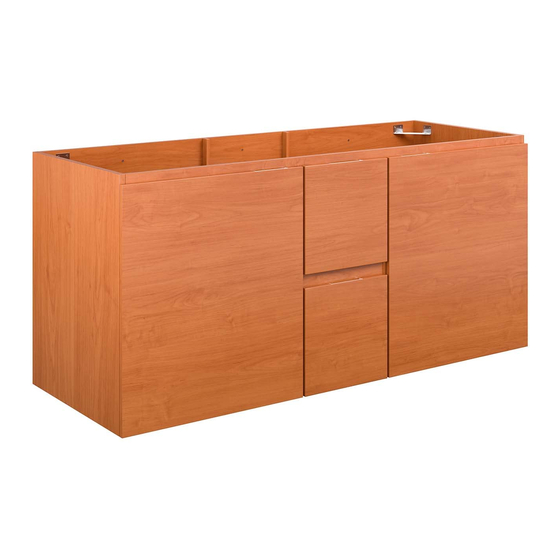
Summary of Contents for modway EEI-5883
- Page 1 A S S E M B LY I N S T R U C T I O N S EEI−5883 V1.01.24.22 Questions? Contact us! 609.256.9000 • cs@modway.com www.modway.com 780−595MD1−0...
-
Page 2: What You Need
+ Level 300mm + Silicone Adhesive or Caulk + Drywall Anchors and Screws Missing parts or hardware? Need assistance? + Other Wall-Mounting Hardware Contact us before returning your item. We're here to help! 609.256.9000 • cs@modway.com PAGE 2 OF 16 780−595MD2−0... - Page 3 Wood Dowel M8 x 25mm Wood Dowel M6 x 25mm Back Panel 1 Bottom Cam Bolt Ø6 x 24mm Front Front Bottom 7 x 2 PAGE 3 OF 16 780−595MD3−0...
- Page 4 Front Bearing Runner 350mm x1 Pair Front Bearing Runner 300mm x1 Pair Screw 4 x 12mm Divider Panel R Spring clip Cam Lock Ø12 PAGE 4 OF 16 780−595MD4-0...
- Page 5 Screw 9 x 38mm PAGE 5 OF 16 780−595MD5−0...
- Page 6 Front Front Bearing Runner 350mm x1 Pair Bearing Runner 300mm x1 Pair Screw 4 x 12mm Drawer Side R 1 Cam Lock Ø15 PAGE 6 OF 16 780−595MD6−0...
- Page 7 Adjust Barrel Nut (R) by using screwdriver if necessary ! Hole Screw 9 x 38mm Direction Screw 6 x 70mm Barrel Nut Hex Wrench Screw 9 x 38mm PAGE 7 OF 16 780−595MD7−0...
- Page 8 Cam Lock Ø15 Cam Lock Ø15 PAGE 8 OF 16 780−595MD8−0...
- Page 9 Shelf Support Screw 9 x 38mm Shelf Panel 1 Shelf Panel 2 PAGE 9 OF 16 780−595MD9−0...
- Page 10 Screw 4 x 14mm Corner Bracket Right Side Panel Back Panel 1 Front Rail 1 Bracket-L/Hanger Bracket-R/Hanger Screw 4 x 28mm PAGE 10 OF 16 780−595MDA-0...
- Page 11 Wall Bracket Installation Guide 18.1 Use a drill to make all pilot holes. 18.2 Insert a Drywall Anchor Measurement Guide into each of the nine holes. All units are in millimeters. WALL 18.3 Install bracket with 3 screws. 18.4 Ensure your bracket measurements are correct Repeat with other brackets.
- Page 12 NOTE: Mounting hardware and tools are not included. We suggest professional installation. Hole = Ø PAGE 12 OF 16 780−595MDC-0...
- Page 13 Screw 4 x 14mm Door Hinge Sold separately Screw 4 x 14mm Rubber Pad Adjust the hinges, if required. Adjust laterally Adjust height Adjust depth Temporarily remove/dismantle the Door & Shelf during Basin/Sink /Plumbing work installation work to prevent water damage. PAGE 13 OF 16 780−595MDD−0...
- Page 14 The drawer(s) can be removed, if ever required. Locate the spring clip on both sides on the drawer glide. At the same time, press the clips and pull the drawer out. To reinsert, simply align the 2 sides of the drawer glides and slide in until fully inserted.
- Page 15 Your sink basin comes complete with a silver overfl ow ring. If you'd like to remove this overfl ow ring, you can do so by hand. Missing parts or hardware? Need assistance? Contact us before returning your item. We're here to help! 609.256.9000 • cs@modway.com PAGE 15 OF 16 780−595MDF−0...
-
Page 16: Connect With Us
Clean using a non-abrasive cloth and a mild cleaner. Never use harsh chemicals, as they could damage the fi nish or integrity of the item. CONNECT WITH US! Tag us @modway_furniture and #modway for a chance to be featured. PAGE 16 OF 16 780−595MDG−0...


Need help?
Do you have a question about the EEI-5883 and is the answer not in the manual?
Questions and answers