Advertisement
Quick Links
PK-93182-10-00-2B
WARNINGS:
• To be installed and/or used in accordance with appropriate electrical codes and regulations.
• If you are unsure about any part of these instructions, consult a qualified electrician.
• To avoid overheating and possible damage to this device and other equipment, do not install to
control a receptacle, fluorescent lighting, a motor- or a transformer-operated appliance.
• Use with incandescent or 120V halogen fixtures only.
Tools needed to install your Dimmer:
Slotted/Phillips Screwdriver
Electrical Tape
Pliers
Pencil
Cutters
Ruler
Color Change Option:
If a color change kit is provided with your device, proceed with the
following step if you need to change the color. Otherwise, proceed with
the "Installing Dimmer by itself or with other devices" section.
Changing the color of your Dimmer
Your Dimmer includes color options. To change color of frame, proceed
as follows:
Push in side at tab
to release
Move the slider up or down one full cycle to automatically engage the
slider control mechanism.
Installing Dimmer by itself or with other devices:
If installing Dimmer in a single device application, proceed with the
INSTALLING YOUR DIMMER section. If installing Dimmer in a multi-
device application, proceed as follows:
MULTI-DEVICE APPLICATION
NOTE: You only need to remove side sections if installing with other
dimmers or if it does not fit in wall box – not when installing with
mechanical switches.
Remove
all inner
side
sections
Do not
remove
outer
side
sections
Bend back and
forth to remove side section
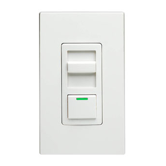
Single Pole (One location) or 3-Way (Multi-location)
Incandescent Slide Dimmer
When installing more than one dimmer in the same location, the side
sections of the mounting strap must be removed. Use pliers to carefully
bend side sections back and forth until they break off. The side sections
dissipate heat, so removing them requires a derating of the dimmer's
capacity (refer to chart).
MAXIMUM LOAD PER DIMMER FOR MULTI-DEVICE
Cat. No.
IPIØ6-1L
IPI1Ø-1L
INSTALLING YOUR DIMMER
NOTE: Use check boxes
WARNING:
Step 1
POWER at circuit breaker or fuse and test that power is off
before wiring!
OFF
Line up tabs and press
OFF
in side to attach
OFF
OFF
OFF
OFF
Removing existing switch:
Step 2
wallplate and switch mounting screws. Carefully pull switch
from wall box. DO NOT remove wires attached to the switch
at this time.
Identifying your wiring application (most
Step 3
common):
NOTE: If the wiring in the wall box does not resemble any of
these configurations, consult a qualified electrician.
Cat. No. IPIØ6-1L, 600W (Lighted)
Cat. No. IPI1Ø-1L, 1000W (Lighted)
120VAC, 60Hz
INSTALLATION INSTRUCTIONS
CAUTIONS:
• Use only one (1) dimmer in a 3- or 4-way circuit. The switch(es) will turn the light on at the brightness
level selected at the dimmer.
• Disconnect power at circuit breaker or fuse when servicing fixture.
• Use this device only with copper or copper clad wire. With aluminum wire use only devices marked
CO/ALR or CU/AL.
More than
Single
Two Devices
2 Devices
600W
500W
400W
1000W
800W
700W
√
when Steps are completed.
To avoid fire, shock, or death; TURN OFF
ON
OFF
ON
OFF
ON
ON
OFF
ON
ON
ON
OFF
ON
ON
OFF
ON
ON
OFF
ON
Remove existing
Step 3
cont'd
Single-Pole:
3-Way:
Look at the back of your switch.
Look at the back of your switch.
If there are 2 wires connected to
If there are 3 wires connected to
two screw terminals (not
three screw terminals (not
including a green or bare copper
including a green or bare copper
wire used for grounding), you
wire used for grounding), you
have a Single-Pole switch.
have a 3-Way switch. Note that
one of the screw terminals will
usually be a different color
(black) or labeled Common. Tag
that wire with electrical tape to
identify.
Disconnecting switch wires and preparing wires:
Step 4
• Disconnect wires from screw terminals or
Quickwire™ slots (shown).
• Pull off pre-cut insulation from Dimmer leads.
• Make sure that the ends of the wires from the
wall box are straight (cut if necessary) .
• Remove 5/8" (1.6 cm) of insulation from each
wire in the wall box (shown).
• For Single-Pole Application, go to Step 5A.
• For 3-Way Application, go to Step 5B.
Cut
(if necessary)
Press in slot and
pull out wire
Tag Common
Screw Wire
Strip 5/8"
(1.6 cm)
5/8"
(1.6cm)
Strip Gage
Advertisement

Related Manuals for Leviton Decora Illumatech IPI06-1L


Summary of Contents for Leviton Decora Illumatech IPI06-1L
- Page 1 PK-93182-10-00-2B WARNINGS: • To be installed and/or used in accordance with appropriate electrical codes and regulations. • If you are unsure about any part of these instructions, consult a qualified electrician. • To avoid overheating and possible damage to this device and other equipment, do not install to control a receptacle, fluorescent lighting, a motor- or a transformer-operated appliance.
- Page 2 Leviton is not liable for incidental, indirect, special, or consequential damages, including without...
Need help?
Do you have a question about the Decora Illumatech IPI06-1L and is the answer not in the manual?
Questions and answers