
Related Manuals for USA Measurements US-6011 Series


Summary of Contents for USA Measurements US-6011 Series
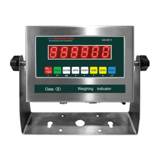
- Page 1 US-6011 SERIES INDICATOR USER’S MANUAL (US-6011SS-4-20MA & US-6011SS-R) usameasurements.com...
-
Page 2: Table Of Contents
Contents DEFINITION OF TERMS ���������������������������������������������������������������������������� 3 SAFETY PRECAUTIONS & MAINTENANCE �������������������������������������������������� 4 PREPARATION & SET UP �������������������������������������������������������������������������� 5 POWER SUPPLY ��������������������������������������������������������������������������������������� 7 DISPLAY AND KEY DESCRIPTION �������������������������������������������������������������� 8 OPERATING INSTRUCTIONS ��������������������������������������������������������������������� 9 CALIBRATION������������������������������������������������������������������������������������������12 INDICATOR PARAMETER SETTINGS ����������������������������������������������������������14 CONNECTORS �����������������������������������������������������������������������������������������21 RS232 SERIAL OUTPUT FORMAT ���������������������������������������������������������������23 US�6011SS�4�20 mA Analog Output ����������������������������������������������������������27 RELAY OUTPUT ���������������������������������������������������������������������������������������29 TROUBLESHOOTING ��������������������������������������������������������������������������������30... -
Page 3: Definition Of Terms
DEFINITION OF TERMS In the context of this guide, the underlisted words are presumed to mean: Division: The amount of increments a scale offers. How accurate the scale can be Capacity: the maximum amount the scale can contain Initial Zero Range: The percentage of weight allowed on the scale when indicator is powered on that will automatically zero. -
Page 4: Safety Precautions & Maintenance
SAFETY PRECAUTIONS & MAINTENANCE WARNING: The use of procedures not specified in this user manual may result in electrical hazards. Follow these instructions when using the weighing indicator: 1. The weighing indicator should be on a stable surface. 2. Do not touch the internal components with your hands 3. -
Page 5: Preparation & Set Up
PREPARATION & SET UP This user manual highlights the basic requirements to enable the smooth operation of the weighed indicator. 1. Plug the scale into a wall socket to avoid interference with other electrics. 2. Ensure there is no load when the indicator is turned on. 3. - Page 6 Technical Considerations • Accuracy class: 5000 e • Excitation circuit: 5 VDC, 4 wire connection, 6 load cell of 350ohm max • Resolution – Display: 30,000 ; ADC: 2,000,000 • AC power: AC 100-250V (use only the included 9V adapter supplied) •...
-
Page 7: Power Supply
POWER SUPPLY The indicator has a 110V power adapter with an option to use the rechargeable battery at one’s convenience. When using the power adapter: It is recommended that the power adapter should be plugged into a wall socket to avoid interference with other electrics. -
Page 8: Display And Key Description
DISPLAY AND KEY DESCRIPTION DISPLAY DESCRIPTION FUNCTION ON/OFF Press for 2 seconds, to on or off the indicator HOLD TOTAL 1. accumulates weights 2. performs the accumulation function and accumulation result, alongside the “Print” function. UNITS Indicates changes in weighing units COUNT To count products based on a sample weight, use the scale. -
Page 9: Operating Instructions
OPERATING INSTRUCTIONS Power On • Press the “ON/OFF” button for 20 seconds to power the scale ON. The scale will automatically flash the voltage and auto-check. It performs a sequential countdown from 0 to 9 before entering the weighing mode. The Scale also tares out anything on it before powering on. - Page 10 After pressing the PRINT button, you can load the product on the scale. • The indicator will show the product quantity on display. Press the COUNT button to exist the counting mode. If you want to determine the quantity of a different product hold the PRINT and COUNT key together and the sample pieces will reset back to zero.
- Page 11 4. Average Hold: It is used for weighing animals, the indicator will display the average weight sampled from 3 seconds • Add livestock to scale and press HOLD • Indicator screen will show “LOC” for 3 seconds, then display the average weight from those 3 seconds •...
-
Page 12: Calibration
CALIBRATION 1. Turn on the scale by holding ON/OFF for 2 seconds. 2. Press HOLD and PRINT together to access the setup menu. 3. If done correctly, the display should now show C01. 4. Press PRINT to access the C1 channel. The display should show [C1 #]. 5. - Page 13 To Calibrate using only 1 calibration weight (Single Point Calibration) 1. Press PRINT to continue. The display will now show C06. 2. Press PRINT to access the C06 channel. The display will show [C6 0]. 3. The C6 channel is used to calibrate the scale with a known weight. 4.
-
Page 14: Indicator Parameter Settings
INDICATOR PARAMETER SETTINGS The parameter settings menu has a calibration section (C01 to C07 explained above) and a parameter settings section (C08 and up). To access the calibration section the seal switch (located at one corner of the PCB) must be OFF. This will allow access to all C01 and up settings. - Page 15 Calibration 0 = calibration not needed 1 = Ready to calibrate with one calibration weight 2= Ready to calibrate using multiple calibration weights (Linear) 3 = Sensitivity Output Restore Default Settings 0 = do not restore 1 = restore to default settings Warning Tone 0 = turn off warning tone 1 = turn on warning tone...
- Page 16 Communication Setting Set the serial interface data output method: 0 = Turn off serial interface data output 1 = Continuous sending mode, for remote display 2 = Print to paper thermal ticket printer 3 = Command request mode, for computer. 4 = PC continuous sending mode, for computer 5 = PC/remote display, continuous sending...
- Page 17 Zero Tracking 0= turn off zero tracking d = division 0.5 = ±0.5d 1.0 = ±1.0d 2.0 = ±2.0d 3.0 = ±3.0d 4.0 = ±4.0d 5.0 = ±5.0d Note: the zero tracking range can not be bigger than manual zero range Zero Tracking Time 0 = turn off zero tracking time 1 = 1 second 2 = 2 seconds...
- Page 18 Noise Filter 0 = turn off noise filter 1 = 1 digital filter strength 2 = 2 digital filter strength 3 = 3 digital filter strength Print Time and Date 0 = yy.mm.dd 1 = mm.dd.yy 2 = dd.mm.yy 3 = yy.mm.dd Analog Output Setting 0=0-5Vouput 1 = 4 - 20mA output...
- Page 19 Table 2. Unit Conversion Parameter Settings Parameter Settings Units Available C01=3&C12=0 gram only C01=4&C12=0 oz only C01=1&C12=0 kg only C01=1&C12=1 kg/lb C01=1&C12=2 kg/lb/oz C01=1&C12=3 kg/lb/lb:oz/oz C01=1&C12=4 kg only C01=2&C12=0 lb only C01=2&C12=1 lb/kg C01=2&C12=2 kg/lb/oz C01=2&C12=3 kg/lb/lb:oz/oz C01=3&C12=4 lb only Table 3.
- Page 20 Digital Filter Noise Filter Print Time and Date Analog Output Setting Calibrate Current Relay Output Setting Multi-connection add. Wireless Communication Wireless Communication 9.7936 Gravity of Destination 9.7936 Page 20...
-
Page 21: Connectors
CONNECTORS Connecting load cells to the indicator • The indicator can connect with 6 load cells of 350Ω at most • 4 wire or 6 wire load cell connections are both okay • Please contact us directly if you have other special needs for your application There are two connection methods between the load cell and indicator Quick Disconnect as shown below: Hardwire (Using Inner Terminal Block Connection:... - Page 22 Table 4. Wiring Color Code Signal Name Color Code Description +Exe/ +EX Positive excitation voltage to load cell +IN / +SIG GREEN Positive output signal from load cell HD / SHLD YELLOW/THICK BLACK Shield Wire -IN / -SIG WHITE Negative output signal from load cell -EXC / -EX BLACK...
-
Page 23: Rs232 Serial Output Format
RS232 SERIAL OUTPUT FORMAT When connecting the indicator to the RS-232 Serial device, follow the pin out of Table 5 below. Table 5. DB9 Pin Description DB9 Pin Definition Definition Transmit Data Receive Data Ground Interface The serial output format depends on the settings for parameter C18. The serial output consists of a string of ASCII characters. - Page 24 Output Continuous Format State A Bits 0, 1,2 Decimal point position XXXXXX0 XXXXXXX XXXXX.X XXXX.XX XXX.XXX Bits3,4 Satate B BitsS function Bits0 gross=0, net=1 Bits1 Symbol: positive=0, negative=1 Bits2 Overload (or under zero)=1 Bits3 dynamic=1 Bits4 unit: lb=0, kg=1 Bits5 Constant 1 State C Bit2...
- Page 25 Print Mode (C18 = 2) For printing on a non-adhesive ticket printer. Parameters 16, 17, 30, & 42-45 all effect your ticket print out. Normal weighing ticket printout example: Date: 05/01/2017 Time: 11:30:52 Net: 25.6Ib Tare: 10.3Ib Gross: 35.9Ib Accumulation weighing ticket printout example: Date: 05/01/2017 Time:...
- Page 26 Computer Continuous Sending Mode (C18=4) Data Symbol Interpretation S1: weight status, ST=standstill, US=not standstill, OL=overload S2: weight mode, GS=gross mode, NT=net mode S3: weight of positive and negative, “+” or “-” Data: weight value, including decimal point S4: “kg” or “lb” CR: carriage return LF: line feed PC or Remote Display Continuous Sending Mode (C18=5) <STX>...
-
Page 27: Us-6011Ss-4-20 Ma Analog Output
US-6011SS-4-20 mA Analog Output The US-6011SS-4-20-mA analog output is a voltage sourcing sensor that outputs current proportional to the weight range of the calibrated scale (i.e. 4 mA = 0 LBS and 20 mA = 10,000 LBS). It is a sensor with a sourcing output (i.e. the sensor will source 9VDC with an output current range of 4-20 mA). - Page 28 Calibration: Press PRINT and HOLD key to go into configuration mode • Go to C32 and press PRINT key • The display should show [out�4] and output should be at 4mA • Press the up/down arrow keys and the [out�#] will increase/decrease •...
-
Page 29: Relay Output
RELAY OUTPUT The indicator can output 4 signals, which when connected to outside equipment, can perform an automatic control function and an upper/lower limit alarm function. You can change parameter setting C33 following Table 6 below: Table 6: Relay Output Parameter Setting Output Port Definition Function... -
Page 30: Troubleshooting
TROUBLESHOOTING Error Codes Reason Solution 1. Overload 1. Reduce the weight 2. Wrong connection with 2. Check load cell connection load cell 3. Inspect load cell; Check the 3. Load cell has quality input/output problem UUUUUU 4. See Q&A section Calibration is no good 1. -
Page 31: Faqs
FAQs Q: The scale does not turn on Ensure that your cord is properly plugged into the wall socket when there is power supply. Confirm that there is power supply. One easy way to test this is by connecting another appliance to the same outlet and see if it is working. Q: The reading goes negative when a load is applied Try interchanging the Sig+ and Sig- wiring connected to the load cell and/or junction box one is used) - Page 32 You can send an email to sales@usameasurements.com for any questions about your sales or support. Alternatively, call 800-711-2237. for sales and support. Visit our website at: usameasurements.com...
Need help?
Do you have a question about the US-6011 Series and is the answer not in the manual?
Questions and answers