Advertisement
Quick Links
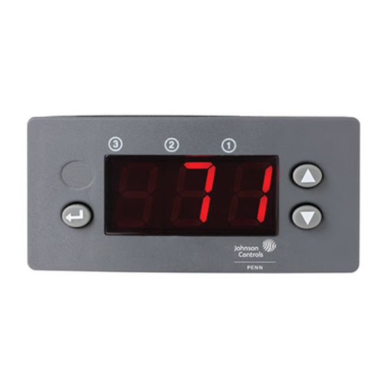
MR2 Refrigeration Temperature/Defrost Control
IMPORTANT:
All MR2 controls are designed for
use only as operating controls.
Where an operating control
failure would result in personal
injury or loss of property, it is the
responsibility of the installer to
add devices (safety, limit
controls) or systems (alarm,
supervisory systems) that protect
against, or warn of, control
failure.
Refer to the MR Series Refrigeration Temperature
Controls Product Bulletin, LIT-125199, for necessary
information on operation and performance
specifications for this product.
M
ounting
The MR2 Control is not position-sensitive but should
be mounted for convenient wiring and adjustment.
To mount the Panel Mount version, ensure that there
is a space of at least 2-3/4 in. (70 mm) behind the
panel. Make a cutout 1-3/16 x 2-13/16 in.
(29 x 71 mm). Remove retaining clip from the control.
Insert the control into the hole. Install retaining clip and
adjust for tightness.
To mount the DIN Rail Mount version, install the DIN
rail where appropriate. Snap the control onto the rail in
position.
W
iring
!
WARNING: Shock Hazard. To avoid
possible electrical shock or
equipment damage, disconnect
power supply before wiring any
connections.
© 1999 Johnson Controls, Inc.
Part No. 24-7664-1695, Rev. A
Code No. LIT-125194
I
B
NSTALLATION
ULLETIN
Follow these wiring guidelines:
All wiring must conform to the National Electric
Code and local regulations.
Make all wiring connections using adequate gauge
copper conductors only. Connectors are rated for
14-22 AWG wiring.
C
anadian DOC Compliance
This digital apparatus does not exceed the Class A
limits for radio noise emissions from digital apparatus
set out in the Radio Interference Regulations of the
Canadian Department of Communications.
Temperature Controls Section A
Installation Bulletin
Sensor
Common
Process
Binary
Temperature
Input
Binary
Sensor
Common
S1 SC
D CD
Terminal Not Used
V1 V2
C
Fr
Refer to Rating Table
for more information.
Power
Compressor
Supply
Figure 1: MR2 DIN Rail Control
Internal to Control
A2
C
Fr
A1
V1 V2
Compressor
Alarm
Power
Supply
Refer to Rating Table
Binary
for more information.
Input
Figure 2: MR2 Panel Mount Control
FANs 125, 121
Issue Date 1199
Alarm
A1
A2
Internal to Control
Terminal Not Used
D SC S1
Sensor
Common
Process
Temperature
Sensor
1
www.johnsoncontrols.com
Advertisement

Subscribe to Our Youtube Channel
Related Manuals for Johnson Controls MR2


Summary of Contents for Johnson Controls MR2
- Page 1 Refer to Rating Table ounting for more information. Power Compressor The MR2 Control is not position-sensitive but should Supply be mounted for convenient wiring and adjustment. Figure 1: MR2 DIN Rail Control To mount the Panel Mount version, ensure that there is a space of at least 2-3/4 in.
- Page 2 After 10 seconds of inactivity, the display will return to its normal function. Note: If the Enter button is not pressed after selecting the new value, the new value is not saved. The control reverts to the previous value. A—MR2 Refrigeration Temperature/Defrost Control Installation Bulletin...
- Page 3 When contacting the supplier for replacement, state case of a defective or improperly functioning control, the model number of the control. This number can check with your nearest Johnson Controls/PENN be found on the data plate. representative. A—MR2 Refrigeration Temperature/Defrost Control Installation Bulletin...
- Page 4 The performance specifications are nominal and conform to acceptable industry standards. For application at conditions beyond these specifications, consult Johnson Controls/Penn Refrigeration Application Engineering at (414) 274-5535. Johnson Controls, Inc. shall not be liable for damages resulting from misapplication or misuse of its products.
Need help?
Do you have a question about the MR2 and is the answer not in the manual?
Questions and answers