Table of Contents
Advertisement
Quick Links
INSTALLATION INSTRUCTIONS
Pulse Energy Meter
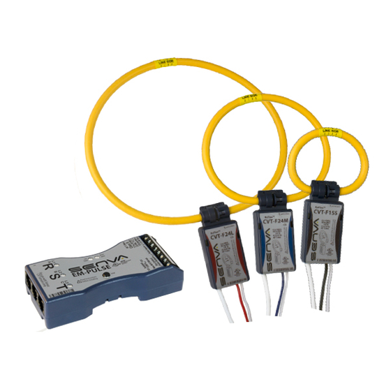
EM-PULSE and Current/Voltage Transducers
The EM-PULSE is a three channel meter, capable of monitoring
single-phase, two-phase and three-phase systems, as well
as 3 independent single-phase systems with one meter. The
EM-PULSE meter offers 2 pulse outputs and 2 pulse inputs
to maintain flexibility during installation and operation. The
EM-PULSE is compatible with all sizes of current/voltage
transducers (CVTs). With the meter's AutoScale feature, the
pulse scale is set according to the CVT amperage, removing
the need for manual configuration.
Each CVT is independently calibrated to measure and digitally
communicate power values with the meter. The CVT's flexible
rogowski coil makes installations less burdensome. To maintain
high accuracy and flexibility for multiple channel installs, high
voltage connections are made directly into each CVT. Each
CVT is rated for installations ranging from 90 to 600V.
DANGER
HAZARD OF ELECTRIC SHOCK, EXPLOSION, OR ARC FLASH
Failure to follow these instrutions may cause serious injury or death
•
Read, understand and follow the instructions before installing this
product.
•
The high voltage CVTs of this product must be mounted inside a
suitable fire and electrical enclosure. Follow safe electrical work
practices. See NFPA 70E in the USA, or applicable local codes.
•
This equipment must only be installed and serviced by qualified
electrical personnel having the skills and knowledge related to
the construction and operation of this electrical equipment and
installation, and has received safety training to recognize and
avoid the hazards involved. NEC Article 100.
•
Do not use this product for life or safety applications.
•
Do not install this product in hazardous or classified locations.
•
Product may use multiple voltage/power sources. Disconnect ALL
sources before servicing.
•
Use a properly rated voltage sensing device to confirm that
DANGER
power is off. DO NOT depend on this product for voltage
indication.
•
Replace all doors, covers and protective devices before powering
the equipment.
•
The installer is responsible for conformance to all applicable
codes.
!
WARNING
Failure to follow these instructions may cause injury, death or
equipment damage.
•
The EM-RS485 and CVT sensors are designed to be used as a
system. DO NOT connect anything other than a Senva CVT sensor
to the RJ-11 jacks on the meter base.
•
If product is used in a manner not specified by the manufacturer,
the protection provided by the product may be impaired.
No responsibility is assumed by the manufacturer for any
consequences arising out of the use of this material.
WARRANTY DISCLAIMER
DO NOT modify the length of the CVT Data Communication Cable.
Field modifications to the CVT Data Communication Cable will void
factory warranty.
LET'S GET STARTED!
Product Descriptions (page 2)
▪
EM-PULSE product diagram
▪
Current/Voltage Transducer (CVT) diagram
Mounting (page 2)
▪
Versatile mounting options for EM-PULSE
▪
Recommended mounting for maximum CVT accuracy
Wiring (page 3)
▪
Typical single-phase and three-phase systems
▪
Output wiring options
▪
Input wiring options
Normal Operation Mode (page 4)
▪
LED indicators for Normal, Warning, and Error conditions
Diagnostics Mode (page 4)
▪
Diagnostic Mode and Diagnostic Codes
Default Settings (page 5)
Configuration Settings (pages 5-6)
▪
Pulse Scale
▪
Pulse/Alarm Options
▪
Energy Output Types
▪
Balanced Load Multiplier
▪
PowerPrint Power Quality Alarm
View and Edit Settings (pages 7-8)
▪
View Settings Mode
▪
Edit Settings Mode
Specifications (page 9)
Higher Reliability, Faster Installation, Superior Accuracy | Sense the difference |
NEED HELP? Call 1-866-660-8864
1
Advertisement
Table of Contents

Subscribe to Our Youtube Channel
Related Manuals for senva EM Pulse Series


Summary of Contents for senva EM Pulse Series
- Page 1 ▪ Edit Settings Mode • The EM-RS485 and CVT sensors are designed to be used as a system. DO NOT connect anything other than a Senva CVT sensor Specifications (page 9) to the RJ-11 jacks on the meter base. •...
- Page 2 The EM-PULSE features four mounting options for convenience: and two pulse outputs. The EM-PULSE supports the use of all rare-earth magnets, mounting tabs, horizontal DIN rail and Senva Current Voltage Transducers (CVTs), interchangeably. vertical DIN rail. The EM-PULSE meter base is a class 2 low voltage device for mounting flexibility.
- Page 3 NEED HELP? Call 1-866-660-8864 PULSE OUTPUT WIRING OPTIONS Wiring The four diagrams below detail wiring for common installation configurations. Provide a disconnect device to disconnect the meter from the supply source. In the US and Canada, disconnecting fuse Net Import and Export Energy holders or circuit breakers can be used.
-
Page 4: Normal Operation Mode
Low supply voltage Increase meter supply voltage Temperature warning Relocate meter to suitable Setup Button environment If code is not shown in table above, please contact Senva technical support: support@senvainc.com or (866) 660-8864 | 866-660-8864 | fax 503-296-2529 | www.senvainc.com... -
Page 5: Default Settings
NEED HELP? Call 1-866-660-8864 Default Settings Configuration Settings The EM-PULSE meter allows for manual configuation of the The EM-PULSE installs with minimal user intervention. following settings: If LEDs are green and you are happy with default factory settings Pulse Scale below, your installation is complete! Pulse/Alarm Options Energy Output Type... - Page 6 Alarm Mode: Output 2 provides a normally open alarm output. PowerPrint can only learn and save characteristics for channels The default alarm is for phase loss of one or more channels with a properly installed CVT. If the CVT is displaying a in a multi-phase installation.
- Page 7 NEED HELP? Call 1-866-660-8864 View and Edit Settings To view and edit the settings on the EM-PULSE meter, proceed through the steps below for manual configuration with the setup button and LEDs. View Settings Mode Flowchart STEP 1 STEP 4 STEP 5 CVT Status LEDs R S T...
- Page 8 View/Edit Settings Mode Flowchart STEP 1 STEP 6 NORMAL VIEW SETTINGS MODE STEP 5 MODE Setting 1 Setting 2 Setting 3 Setting 4 Setting 5 Balanced Pulse/Alarm Pulse Scale Energy Type PowerPrint Load Options STEP 2 Multiplier CVT Status LEDs R S T STEP 3 EDIT SETTINGS MODE...
-
Page 9: Specifications
NEED HELP? Call 1-866-660-8864 Specifications Power Supply Input 12-30VDC/24VAC , 1.5W Max, 100mA Max Dual Outputs Import & Export Energy Outputs Type Solid state dry contact Pulse Outputs Specifications N.O., 300mA max, 40V max Pulse scaling 0.01, 0.1, 1, 10, 100, 1k Wh/Pulse Conductor gage 14-26 AWG Wiring Requirements Terminal torque rating 0.4 ft-lb (0.55 N-m)
Need help?
Do you have a question about the EM Pulse Series and is the answer not in the manual?
Questions and answers