senva EM-RS485 Installation Instructions Manual
Protocol energy meter
Hide thumbs
Also See for EM-RS485:
- Protocol manual (52 pages) ,
- Installation instructions manual (10 pages)
Table of Contents
Advertisement
Quick Links
INSTALLATION INSTRUCTIONS
Protocol Energy Meter
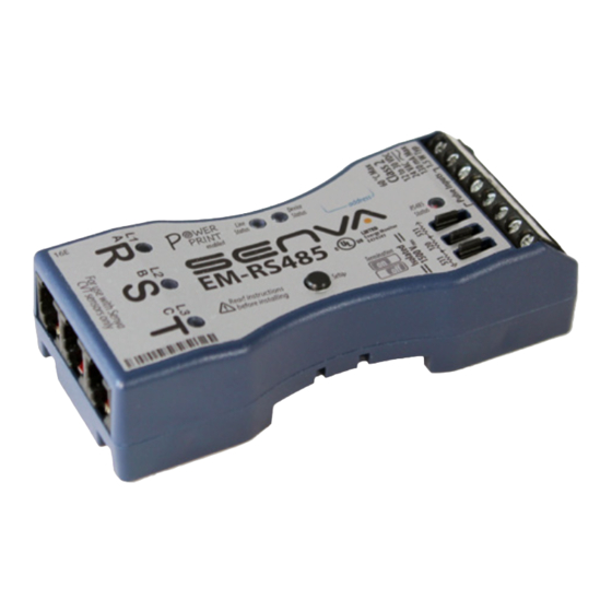
EM-RS485 and Current/Voltage Transducers
The EM-RS485 is a three channel meter, capable of monitoring
single-phase, two-phase and three-phase systems, as well
as 3 independent single-phase systems with one meter.
The EM-RS485 meter offers BACnet MS/TP and Modbus RTU
protocols and 2 pulse inputs to maintain flexibility during
installation and operation. The EM-RS485 is compatible with
all sizes of current/voltage transducers (CVTs). With the EM-
RS485 intelligent meter technology, the device self-configures
baud rate, serial format, protocol, and address (BACnet only) -
eliminating additional configuration steps.
Each CVT is independently calibrated to measure and digitally
communicate power values to the meter. The CVT's flexible
Rogowski coil makes installations less burdensome. The
voltage connections are made directly into each CVT - keeping
all high voltage away from the meter. Each CVT is rated from 90
to 600VAC.
DANGER
HAZARD OF ELECTRIC SHOCK, EXPLOSION, OR ARC FLASH
Failure to follow these instrutions may cause serious injury or death
•
Read, understand and follow the instructions before installing this
product.
•
The high voltage CVTs of this product must be mounted inside a
suitable fire and electrical enclosure. Follow safe electrical work
practices. See NFPA 70E in the USA, or applicable local codes.
•
This equipment must only be installed and serviced by qualified
electrical personnel having the skills and knowledge related to
the construction and operation of this electrical equipment and
installation, and has received safety training to recognize and
avoid the hazards involved. NEC Article 100.
•
Do not use this product for life or safety applications.
•
Do not install this product in hazardous or classified locations.
•
Product may use multiple voltage/power sources. Disconnect ALL
sources before servicing.
•
Use a properly rated voltage sensing device to confirm that
DANGER
power is off. DO NOT depend on this product for voltage
indication.
•
Replace all doors, covers and protective devices before powering
the equipment.
•
The installer is responsible for conformance to all applicable
codes.
!
WARNING
Failure to follow these instructions may cause injury, death or
equipment damage.
•
The EM-RS485 and CVT sensors are designed to be used as a
system. DO NOT connect anything other than a Senva CVT sensor
to the RJ-11 jacks on the meter base.
•
If product is used in a manner not specified by the manufacturer,
the protection provided by the product may be impaired.
No responsibility is assumed by the manufacturer for any
consequences arising out of the use of this material.
WARRANTY DISCLAIMER
DO NOT modify the length of the CVT Data Communication Cable.
Field modifications to the CVT Data Communication Cable will void
factory warranty.
LET'S GET STARTED!
Product Descriptions (page 2)
▪
EM-RS485 product diagram
▪
Current/Voltage Transducer (CVT) diagram
Mounting (page 2)
▪
Mounting options for EM-RS485
▪
Recommended mounting for maximum CVT accuracy
Wiring (page 3)
▪
Typical single-phase and three-phase systems
▪
Communication wiring options
▪
Input wiring options
Normal Operation (page 4)
▪
LED indicators for Normal, Warning, and Error conditions
▪
Restore Factory Default Settings
Diagnostics (page 4)
▪
Diagnostic Mode and Diagnostic Codes
Network Connectivity (pages 5-6)
Configuration Settings (page 7)
▪
Address Assignment
▪
Protocol Type Configuration
▪
Baud Rate Configuration
▪
Serial Format Configuration
▪
PowerPrint Power Quality Alarm
View and Edit Settings (pages 8-9)
▪
View Settings Mode
▪
Edit Settings Mode
Specifications (page 10)
SUPPORTING DOCUMENTS
EM BACnet Protocol Guide
▪
www.senvainc.com/emrs485bn
EM Modbus Protocol Guide
▪
www.senvainc.com/emrs485mb
Higher Reliability, Faster Installation, Superior Accuracy | Sense the difference |
NEED HELP? Call 1-866-660-8864
1
Advertisement
Table of Contents

Related Manuals for senva EM-RS485


Summary of Contents for senva EM-RS485
- Page 1 Failure to follow these instructions may cause injury, death or equipment damage. • The EM-RS485 and CVT sensors are designed to be used as a SUPPORTING DOCUMENTS system. DO NOT connect anything other than a Senva CVT sensor to the RJ-11 jacks on the meter base.
- Page 2 Mounting EM-RS485 Meter Mounting Options The EM-RS485 is a 3 channel energy meter which supports The EM-RS485 features four mounting options for convenience: both BACnet MS/TP and Modbus RTU protocols. The meter rare-earth magnets, mounting tabs, horizontal DIN rail and also includes 2 pulse inputs that can connect to a variety vertical DIN rail.
- Page 3 Wiring Use the jumpers to select the 120 ohm EOL resistor if the Senva EM-RS485 meter is the last device in your network. If the meter is being installed within a network of other Provide a disconnect method to disconnect the meter from existing RS485 devices, it may be necessary to use the 510 the supply source.
-
Page 4: Normal Operation Mode
Setup Button Temperature warning Relocate meter to suitable environment Diagnostic Mode is only available if any LEDs display If code is not shown in table above, please contact Senva technical support: yellow or red in Normal Operation Mode. ... -
Page 5: Network Connectivity
The EM-RS485 installs with minimal user configuration. The EM-RS485 is designed for use on both BACnet and Modbus networks. The meter is designed to automatically identify the network baud rate, protocol type, serial formats and self-address (BACnet only) for quick startup. - Page 6 Network Activity Diagnostic Mode Navigation Flowchart Once the EM-RS485 meter is properly configured to a network, the RS485 LED y will blink remain blinking green Normal Operation Mode: NORMAL MODE If any LEDs display yellow or red, a in response to network activity. If the RS485 LED appears ...
-
Page 7: Configuration Settings
Normal Operation, take configuration. the corrective action to resolve the installation error prior to BACnet: If the EM-RS485 is connected to a BACnet network, enabling PowerPrint. the meter will analyze the network traffic to detect an unused PowerPrint can be enabled through Section 8 - View/Edit MAC address. - Page 8 View and Edit Settings To view and edit the settings on the EM-RS485 meter, proceed through the steps below for manual configuration with the setup button and LEDs. For more advanced configuration, refer to the EM BACnet Protocol Guide or EM Modbus Protocol Guide documents.
- Page 9 Edit Setting Settings section to assist in working through Steps 1-6 to The current setting will be displayed on the CVT LEDs in navigate the Edit Settings Mode in the EM-RS485 meter: yellow (representing Edit Mode). Press the Setup Button ...
-
Page 10: Specifications
Specifications Power Supply Input 12-30VDC/24VAC , 1.5W max,100mA max. RS-485 2-wire, BACnet MS/TP, Modbus RTU, Modbus ASCII Output Baud Rates 9600, 19200, 38400, 57600, 76800, 115200 RS-485 Loading 1/4 unit Conductor gauge 14-26 AWG Wiring Requirements Terminal torque rating 0.4 ft-lb (0.55 N-m) Input Rating 3.5 +/- 0.5 VDC, short circuit current is 10mA max Pulse Rate 50 Hz (default), configurable up to 500 Hz Pulse Inputs...
Need help?
Do you have a question about the EM-RS485 and is the answer not in the manual?
Questions and answers