Euresys eGrabber 1629 Coaxlink Duo PCIe/104-EMB Hardware Manual
Hide thumbs
Also See for eGrabber 1629 Coaxlink Duo PCIe/104-EMB:
- Hardware manual (234 pages) ,
- Installation manual (4 pages) ,
- Installation manual (3 pages)
Table of Contents
Advertisement
Quick Links
eGrabber
Frame Grabbers Hardware Manual
1629 Coaxlink Duo PCIe/104-EMB
1630 Coaxlink Mono
1631 Coaxlink Duo
1632 Coaxlink Quad
1633 Coaxlink Quad G3
1633-LH Coaxlink Quad G3 LH
1635 Coaxlink Quad G3 DF
1637 Coaxlink Quad 3D-LLE
3602 Coaxlink Octo
© EURESYS S.A. 2022 - Doc. D205ET-Frame Grabbers Hardware Manual-eGrabber-22.08.2.2171 built on 2022-
HARDWARE MANUAL
3603 Coaxlink Quad CXP-12
3603-4 Coaxlink Quad CXP-12
3620 Coaxlink Quad CXP-12 JPEG
3620-4 Coaxlink Quad CXP-12 JPEG
3621 Coaxlink Mono CXP-12
3621-LH Coaxlink Mono CXP-12 LH
3622 Coaxlink Duo CXP-12
3622-LH Coaxlink Duo CXP-12 LH
3625 Coaxlink QSFP+
Advertisement
Table of Contents

Related Manuals for Euresys eGrabber 1629 Coaxlink Duo PCIe/104-EMB


Summary of Contents for Euresys eGrabber 1629 Coaxlink Duo PCIe/104-EMB
- Page 1 1633-LH Coaxlink Quad G3 LH 3622 Coaxlink Duo CXP-12 1635 Coaxlink Quad G3 DF 3622-LH Coaxlink Duo CXP-12 LH 1637 Coaxlink Quad 3D-LLE 3625 Coaxlink QSFP+ 3602 Coaxlink Octo © EURESYS S.A. 2022 - Doc. D205ET-Frame Grabbers Hardware Manual-eGrabber-22.08.2.2171 built on 2022-...
- Page 2 This documentation is provided with eGrabber 22.08.2 (doc build 2171). www.euresys.com This documentation is subject to the General Terms and Conditions stated on the website of EURESYS S.A. and available on the webpage https://www.euresys.com/en/Menu-Legal/Terms-conditions. The article 10 (Limitations of Liability and Disclaimers) and article 12 (Intellectual Property Rights) are more specifically...
-
Page 3: Table Of Contents
eGrabber Hardware Manual Contents 1. Document Scope 2. Mechanical Specification 2.1. Board and Bracket Layouts 1629 Coaxlink Duo PCIe/104-EMB 1630 Coaxlink Mono 1631 Coaxlink Duo 1632 Coaxlink Quad 1633 Coaxlink Quad G3 1633-LH Coaxlink Quad G3 LH 1635 Coaxlink Quad G3 DF 1637 Coaxlink Quad 3D-LLE 3602 Coaxlink Octo 3603 Coaxlink Quad CXP-12 and 3603-4 Coaxlink Quad CXP-12... - Page 4 eGrabber Hardware Manual CoaXPress CXP-12 Host Interface CoaXPress CoF-10 Host Interface 3.2. PCI Express Interfaces 4-lane Rev 2.0 PCIe end-point 4-lane Rev 3.0 PCIe end-point 8-lane Rev 3.0 PCIe end-point 3.3. Power Power Distribution Schemes 1629 Coaxlink Duo PCIe/104-EMB 1630 Coaxlink Mono 1631 Coaxlink Duo 1632 Coaxlink Quad 1633 Coaxlink Quad G3 and 1633-LH Coaxlink Quad G3 LH...
- Page 5 eGrabber Hardware Manual 1625 DB25F I/O Adapter Cable 3303 C2C-Link Ribbon Cable 3304 HD26F I/O Adapter Cable Custom C2C-Link Ribbon Cable Assembly 5.4. Coaxlink Duo PCIe/104 accessories 6. Appendix 6.1. TTL, 5 V CMOS and LVTTL Levels 6.2. Connecting TTL Devices to Isolated I/O Ports TTL And LVTTL Voltage Levels Connecting TTL Devices to Isolated Input Ports Connecting TTL Devices to Isolated Output Ports...
-
Page 6: Document Scope
eGrabber Hardware Manual 1. Document Scope This document describes the hardware specifications of the following main products and their related accessories: Frame Grabbers Product S/N Prefix Camera Interface Icon 1629 Coaxlink Duo PCIe/104-EMB CoaXPress CXP-6 1630 Coaxlink Mono CoaXPress CXP-6 1631 Coaxlink Duo CoaXPress CXP-6 1632 Coaxlink Quad... - Page 7 eGrabber Hardware Manual Accessories Product S/N Prefix Icon 1625 DB25F I/O Adapter Cable 1636 InterPC C2C-Link Adapter 3300 HD26F I/O module for Coaxlink Duo PCIe/104 3301 Thermal drain (Model 1) for Coaxlink Duo PCIe/104 3302 DIN1.0/2.3 Coaxial cable for Coaxlink Duo PCIe/104 3303 C2C-Link Ribbon Cable 3304 HD26F I/O Adapter Cable 3610 HD26F I/O Extension Module - TTL-RS422...
-
Page 8: Mechanical Specification
eGrabber Hardware Manual 2. Mechanical Specification Mechanical specifications of the product(s) including: product pictures, physical dimensions, connectors description and pin assignments, LEDs description, switches description, etc. 2.1. Board and Bracket Layouts 2.2. Camera Connectors 2.3. GPIO Connectors 2.4. Other Connectors 2.5. -
Page 9: Board And Bracket Layouts
eGrabber Hardware Manual 2.1. Board and Bracket Layouts 1629 Coaxlink Duo PCIe/104-EMB 1630 Coaxlink Mono 1631 Coaxlink Duo 1632 Coaxlink Quad 1633 Coaxlink Quad G3 1633-LH Coaxlink Quad G3 LH 1635 Coaxlink Quad G3 DF 1637 Coaxlink Quad 3D-LLE 3602 Coaxlink Octo 3603 Coaxlink Quad CXP-12 and 3603-4 Coaxlink Quad CXP-12 3620 Coaxlink Quad CXP-12 JPEG and 3620-4 Coaxlink Quad CXP-12 JPEG 3621 Coaxlink Mono CXP-12... -
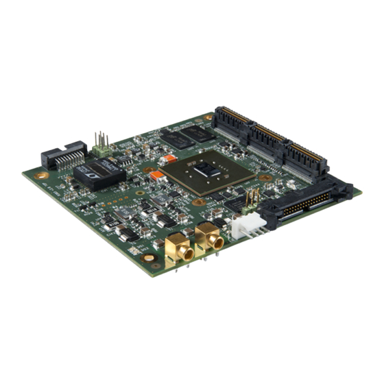
Page 10: 1629 Coaxlink Duo Pcie/104-Emb
eGrabber Hardware Manual 1629 Coaxlink Duo PCIe/104-EMB ● CoaXPress Host A Connector ● "12 V LED " on page 66 ● CoaXPress Host B Connector ● "Board Status LED" on page 67 ● C2C-Link Connector ● "FPGA Status LED" on page 68 ●... -
Page 11: 1630 Coaxlink Mono
eGrabber Hardware Manual 1630 Coaxlink Mono ● "DIN 1 CoaXPress Host Connector" on page 27 ● "CoaXPress LED Lamps" on page 64 ● External I/O Connector ● "Board Status LED" on page 67 ● Internal I/O 1 Connector ● "FPGA Status LED" on page 68 ●... -
Page 12: 1631 Coaxlink Duo
eGrabber Hardware Manual 1631 Coaxlink Duo ● "DIN 2 CoaXPress Host Connector" on page 28 ● "CoaXPress LED Lamps" on page 64 ● External I/O Connector ● "Board Status LED" on page 67 ● Internal I/O 1 Connector ● "FPGA Status LED" on page 68 ●... -
Page 13: 1632 Coaxlink Quad
eGrabber Hardware Manual 1632 Coaxlink Quad ● "DIN 4 CoaXPress Host Connector" on page 30 ● "CoaXPress LED Lamps" on page 64 ● External I/O Connector ● "Board Status LED" on page 67 ● Internal I/O 1 Connector ● "FPGA Status LED" on page 68 ●... -
Page 14: 1633 Coaxlink Quad G3
eGrabber Hardware Manual 1633 Coaxlink Quad G3 ● "DIN 4 CoaXPress Host Connector" on page 30 ● "CoaXPress LED Lamps" on page 64 ● External I/O Connector ● "Board Status LED" on page 67 ● Internal I/O 1 Connector ● "FPGA Status LED" on page 68 ●... -
Page 15: 1633-Lh Coaxlink Quad G3 Lh
eGrabber Hardware Manual 1633-LH Coaxlink Quad G3 LH ● "DIN 4 CoaXPress Host Connector" on page 30 ● "CoaXPress LED Lamps" on page 64 ● External I/O Connector ● "Board Status LED" on page 67 ● Internal I/O 1 Connector ●... -
Page 16: 1635 Coaxlink Quad G3 Df
eGrabber Hardware Manual 1635 Coaxlink Quad G3 DF ● "DIN 4 CoaXPress Host Connector" on page 30 ● "CoaXPress LED Lamps" on page ● "DIN 4 CoaXPress Data Forwarding Connector" on page 31 ● "Board Status LED" on page 67 ●... -
Page 17: 1637 Coaxlink Quad 3D-Lle
eGrabber Hardware Manual 1637 Coaxlink Quad 3D-LLE ● "DIN 4 CoaXPress Host Connector" on page 30 ● "CoaXPress LED Lamps" on page 64 ● External I/O Connector ● "Board Status LED" on page 67 ● Internal I/O 1 Connector ● "FPGA Status LED" on page 68 ●... -
Page 18: 3602 Coaxlink Octo
eGrabber Hardware Manual 3602 Coaxlink Octo ● "DIN 8 CoaXPress Host Connector" on page 32 ● "CoaXPress LED Lamps" on page 64 ● I/O Extension Connector ● "Board Status LED" on page 67 ● Internal I/O 1 Connector ● "FPGA Status LED" on page 68 ●... - Page 19 eGrabber Hardware Manual 3603 Coaxlink Quad CXP-12 and 3603-4 Coaxlink Quad CXP-12 ● Micro-BNC 4 CoaXPress Host Connector ● "CoaXPress LED Lamps" on page 64 ● I/O Extension Connector ● "Board Status LED" on page 67 ● External I/O Connector ●...
-
Page 20: 3620 Coaxlink Quad Cxp-12 Jpeg And 3620-4 Coaxlink Quad Cxp-12 Jpeg
eGrabber Hardware Manual 3620 Coaxlink Quad CXP-12 JPEG and 3620-4 Coaxlink Quad CXP-12 JPEG ● Micro-BNC 4 CoaXPress Host Connector ● "CoaXPress LED Lamps" on page 64 ● I/O Extension Connector ● "Board Status LED" on page 67 ● External I/O Connector ●... -
Page 21: 3621 Coaxlink Mono Cxp-12
eGrabber Hardware Manual 3621 Coaxlink Mono CXP-12 ● "Micro-BNC 1 CoaXPress Host Connector" on ● "CoaXPress LED Lamps" on page 64 page 33 ● "Board Status LED" on page 67 ● I/O Extension Connector ● "FPGA Status LED" on page 68 ●... -
Page 22: 3621-Lh Coaxlink Mono Cxp-12 Lh
eGrabber Hardware Manual 3621-LH Coaxlink Mono CXP-12 LH ● "Micro-BNC 1 CoaXPress Host Connector" on ● "CoaXPress LED Lamps" on page 64 page 33 ● "Board Status LED" on page 67 ● I/O Extension Connector ● "FPGA Status LED" on page 68 ●... -
Page 23: 3622 Coaxlink Duo Cxp-12
eGrabber Hardware Manual 3622 Coaxlink Duo CXP-12 ● "Micro-BNC 2 CoaXPress Host Connector" on ● "CoaXPress LED Lamps" on page 64 page 34 ● "Board Status LED" on page 67 ● I/O Extension Connector ● "FPGA Status LED" on page 68 ●... -
Page 24: 3622-Lh Coaxlink Duo Cxp-12 Lh
eGrabber Hardware Manual 3622-LH Coaxlink Duo CXP-12 LH ● "Micro-BNC 2 CoaXPress Host Connector" on ● "CoaXPress LED Lamps" on page 64 page 34 ● "Board Status LED" on page 67 ● I/O Extension Connector ● "FPGA Status LED" on page 68 ●... -
Page 25: 3625 Coaxlink Qsfp
eGrabber Hardware Manual 3625 Coaxlink QSFP+ ● "QSFP+ CoaXPress-over-Fiber Host Connector" on ● "CoaXPress LED Lamps" on page page 35 ● I/O Extension Connector ● "Board Status LED" on page 67 ● External I/O Connector ● "FPGA Status LED" on page 68 ●... -
Page 26: Camera Connectors
eGrabber Hardware Manual 2.2. Camera Connectors DIN 1 CoaXPress Host Connector DIN 2 CoaXPress Host Connector DIN 2 3302 CoaXPress Host Connector DIN 4 CoaXPress Host Connector DIN 4 CoaXPress Data Forwarding Connector DIN 8 CoaXPress Host Connector Micro-BNC 1 CoaXPress Host Connector Micro-BNC 2 CoaXPress Host Connector QSFP+ CoaXPress-over-Fiber Host Connector... -
Page 27: Din 1 Coaxpress Host Connector
eGrabber Hardware Manual DIN 1 CoaXPress Host Connector Applies to Connector description Property Value Name CoaXPress Host Type DIN 1.0/2.3 75 Ohms coaxial female receptacle Location Card bracket Usage CoaXPress Host Interface Pin assignments Signal Usage Inner CXP_A CoaXPress Host Connection A Outer Ground 1630 Coaxlink Mono. -
Page 28: Din 2 Coaxpress Host Connector
eGrabber Hardware Manual DIN 2 CoaXPress Host Connector Applies to Connector description Property Value Name CoaXPress Host Type 2 x DIN 1.0/2.3 75 Ohms coaxial receptacles Location Card bracket Usage CoaXPress Host Interface Pin assignments Signal Usage Inner1 CXP_A CoaXPress Host Connection A Outer1 Ground Inner2... -
Page 29: Din 2 3302 Coaxpress Host Connector
eGrabber Hardware Manual DIN 2 3302 CoaXPress Host Connector Applies to Connector description Property Value Name CoaXPress Host Type 2 x DIN 1.0/2.3 75 Ohms coaxial receptacles Location Module-to-chassis coaxial cables Usage CoaXPress Host Interface Pin assignments Signal Usage Inner1 CXP_A CoaXPress Host Connection A Outer1... -
Page 30: Din 4 Coaxpress Host Connector
eGrabber Hardware Manual DIN 4 CoaXPress Host Connector Applies to Connector description Property Value Name CoaXPress Host Type 4 x DIN 1.0/2.3 75 Ohms coaxial receptacles Location Card bracket Usage CoaXPress Host Interface Pin assignments Signal Usage Inner1 CXP_A CoaXPress Host Connection A Outer1 Ground Inner2... -
Page 31: Din 4 Coaxpress Data Forwarding Connector
eGrabber Hardware Manual DIN 4 CoaXPress Data Forwarding Connector Applies to Connector description Property Value Name CoaXPress Data Forwarding Type 4 x DIN 1.0/2.3 75 Ohms coaxial receptacles Location Card bracket Usage CoaXPress Data Forwarding Interface Pin assignments Signal Usage Inner1 CXP_FA CoaXPress Data Forwarding Connection A... -
Page 32: Din 8 Coaxpress Host Connector
eGrabber Hardware Manual DIN 8 CoaXPress Host Connector Applies to Connector description Property Value Name CoaXPress Host Type 8 x DIN 1.0/2.3 75 Ohms coaxial receptacles Location Card bracket Usage CoaXPress Host Interface Pin assignments Signal Usage Inner1 CXP_A CoaXPress Host Connection A Outer1 Ground Inner2... -
Page 33: Micro-Bnc 1 Coaxpress Host Connector
eGrabber Hardware Manual Micro-BNC 1 CoaXPress Host Connector Applies to Connector description Property Value Name CoaXPress Host Type Micro-BNC 75 Ohms coaxial receptacle Location Card bracket Usage CoaXPress Host Interface Pin assignments Signal Usage Inner1 CXP_A CoaXPress Host Connection A Outer1 Ground 3621 Coaxlink Mono CXP-12 and 3621-LH Coaxlink Mono CXP-12 LH. -
Page 34: Micro-Bnc 2 Coaxpress Host Connector
eGrabber Hardware Manual Micro-BNC 2 CoaXPress Host Connector Applies to Connector description Property Value Name CoaXPress Host Type 2 x Micro-BNC 75 Ohms coaxial receptacles Location Card bracket Usage CoaXPress Host Interface Pin assignments Signal Usage Inner1 CXP_A CoaXPress Host Connection A Outer1 Ground Inner2... -
Page 35: Qsfp+ Coaxpress-Over-Fiber Host Connector
eGrabber Hardware Manual QSFP+ CoaXPress-over-Fiber Host Connector Applies to Connector description Property Value Name CoaXPress-over-Fiber Host Type Enhanced Quad Small Form-factor Pluggable port Location Card bracket Usage CoaXPress-over-Fiber Host Interface Pin assignments Signal Usage Ground Tx2n Transmitter B inverted data Tx2p Transmitter B non-inverted data Ground... - Page 36 eGrabber Hardware Manual Signal Usage Rx3n Receiver C inverted data Ground Rx1p Receiver A non-inverted data Rx1n Receiver A inverted data Ground Ground Rx2n Receiver B inverted data Rx2p Receiver B non-inverted data Ground Rx4n Receiver D inverted data Rx4p Receiver D non-inverted data Ground ModPrs...
-
Page 37: Gpio Connectors
eGrabber Hardware Manual 2.3. GPIO Connectors DB25F 1625 External I/O Connector HD15F External I/O Connector HD26F 3300 I/O Connector HD26F 3304 External I/O Connector HD26F 3610/3612 External I/O Connector HD26F 3614/3618 External I/O 1 Connector HD26F 3614/3618 External I/O 2 Connector HD26F 3617 External I/O Connector PHS26M 3610/3612 Internal I/O Connector PHS26M 3614/3618 Internal I/O 2 Connector... -
Page 38: Db25F 1625 External I/O Connector
eGrabber Hardware Manual DB25F 1625 External I/O Connector Applies to Connector description Property Value Name External I/O Type 25-pin female sub-D connector Location Card bracket Usage General purpose I/O and power output Pin assignments Standard I/O set #1 Signal Usage Ground DIN11+ High-speed differential input #11 –... - Page 39 eGrabber Hardware Manual Signal Usage IOUT11+ Isolated contact output #11 – Positive pole IOUT11- Isolated contact output #11 – Negative pole IOUT12+ Isolated contact output #12 – Positive pole IOUT12- Isolated contact output #12 – Negative pole TTLIO11 TTL input/output #11 Ground TTLIO12 TTL input/output #12...
- Page 40 eGrabber Hardware Manual Signal Usage Ground TTLIO22 TTL input/output #22 Ground Not connected Ground +12V +12 V Power output +12V_RTN Ground...
-
Page 41: Hd15F External I/O Connector
eGrabber Hardware Manual HD15F External I/O Connector Applies to Connector description Property Value Name External I/O Type 15-pin 3-row high-density female sub-D connector Location Card bracket Usage General purpose I/O and power output Pin assignments Signal Usage DIN12+ High-speed differential input #12 – Positive pole IIN11+ Isolated input #11 –... -
Page 42: Hd26F 3300 I/O Connector
eGrabber Hardware Manual HD26F 3300 I/O Connector Applies to Connector description Property Value Name Type 26-pin 3-row high-density female sub-D connector Location Remote I/O module Usage General purpose I/O and power output Pin assignments Standard I/O set #1 Signal Usage Ground DIN12+ High-speed differential input #12 –... - Page 43 eGrabber Hardware Manual Signal Usage IIN13+ Isolated input #13 – Positive pole IIN14+ Isolated input #14 – Positive pole IOUT12+ Isolated contact output #12 – Positive pole TTLIO12 TTL input/output #12 Ground DIN11- High-speed differential input #11 – Negative pole DIN11+ High-speed differential input #11 –...
-
Page 44: Hd26F 3304 External I/O Connector
eGrabber Hardware Manual HD26F 3304 External I/O Connector Applies to Connector description Property Value Name External I/O Type 26-pin 3-row high-density female sub-D connector Location Card bracket Usage General purpose I/O and power output Pin assignments Standard I/O set #1 Signal Usage Ground... - Page 45 eGrabber Hardware Manual Signal Usage IIN13+ Isolated input #13 – Positive pole IIN14+ Isolated input #14 – Positive pole IOUT12+ Isolated contact output #12 – Positive pole TTLIO12 TTL input/output #12 Ground DIN11- High-speed differential input #11 – Negative pole DIN11+ High-speed differential input #11 –...
- Page 46 eGrabber Hardware Manual Signal Usage Ground DIN21- High-speed differential input #21 – Negative pole DIN21+ High-speed differential input #21 – Positive pole IIN22- Isolated input #22 – Negative pole IOUT21- Isolated contact output #21 – Negative pole IOUT21+ Isolated contact output #21 – Positive pole Ground TTLIO21 TTL input/output #21...
-
Page 47: Hd26F 3610/3612 External I/O Connector
eGrabber Hardware Manual HD26F 3610/3612 External I/O Connector Applies to Connector description Property Value Name External I/O Type 26-pin 3-row high-density female sub-D connector Location Card bracket Usage General purpose I/O and power output Pin assignments Signal Usage Ground MIO03 Single-ended I/O #3 or differential I/O #3 positive pole MIO05 Single-ended I/O #5 or differential I/O #5 positive pole... - Page 48 eGrabber Hardware Manual Signal Usage MIO13 Single-ended I/O #13 or differential I/O #13 positive pole MIO17 Single-ended I/O #17 or differential I/O #17 positive pole MIO20 Single-ended I/O #20 or differential I/O #19 negative pole MIO02 Single-ended I/O #2 or differential I/O #1 negative pole MIO01 Single-ended I/O #1 or differential I/O #1 positive pole MIO08...
-
Page 49: Hd26F 3614/3618 External I/O 1 Connector
eGrabber Hardware Manual HD26F 3614/3618 External I/O 1 Connector Applies to Connector description Property Value Name External I/O 1 Type 26-pin 3-row high-density female sub-D connector Location Card bracket Usage General purpose I/O and power output Pin assignments Standard I/O set #1 Signal Usage Ground... - Page 50 eGrabber Hardware Manual Signal Usage IIN13+ Isolated input #13 – Positive pole IIN14+ Isolated input #14 – Positive pole IOUT12+ Isolated contact output #12 – Positive pole TTLIO12 TTL input/output #12 Ground DIN11- High-speed differential input #11 – Negative pole DIN11+ High-speed differential input #11 –...
-
Page 51: Hd26F 3614/3618 External I/O 2 Connector
eGrabber Hardware Manual HD26F 3614/3618 External I/O 2 Connector Applies to Connector description Property Value Name External I/O 2 Type 26-pin 3-row high-density female sub-D connector Location Card bracket Usage General purpose I/O and power output Pin assignments Standard I/O set #2 Signal Usage Ground... - Page 52 eGrabber Hardware Manual Signal Usage IIN23+ Isolated input #23 – Positive pole IIN24+ Isolated input #24 – Positive pole IOUT22+ Isolated contact output #22 – Positive pole TTLIO22 TTL input/output #22 Ground DIN21- High-speed differential input #21 – Negative pole DIN21+ High-speed differential input #21 –...
-
Page 53: Hd26F 3617 External I/O Connector
eGrabber Hardware Manual HD26F 3617 External I/O Connector Applies to Connector description Property Value Name External I/O Type 26-pin 3-row high-density female sub-D connector Location Card bracket Usage General purpose I/O and power output Pin assignments Signal Usage Ground MIO01 Single-ended I/O #1 MIO07 Single-ended I/O #7... - Page 54 eGrabber Hardware Manual Signal Usage MIO33 Single-ended I/O #33 MIO36 Single-ended I/O #36 MIO39 Single-ended I/O #39 MIO05 Single-ended I/O #5 MIO11 Single-ended I/O #11 MIO17 Single-ended I/O #17 MIO23 Single-ended I/O #23 MIO29 Single-ended I/O #29 MIO34 Single-ended I/O #34 MIO37 Single-ended I/O #37 MIO40...
-
Page 55: Phs26M 3610/3612 Internal I/O Connector
eGrabber Hardware Manual PHS26M 3610/3612 Internal I/O Connector Applies to Connector description Property Value Name Internal I/O Type 26-pin dual-row 0.1" pitch pin header with shrouding Location Printed circuit board Usage General purpose I/O and power output Pin assignments Signal Usage Ground Ground... - Page 56 eGrabber Hardware Manual Signal Usage MIO11 Single-ended I/O #11 or differential I/O #11 positive pole MIO12 Single-ended I/O #12 or differential I/O #11 negative pole MIO13 Single-ended I/O #13 or differential I/O #13 positive pole MIO14 Single-ended I/O #14 or differential I/O #13 negative pole MIO15 Single-ended I/O #15 or differential I/O #15 positive pole MIO16...
-
Page 57: Phs26M 3614/3618 Internal I/O 2 Connector
eGrabber Hardware Manual PHS26M 3614/3618 Internal I/O 2 Connector Applies to Connector description Property Value Name Internal I/O 2 Type 26-pin dual-row 0.1" pitch pin header with shrouding Location Printed circuit board Usage General purpose I/O and power output Pin assignments Standard I/O set #2 Signal Usage... - Page 58 eGrabber Hardware Manual Signal Usage IIN24+ Isolated input #24 – Positive pole IIN24- Isolated input #24 – Negative pole IOUT21+ Isolated contact output #21 – Positive pole IOUT21- Isolated contact output #21 – Negative pole IOUT22+ Isolated contact output #22 – Positive pole IOUT22- Isolated contact output #22 –...
-
Page 59: Phs26M 3617 Internal I/O Connector
eGrabber Hardware Manual PHS26M 3617 Internal I/O Connector Applies to Connector description Property Value Name Internal I/O Type 26-pin dual-row 0.1" pitch pin header with shrouding Location Printed circuit board Usage General purpose I/O and power output Pin assignments Signal Usage Ground Ground... - Page 60 eGrabber Hardware Manual Signal Usage MIO25 Single-ended I/O #25 MIO27 Single-ended I/O #27 MIO29 Single-ended I/O #29 MIO31 Single-ended I/O #31 MIO33 Single-ended I/O #33 MIO34 Single-ended I/O #34 MIO35 Single-ended I/O #35 MIO36 Single-ended I/O #36 MIO37 Single-ended I/O #37 MIO38 Single-ended I/O #38 MIO39...
-
Page 61: Other Connectors
eGrabber Hardware Manual 2.4. Other Connectors PEG6F GPIO Auxiliary Power Input Connector... -
Page 62: Peg6F Gpio Auxiliary Power Input Connector
eGrabber Hardware Manual PEG6F GPIO Auxiliary Power Input Connector Applies to Connector description Property Value Name Auxiliary Power Input Type 6-pin PCI Express x16 Graphics 150W ATX power socket connector Location Printed circuit board Usage DC power input for GPIO power output Pin assignments Signal Usage... -
Page 63: Leds And Switches
eGrabber Hardware Manual 2.5. LEDs and Switches CoaXPress LED Lamps 12 V LED Board Status LED FPGA Status LED Firmware Recovery Switch... -
Page 64: Coaxpress Led Lamps
eGrabber Hardware Manual CoaXPress LED Lamps Applies to Each CoaXPress connection is associated with a LED lamp mounted on the bracket (for PCie cards only). LED lamps mode control LampMode feature of the Interface module defines the lamps operation mode: When set to Standard (default value), the lamps indicate the state of the CoaXPress Link... - Page 65 eGrabber Hardware Manual Symbol Indication State Flash_12_5 orange Connection detection in progress; PoCXP not in use AlternateFlash_0_5 red / Device/ Host incompatible; PoCXP active green AlternateFlash_0_5 red / Device/ Host incompatible; PoCXP not in use orange Solid red PoCXP over-current Device / Host connected, but no data being Solid green transferred...
-
Page 66: Led
eGrabber Hardware Manual 12 V LED Applies to 12 V LED states LED state Symbol Meaning No 12 V power. Possible causes are: There is no power delivered on the +12 V rail of the PCIe/104 ● connector The +12 V fuse is blown on the card ●... -
Page 67: Board Status Led
eGrabber Hardware Manual Board Status LED Board status LED indicator states Symbol Meaning state No power. The board is not powered or the power distribution network is not functional. FPGA NOK. The FPGA start-up procedure is not completed. The normal completion time is around 100 milliseconds. -
Page 68: Fpga Status Led
eGrabber Hardware Manual FPGA Status LED FPGA status LED indicator states Symbol Meaning state Board not powered. FPGA status OK. Solid All the FPGA clock networks and the DDR memory are operating green normally. FPGA status NOK. Possible causes are: At least one FPGA clock network is not operating normally. -
Page 69: Firmware Recovery Switch
eGrabber Hardware Manual Firmware Recovery Switch The firmware recovery switch has two positions: Normal position (factory default) At the next power ON, the latest firmware successfully written into the Flash EEPROM is used to program the FPGA. After FPGA startup completion, the card exhibits the standard PCI ID and the driver allows normal operation. -
Page 70: Physical Characteristics
eGrabber Hardware Manual 2.6. Physical Characteristics Printed circuit board dimensions and assembly weight Product Length Width Weight 96 mm 90 mm 75 g 1629 Coaxlink Duo PCIe/104-EMB 3.775 in 3.555 in 2.65 oz 167.65 mm 111.15 mm 150 g 1630 Coaxlink Mono 6.6 in 4.38 in 5.29 oz... - Page 71 eGrabber Hardware Manual Product Length Width Weight 167.65 mm 111.15 mm 178 g 3625 Coaxlink QSFP+ 6.6 in 4.38 in 6.28 oz 70 mm 40 mm 60 g 3300 HD26F I/O module for Coaxlink Duo PCIe/104 2.76 in 1.57 in 2.12 oz 86.8 mm 60 mm...
-
Page 72: Pcie/104 Stacking Rules
eGrabber Hardware Manual 2.7. PCIe/104 Stacking Rules Applies to One or two modules can be stacked directly under the Host PC. The Host PC must be equipped with one stack-down connector of the following types: Type 2 PCIe/104 with 2 PCI Express x4 links providing four active lanes. ●... - Page 73 eGrabber Hardware Manual PCIe/104 stack with a Type 2 Host PC and 2 modules. Each module: Uses only 4 PCI Express lanes. ● Routes to the next module the 4 unused PCI Express x1 links. ● Shifts by 8 positions and routes to the next module the lowest 8 lanes of the PCI Express x16 ●...
-
Page 74: Electrical Specification
eGrabber Hardware Manual 3. Electrical Specification Electrical specification of the product(s) including: electrical characteristics of all the input/output ports, description of the power distribution, power requirements, etc. 3.1. Camera Interfaces 3.2. PCI Express Interfaces 3.3. Power 3.4. I/O Interfaces... -
Page 75: Camera Interfaces
eGrabber Hardware Manual 3.1. Camera Interfaces Electrical specification of the camera interfaces Camera interface standard and electrical type per product Product Camera interface standard and type 1630 Coaxlink Mono "CoaXPress CXP-6 Host Interface" on page 76 1631 Coaxlink Duo "CoaXPress CXP-6 Host Interface" on page 76 1632 Coaxlink Quad "CoaXPress CXP-6 Host Interface"... -
Page 76: Coaxpress Cxp-6 Host Interface
eGrabber Hardware Manual CoaXPress CXP-6 Host Interface Applies to The CoaXPress CXP-6 Host Interface implements for each individual CoaXPress connection: a high-speed cable receiver □ a low-speed cable driver □ a power transmitting unit (PTU) □ a connector □ See also: "Camera Connectors"... - Page 77 eGrabber Hardware Manual The Power Transmitting Unit provides 24 V DC power, over-current protection (OCP) and PoCXP device detection as specified by the CoaXPress Standard. NOTE: The above specification applies over the whole operating temperature range of the card. See also: Refer to Power Over CoaXPress in the Functional Guide...
-
Page 78: Coaxpress Cxp-12 Host Interface
eGrabber Hardware Manual CoaXPress CXP-12 Host Interface Applies to The CoaXPress CXP-12 Host Interface implements for each individual CoaXPress connection: a high-speed cable receiver □ a low-speed cable driver □ a power transmitting unit (PTU) □ a connector □ See also: "Camera Connectors"... - Page 79 eGrabber Hardware Manual PTU - Power transmitting unit specification Parameter Min. Typ. Max. Unit DC output voltage Available output power OCP holding current OCP nominal trip current Device detection sense resistance kΩ The Power Transmitting Unit provides 24 V DC power, over-current protection (OCP) and PoCXP device detection as specified by the CoaXPress Standard.
-
Page 80: Coaxpress Cof-10 Host Interface
eGrabber Hardware Manual CoaXPress CoF-10 Host Interface Applies to The CoaXPress CoF-10 Host Interface implements for each individual CoaXPress connection: a CoaXPress CXP-12 to 10G Ethernet bridge □ a 10 Gigabit Media Independent Interface □ 10G Ethernet Parameter Conditions Min. Typ. -
Page 81: Pci Express Interfaces
eGrabber Hardware Manual 3.2. PCI Express Interfaces Specification of the PCI Express interfaces PCI Express end-point type per product Product Type 1630 Coaxlink Mono "4-lane Rev 2.0 PCIe end-point" on page 82 1631 Coaxlink Duo "4-lane Rev 2.0 PCIe end-point" on page 82 1632 Coaxlink Quad "4-lane Rev 2.0 PCIe end-point"... -
Page 82: 4-Lane Rev 2.0 Pcie End-Point
eGrabber Hardware Manual 4-lane Rev 2.0 PCIe end-point Applies to The PCI Express Interface implements a PCIe end-point interface and provides electrical power to the on-board circuits. The 4-lane Rev 2.0 PCIe end-point: complies with Revision 2.0 of the PCI Express Card Electromechanical specification. ●... -
Page 83: 4-Lane Rev 3.0 Pcie End-Point
eGrabber Hardware Manual 4-lane Rev 3.0 PCIe end-point Applies to The PCI Express Interface implements a PCIe end-point interface and provides electrical power to the on-board circuits. The 4-lane Rev 3.0 PCIe end-point: complies with Revision 3.0 of the PCI Express Card Electromechanical specification. ●... -
Page 84: 8-Lane Rev 3.0 Pcie End-Point
eGrabber Hardware Manual 8-lane Rev 3.0 PCIe end-point Applies to The PCI Express Interface implements a PCIe end-point interface and provides electrical power to the on-board circuits. The 8-lane Rev 3.0 PCIe end-point: complies with Revision 3.0 of the PCI Express Card Electromechanical specification. ●... -
Page 85: Power
eGrabber Hardware Manual 3.3. Power Power requirements and specifications Power Distribution Schemes Auxiliary Power Input Main Power Input Requirements Power Output Specifications PoCXP Output with 12V-to-24V converter I/O Power Output... -
Page 86: Power Distribution Schemes
eGrabber Hardware Manual Power Distribution Schemes 1629 Coaxlink Duo PCIe/104-EMB 1630 Coaxlink Mono 1631 Coaxlink Duo 1632 Coaxlink Quad 1633 Coaxlink Quad G3 and 1633-LH Coaxlink Quad G3 LH 1635 Coaxlink Quad G3 DF 1637 Coaxlink Quad 3D-LLE 3602 Coaxlink Octo 3603 Coaxlink Quad CXP-12 and 3603-4 Coaxlink Quad CXP-12 3620 Coaxlink Quad CXP-12 JPEG and 3620-4 Coaxlink Quad CXP-12 JPEG 3621 Coaxlink Mono CXP-12 and 3621-LH Coaxlink Mono CXP-12 LH... -
Page 87: 1629 Coaxlink Duo Pcie/104-Emb
eGrabber Hardware Manual 1629 Coaxlink Duo PCIe/104-EMB Main power distribution network The main power distribution network delivers power to all the on-board electronic devices including FPGA, memory chips, CoaXPress transceivers, I/O drivers and receivers, fan motor. It also delivers +3.3 V and +12 V to the 3300 HD26F I/O module for Coaxlink Duo PCIe/104 plugged on the extension connector: The +3.3 V is used for powering the on-board electronics: I/O drivers, I/O receivers ●... - Page 88 eGrabber Hardware Manual PoCXP for cards with 24 V DC power source The external 24 V supply is attached to the auxiliary power input connector through a 4-pin cable and delivered to each power transmitting unit. AuxiliaryPowerInput feature reports the status of the connection made by the power cable between the external power supply and the Coaxlink card auxiliary power input connector.
-
Page 89: 1630 Coaxlink Mono
eGrabber Hardware Manual 1630 Coaxlink Mono Main power distribution network The main power distribution network delivers power to all the on-board electronic devices including FPGA, memory chips, CoaXPress transceivers, I/O drivers and receivers, fan motor. The network is fed by the Host PC motherboard through the +3.3 V and the +12 V power rails of the PCI Express slot connector. -
Page 90: 1631 Coaxlink Duo
eGrabber Hardware Manual 1631 Coaxlink Duo Main power distribution network The main power distribution network delivers power to all the on-board electronic devices including FPGA, memory chips, CoaXPress transceivers, I/O drivers and receivers, fan motor. The network is fed by the Host PC motherboard through the +3.3 V and the +12 V power rails of the PCI Express slot connector. -
Page 91: 1632 Coaxlink Quad
eGrabber Hardware Manual 1632 Coaxlink Quad Main power distribution network The main power distribution network delivers power to all the on-board electronic devices including FPGA, memory chips, CoaXPress transceivers, I/O drivers and receivers, fan motor. The network is fed by the Host PC motherboard through the +3.3 V and the +12 V power rails of the PCI Express slot connector. -
Page 92: 1633 Coaxlink Quad G3 And 1633-Lh Coaxlink Quad G3 Lh
eGrabber Hardware Manual 1633 Coaxlink Quad G3 and 1633-LH Coaxlink Quad G3 LH Main power distribution network The main power distribution network delivers power to all the on-board electronic devices including FPGA, memory chips, CoaXPress transceivers, I/O drivers and receivers, fan motor. The network is fed by the Host PC motherboard through the +3.3 V and the +12 V power rails of the PCI Express slot connector. -
Page 93: 1635 Coaxlink Quad G3 Df
eGrabber Hardware Manual 1635 Coaxlink Quad G3 DF Main power distribution network The main power distribution network delivers power to all the on-board electronic devices including FPGA, memory chips, CoaXPress transceivers, I/O drivers and receivers, fan motor. The network is fed by the Host PC motherboard through the +3.3 V and the +12 V power rails of the PCI Express slot connector. -
Page 94: 1637 Coaxlink Quad 3D-Lle
eGrabber Hardware Manual 1637 Coaxlink Quad 3D-LLE Main power distribution network The main power distribution network delivers power to all the on-board electronic devices including FPGA, memory chips, CoaXPress transceivers, I/O drivers and receivers, fan motor. The network is fed by the Host PC motherboard through the +3.3 V and the +12 V power rails of the PCI Express slot connector. -
Page 95: 3602 Coaxlink Octo
eGrabber Hardware Manual 3602 Coaxlink Octo Main power distribution network The main power distribution network delivers power to all the on-board electronic devices including FPGA, memory chips, CoaXPress transceivers, I/O drivers and receivers, fan motor. The network is fed by the Host PC motherboard through the +3.3 V and the +12 V power rails of the PCI Express slot connector. - Page 96 eGrabber Hardware Manual See also: "Auxiliary Power Input" on page 103, "PoCXP Output with 12V-to-24V converter" on page 109 "I/O Power Output" on page 110...
-
Page 97: 3603 Coaxlink Quad Cxp-12 And 3603-4 Coaxlink Quad Cxp-12
eGrabber Hardware Manual 3603 Coaxlink Quad CXP-12 and 3603-4 Coaxlink Quad CXP-12 Main power distribution network The main power distribution network delivers power to all the on-board electronic devices including FPGA, memory chips, CoaXPress transceivers, I/O drivers and receivers, fan motor. The network is fed by the Host PC motherboard through the +3.3 V and the +12 V power rails of the PCI Express slot connector. -
Page 98: 3620 Coaxlink Quad Cxp-12 Jpeg And 3620-4 Coaxlink Quad Cxp-12 Jpeg
eGrabber Hardware Manual 3620 Coaxlink Quad CXP-12 JPEG and 3620-4 Coaxlink Quad CXP-12 JPEG Main power distribution network The main power distribution network delivers power to all the on-board electronic devices including FPGA, memory chips, CoaXPress transceivers, I/O drivers and receivers, fan motor. The network is fed by the Host PC motherboard through the +3.3 V and the +12 V power rails of the PCI Express slot connector. -
Page 99: 3621 Coaxlink Mono Cxp-12 And 3621-Lh Coaxlink Mono Cxp-12 Lh
eGrabber Hardware Manual 3621 Coaxlink Mono CXP-12 and 3621-LH Coaxlink Mono CXP-12 Main power distribution network The main power distribution network delivers power to all the on-board electronic devices including FPGA, memory chips, CoaXPress transceivers, I/O drivers and receivers, fan motor. The network is fed by the Host PC motherboard through the +3.3 V and the +12 V power rails of the PCI Express slot connector. -
Page 100: 3622 Coaxlink Duo Cxp-12 And 3622-Lh Coaxlink Duo Cxp-12 Lh
eGrabber Hardware Manual 3622 Coaxlink Duo CXP-12 and 3622-LH Coaxlink Duo CXP-12 LH Main power distribution network The main power distribution network delivers power to all the on-board electronic devices including FPGA, memory chips, CoaXPress transceivers, I/O drivers and receivers, fan motor. The network is fed by the Host PC motherboard through the +3.3 V and the +12 V power rails of the PCI Express slot connector. -
Page 101: 3625 Coaxlink Qsfp
eGrabber Hardware Manual 3625 Coaxlink QSFP+ Main power distribution network The main power distribution network delivers power to all the on-board electronic devices including FPGA, memory chips, CoaXPress transceivers, I/O drivers and receivers, fan motor. The network is fed by the Host PC motherboard through the +3.3 V and the +12 V power rails of the PCI Express slot connector. -
Page 102: Important Notices
eGrabber Hardware Manual Important Notices WARNING The fuses are not serviceable! When blown, the card must be returned to the factory. WARNING PTCs and electronic fuses are self-resettable fuses. The card can be operated without applying power to the auxiliary power distribution network. -
Page 103: Auxiliary Power Input
eGrabber Hardware Manual Auxiliary Power Input Auxiliary power input requirements The following table provides the 'worst case' auxiliary power consumption for each product: The I/O power column specifies the maximum required input power dedicated to external □ I/O powering. The Camera power column specifies the maximum required input power dedicated to □... - Page 104 eGrabber Hardware Manual Requirements for PEG connector The network is fed by a 12 V external power supply attached to the auxiliary power input connector using a power cable terminated by a 6-pin PEG plug connector. A protection fuse inserted at the input side prevents potential fire hazards. Parameter Min.
-
Page 105: Main Power Input Requirements
eGrabber Hardware Manual Main Power Input Requirements Typical PCI Express power consumption The following table provides the typical PCI Express power consumption for each product when it operates under the following conditions: Acquiring image data using all CoaXPress Host Interface connections operating at their □... - Page 106 eGrabber Hardware Manual Voltage requirements Parameter Min. Typ. Max. Units +3.3 V voltage +12 V voltage 11.0 12.0 13.0...
-
Page 107: Power Output Specifications
eGrabber Hardware Manual Power Output Specifications The following table provides the available output power for each product: The I/O column specifies the maximum available output power dedicated to external I/O □ powering The Camera column specifies the maximum available output power dedicated to camera □... - Page 108 eGrabber Hardware Manual I/O +12 V power output specification Parameter Conditions Min. Typ. Max. Units Operating temperature Aggregated output current range Voltage drop across the electronic Max. output current fuse NOTE The above specification applies over the whole operating temperature range of the eGrabber Frame Grabber.
-
Page 109: Pocxp Output With 12V-To-24V Converter
eGrabber Hardware Manual PoCXP Output with 12V-to-24V converter A 24-volt DC power converter provides power to each camera connection through a PoCXP transmitter unit. Each PoCXP transmitter unit implements an electronic fuse/switch that prevents potential fire hazards. Monitoring the PoCXP output "CoaXPress LED Lamps"... -
Page 110: I/O Power Output
eGrabber Hardware Manual I/O Power Output A non-isolated +12 V power output is available on every I/O connector. The power originates from an external 12 V power supply plugged into the Auxiliary Power Input connector. It is distributed from a common electronic fuse to all the I/O connectors. The electronic fuse provides the following protections: Limits the inrush current during power on sequence ●... -
Page 111: I/O Interfaces
eGrabber Hardware Manual 3.4. I/O Interfaces Electrical specification of the I/O interfaces Differential Input (Version 1) Differential Input (Version 2) Differential Input/Output TTL Input/Output (Version 1) TTL Input/Output (Version 2) TTL Input/5 V CMOS Output Isolated Input (Version 1) Isolated Input (Version 2) Isolated Input (Version 3) Isolated Input (Version 4) Isolated Output... -
Page 112: Differential Input (Version 1)
eGrabber Hardware Manual Differential Input (Version 1) Applies to Differential Input Simplified Schematic The receiver complies with the ANSI/TIA/EIA-422B specification. DC Characteristics Parameter Conditions Min. Typ. Max. Units Common mode voltage Differential sensitivity Input impedance Human Body Model (HBM) ESD protection Contact discharge Air gap discharge AC characteristics... - Page 113 eGrabber Hardware Manual Logical map The state of the port is reported as follows: Relative V+/V- voltage Logical State V+ > V- HIGH V+ < V- Unconnected input HIGH Compatible drivers The following drivers are compatible with the high-speed differential input ports: RS-422/RS-485 differential line drivers ●...
-
Page 114: Differential Input (Version 2)
eGrabber Hardware Manual Differential Input (Version 2) Applies to Differential Input Simplified Schematic The receiver complies with the ANSI/TIA/EIA-422B specification. DC Characteristics Parameter Conditions Min. Typ. Max. Units Common mode voltage Differential sensitivity Input impedance Human Body Model (HBM) ESD protection Contact discharge Air gap discharge AC characteristics... - Page 115 eGrabber Hardware Manual Logical map The state of the port is reported as follows: Relative V+/V- voltage Logical State V+ > V- HIGH V+ < V- Unconnected input Unknown Compatible drivers The following drivers are compatible with the high-speed differential input ports: RS-422/RS-485 differential line drivers ●...
-
Page 116: Differential Input/Output
eGrabber Hardware Manual Differential Input/Output Applies to Differential Input/Output Simplified Schematic The driver and the receiver complies with the ANSI/TIA/EIA-422B specification. 3610 HD26F I/O Extension Module - TTL-RS422 and 3612 HD26F I/O Extension Module - TTL-CMOS5V-RS422. - Page 117 eGrabber Hardware Manual DC Characteristics Parameter Conditions Min. Typ. Max. Units Common mode voltage Input impedance Human Body Model (HBM) ESD protection Contact discharge Air gap discharge Driver Parameter Conditions Min. Typ. Max. Units Low-level output current Low-level output voltage 20 mA High-level output current High-level output voltage...
- Page 118 eGrabber Hardware Manual Logical map The state of the port is as follows: Relative V+/V- voltage Logical State V+ > V- HIGH V+ < V- Compatible sources Sources with the following drivers are compatible: RS-422 differential line drivers ● Complementary TTL drivers ●...
-
Page 119: Ttl Input/Output (Version 1)
eGrabber Hardware Manual TTL Input/Output (Version 1) Applies to TTL Input/Output Simplified schematic The port implements a 3.3 V LVTTL driver and a 5 V-compliant 3.3 V LVTTL receiver. 1630 Coaxlink Mono, 1631 Coaxlink Duo, 1632 Coaxlink Quad, 1633 Coaxlink Quad G3, 1633-LH Coaxlink Quad G3 LH, 1635 Coaxlink Quad G3 DF, 1637 Coaxlink Quad 3D-LLE, 3300 HD26F I/O module for Coaxlink Duo PCIe/104 and 3614 HD26F I/O Extension Module - Standard I/O Set. - Page 120 eGrabber Hardware Manual DC characteristics Parameter Conditions Min. Typ. Max. Units ESD protection Human Body Model (HBM) NOTE The I/O port includes a latch-up protection. Driver Parameter Conditions Min. Typ. Max. Units Low-level output current @ 8 mA 0.34 0.36 @ 16 mA 0.48 0.55...
- Page 121 eGrabber Hardware Manual Logical Map The state of the port is reported as follows: Input voltage Logical State VIN > 2.0 V HIGH VIN < 0.8 V Unconnected input port Undetermined Compatible sources Sources with the following drivers are compatible: LVTTL ( 3.3 V low-voltage TTL) □...
-
Page 122: Ttl Input/Output (Version 2)
eGrabber Hardware Manual TTL Input/Output (Version 2) Applies to TTL Input/Output Simplified schematic The port implements a 3.3 V LVTTL driver and a 5 V-compliant 3.3 V LVTTL receiver. 3602 Coaxlink Octo, 3603 Coaxlink Quad CXP-12, 3603-4 Coaxlink Quad CXP-12, 3620 Coaxlink Quad CXP-12 JPEG, 3620-4 Coaxlink Quad CXP-12 JPEG, 3621 Coaxlink Mono CXP-12, 3621-LH Coaxlink Mono CXP-12 LH, 3622 Coaxlink Duo CXP-12, 3622-LH Coaxlink Duo CXP-12 LH, 3625 Coaxlink QSFP+, 3610 HD26F I/O Extension Module - TTL-RS422 and 3618 HD26F I/O Extension Module - Fast I/O. - Page 123 eGrabber Hardware Manual DC characteristics Parameter Conditions Min. Typ. Max. Units ESD protection Human Body Model (HBM) NOTE The I/O port includes a latch-up protection. Driver Parameter Conditions Min. Typ. Max. Units Low-level output current @ 8 mA 0.34 0.36 @ 16 mA 0.48 0.55...
- Page 124 eGrabber Hardware Manual AC characteristics Driver Parameter Conditions Min. Typ. Max. Units Pulse width Pulse rate 10%-90% rise time 10%-90% fall time Receiver Parameter Conditions Min. Typ. Max. Units Pulse width Pulse rate Logical Map The state of the port is reported as follows: Input voltage Logical State VIN >...
-
Page 125: Ttl Input/5 V Cmos Output
eGrabber Hardware Manual TTL Input/5 V CMOS Output Applies to TTL Input/5 V CMOS Output Simplified schematic The port implements a 5 V CMOS driver and a TTL-compliant receiver. 3612 HD26F I/O Extension Module - TTL-CMOS5V-RS422 and 3617 HD26F I/O Extension Module - TTL-CMOS5V. - Page 126 eGrabber Hardware Manual DC characteristics Parameter Conditions Min. Typ. Max. Units ESD protection Human Body Model (HBM) NOTE The I/O port includes a latch-up protection. Driver Parameter Conditions Min. Typ. Max. Units Absolute maximum voltage rating Low-level output current @50µA 0.001 Low-level output voltage @ 24 mA...
- Page 127 eGrabber Hardware Manual Logical Map The state of the port is reported as follows: Input voltage Logical State VIN > 2.0 V HIGH VIN < 0.8 V Unconnected input port Undetermined Compatible sources Sources with the following drivers are compatible: LVTTL ( 3.3 V low-voltage TTL) □...
-
Page 128: Isolated Input (Version 1)
eGrabber Hardware Manual Isolated Input (Version 1) Applies to Isolated current-sense input with wide voltage input range up to 30V, compatible with totem- pole LVTTL, TTL, 5V CMOS drivers, RS-422 differential line drivers, potential free contacts, solid- state relays and opto-couplers Simplified schematic Input Current vs. - Page 129 eGrabber Hardware Manual AC characteristics Parameter Conditions Min. Typ. Max. Units Positive pulse width µs Negative pulse width µs Pulse rate 30°C; 50 kHz; 2 V square wave signal Turn-ON delay µs LineFilterStrength Lowest Turn-OFF delay µs (LineFilterDelay NOTE The "Turn-ON" delay is defined as the time difference between a transition of state at the input that turns ON the opto-coupler and the subsequent transition in the FPGA.
- Page 130 eGrabber Hardware Manual Compatible drivers The following drivers are compatible with this version of the isolated current-sense inputs: Totem-pole LVTTL, TTL, 5 V CMOS drivers ● RS-422 Differential line drivers ● Potential free contact, solid-state relay, or opto-isolators ● 12 V and 24 V signaling voltages are also accepted ●...
-
Page 131: Isolated Input (Version 2)
eGrabber Hardware Manual Isolated Input (Version 2) (missing or bad snippet) Isolated current-sense input with wide voltage input range up to 30V, compatible with totem- pole (push-pull) HTL drivers, 5V TTL/RS-422 differential line drivers, 5V CMOS drivers, potential free contacts, solid-state relays and opto-couplers Simplified schematic Input Current vs. - Page 132 eGrabber Hardware Manual AC characteristics Parameter Conditions Min. Typ. Max. Units Positive pulse width µs Negative pulse width µs Pulse rate 25 °C; 100 kHZ; 5 V square signal Turn-ON delay LineFilterStrength Lowest Turn-OFF delay 1350 (LineFilterDelay NOTE The "Turn-ON" delay is defined as the time difference between a transition of state at the input that turns ON the opto-coupler and the subsequent transition in the FPGA.
- Page 133 eGrabber Hardware Manual Compatible drivers The following drivers are compatible with this version of the isolated current-sense inputs: Totem-pole (push-pull) HTL drivers, 5V TTL/RS-422 differential line drivers, 5 V CMOS drivers ● Potential free contact, solid-state relay, or opto-isolators ● 12 V and 24 V signaling voltages are also accepted ●...
-
Page 134: Isolated Input (Version 3)
eGrabber Hardware Manual Isolated Input (Version 3) Applies to Isolated current-sense input with wide voltage input range up to 30V, compatible with totem- pole (push-pull) HTL drivers, 5V TTL/RS-422 differential line drivers, 5V CMOS drivers, potential free contacts, solid-state relays and opto-couplers Simplified schematic Input Current vs. - Page 135 eGrabber Hardware Manual Parameter Conditions Min. Typ. Max. Units 55°C; 400 kHz 3.5V square signal; Turn-ON delay LineFilterStrength Lowest Turn-OFF delay (LineFilterDelay NOTE The "Turn-ON" delay is defined as the time difference between a transition of state at the input that turns ON the opto-coupler and the subsequent transition in the FPGA.
- Page 136 eGrabber Hardware Manual Compatible drivers The following drivers are compatible with this version of the isolated current-sense inputs: Totem-pole (push-pull) HTL drivers, 5V TTL/RS-422 differential line drivers, 5 V CMOS drivers ● Potential free contact, solid-state relay, or opto-isolators ● 12 V and 24 V signaling voltages are also accepted ●...
-
Page 137: Isolated Input (Version 4)
eGrabber Hardware Manual Isolated Input (Version 4) Applies to Isolated current-sense input with wide voltage input range up to 30V, compatible with totem- pole LVTTL, TTL, 5V CMOS drivers, RS-422 differential line drivers, potential free contacts, solid- state relays and opto-couplers Simplified schematic Input Current vs. - Page 138 eGrabber Hardware Manual AC characteristics Parameter Conditions Min. Typ. Max. Units Positive pulse width µs Negative pulse width Pulse rate 30°C; 50 kHz; 2 V square wave signal Turn-ON delay µs LineFilterStrength Lowest Turn-OFF delay µs (LineFilterDelay NOTE The "Turn-ON" delay is defined as the time difference between a transition of state at the input that turns ON the opto-coupler and the subsequent transition in the FPGA.
- Page 139 eGrabber Hardware Manual Compatible drivers The following drivers are compatible with this version of the isolated current-sense inputs: Totem-pole LVTTL, TTL, 5 V CMOS drivers ● RS-422 Differential line drivers ● Potential free contact, solid-state relay, or opto-isolators ● 12 V and 24 V signaling voltages are also accepted ●...
-
Page 140: Isolated Output
eGrabber Hardware Manual Isolated Output Applies to Isolated Output Simplified schematic The output port implements an isolated contact output. DC characteristics Parameter Conditions Min. Typ. Max. Units Current Open state Differential voltage Closed state @ 1 mA Closed state @ 100 mA NOTE The output port in the closed state has no current limiter, the user □... - Page 141 eGrabber Hardware Manual AC characteristics Parameter Min. Typ. Max. Units Pulse rate Turn-on time µs Turn-off time µs Typical switching performance @ 25°C Current [mA] Turn ON time [µs] Turn OFF time [µs] Isolation characteristics Parameter Value Isolation grade Functional Max.
-
Page 142: Environmental Specification
eGrabber Hardware Manual 4. Environmental Specification Environmental specification of the product(s) including: climatic requirements, electromagnetic standards compliance statements, safety standards compliance statements, etc. 4.1. Environmental Conditions 4.2. Temperature Monitor 4.3. Thermal Data 4.4. Compliances... -
Page 143: Environmental Conditions
eGrabber Hardware Manual 4.1. Environmental Conditions Storage and operating conditions specification of standard climatic class products Storage Conditions Applies to Parameter Conditions Units Ambient air temperature -20 [-4] 70 [158] °C [°F] Ambient air humidity Non-condensing % RH Operating Conditions Applies to Parameter Conditions... - Page 144 eGrabber Hardware Manual Applies to Parameter Conditions Units FPGA die temperature 80 [176] °C [°F] 150 LFM minimum Ambient air temperature 0 [32] 55 [131] °C [°F] required airflow Ambient air humidity Non-condensing % RH Applies to Parameter Conditions Units FPGA die temperature 95 [203] °C [°F] 150 LFM minimum...
- Page 145 eGrabber Hardware Manual WARNING The thermal design of the host PC must ensure that, at any time, the FPGA die temperature never exceeds the recommended limit. WARNING Exceeding the upper limit of the FPGA die temperature can permanently damage the card. NOTE For PCIe/104 products only, the ambient air temperature specification applies to any point in the vicinity of the module including the gap between...
-
Page 146: Temperature Monitor
eGrabber Hardware Manual 4.2. Temperature Monitor FPGA die temperature sensor All eGrabber Frame Grabbers embed a temperature sensor on the FPGA die. When the TemperatureSensorSelector feature of the Interface Module is set to Grabber, the Temperature feature of the Interface Module reports the FPGA die temperature expressed in °C. The user application is invited to check regularly the FPGA die temperature to ensure that the board operates within the specified operating limits. - Page 147 eGrabber Hardware Manual FPGA die temperature error Applies to Random errors could occur in the FPGA if its core temperature becomes excessive. Therefore, for security reasons, the stream acquisition is stopped when the measured FPGA die temperature reaches 103°C! The "FPGA temperature is too high; stopping operation to prevent damaging the card" Memento message is sent repeatedly every second until the measured temperature decreases below 97°C.
-
Page 148: Thermal Data
eGrabber Hardware Manual 4.3. Thermal Data The main heat contributors are: The electronic devices of the eGrabber Frame Grabber including the losses of the power converters of the main power distribution network. The losses of the 12V-24 V power converter of the auxiliary power distribution network of PCI Express eGrabber Frame Grabbers. - Page 149 eGrabber Hardware Manual Product Heat power 1 Heat power 2 Cooling method 3622-LH Coaxlink Duo CXP-12 LH 14.2 W 16.9 W Air, fanless heatsink 3625 Coaxlink QSFP+ 15.5 W 15.5 W Air, heatsink with fan Requirements for air-cooled products with fan Applies to The heat is dissipated into the ambient air inside the Host PC.
-
Page 150: Compliances
eGrabber Hardware Manual 4.4. Compliances Compliance statements EMC compliance statements for Europe and Great Britain Notice for Europe This product is in conformity with the Council Directive 2014/30/EU NOTE: This compliance statement remains valid for Great Britain until January 1st, 2023. Applies to This piece of equipment has been tested and found to comply with: Class A EN 55022 / CISPR 22 or EN 55032 / CISPR 32 electromagnetic emission... - Page 151 eGrabber Hardware Manual Applies to This piece of equipment has been tested and found to comply with: Class B EN 55022 / CISPR 22 or EN 55032 / CISPR 32 electromagnetic emission □ requirements for information technology equipment EN 55024 / CISPR 24 or EN 55035 / CISPR 35 electromagnetic immunity requirements for □...
- Page 152 eGrabber Hardware Manual EMC compliance statement for USA Notice for USA Compliance Information Statement (Declaration of Conformity Procedure) DoC FCC Part 15 Applies to This equipment has been tested and found to comply with the limits for a Class A digital device, pursuant to Part 15 of the FCC Rules.
- Page 153 eGrabber Hardware Manual Applies to This equipment has been tested and found to comply with the limits for a Class B digital device, pursuant to Part 15 of the FCC Rules. These limits are designed to provide reasonable protection against harmful interference in a residential installation or when the equipment is operated in a commercial environment.
- Page 154 Hardware Manual EMC Compliance statement for Korea Applies to Notice for Korea Registered products under the Clause 3, Article 58-2 of Radio Waves Act: Registration Euresys Products Number MSIP-REM-EUr- 1630 Coaxlink Mono, 1631 Coaxlink Duo PC1631 MSIP-REM-EUr- 1632 Coaxlink Quad, 1638 Coaxlink Quad CXP-3...
- Page 155 eGrabber Hardware Manual WEEE statement According the European Union 2012/19/EU directive, the product must be disposed of separately from normal household waste. It must be recycled according to the local regulations.
-
Page 156: Accessories
eGrabber Hardware Manual 5. Accessories 5.1. 1636 InterPC C2C-Link Adapter 5.2. I/O Extension Modules 5.3. Cables 5.4. Coaxlink Duo PCIe/104 accessories... -
Page 157: 1636 Interpc C2C-Link Adapter
eGrabber Hardware Manual 5.1. 1636 InterPC C2C-Link Adapter Compatible with Pictures of 1636 InterPC C2C-Link Adapter The 1636 InterPC C2C-Link Adapter is an accessory product for use as an InterPC C2C-Link extender and/or as a HD26F I/O adapter. 1630 Coaxlink Mono, 1631 Coaxlink Duo, 1632 Coaxlink Quad, 1633 Coaxlink Quad G3, 1633-LH Coaxlink Quad G3 LH, 1635 Coaxlink Quad G3 DF, 1637 Coaxlink Quad 3D-LLE, 3602 Coaxlink Octo, 3603 Coaxlink Quad CXP-12, 3603-4 Coaxlink Quad CXP-12, 3620 Coaxlink Quad CXP-12 JPEG, 3620-4 Coaxlink Quad CXP-12 JPEG, 3621 Coaxlink Mono CXP-12, 3621-LH Coaxlink Mono CXP-12 LH, 3622 Coaxlink Duo CXP-12, 3622-LH Coaxlink Duo CXP-... - Page 158 eGrabber Hardware Manual Layout 1636 InterPC C2C-Link Adapter The 1636 InterPC C2C-Link Adapter product accessory is composed of: A printed circuit board assembly fitted with a standard-profile PC bracket. ● A 200-mm 26-way ribbon cable. ● A 3303 C2C-Link Ribbon Cable. ●...
-
Page 159: Using 1636 As C2C-Link Extender
eGrabber Hardware Manual Using 1636 as C2C-Link Extender Compatible with Adapter Powering WARNING The 1636 InterPC C2C-Link Adapter must be powered when it is used as a C2C-Link extender. The user has two options to supply power to the adapter: From the eGrabber Frame Grabber +12 V power output through the 26-way ribbon cable ●... -
Page 160: Interpc Interconnect
eGrabber Hardware Manual InterPC Interconnect External wiring of a C2C-Link across 3 adapters. The external wiring of the C2C-Link is made with RJ 45 CAT 5 STP straight LAN cables. N-1 cables are required to interconnect N adapters in a daisy-chain scheme. The daisy-chain begins on the OUT connector of the Master adapter and ends at the IN connector of the Last Slave adapter. -
Page 161: Leds
eGrabber Hardware Manual LEDs 1636 InterPC C2C-Link Adapter LEDs Trigger Activity LEDs The L2 and L4 LEDs indicate the trigger activity on the LAN cable. L2 shows the activity on the received trigger signals; L4 shows the activity on the transmitted trigger signals. LED State Indication The LAN cable is unplugged or the adapter is not powered. - Page 162 eGrabber Hardware Manual Adapters Array LED States – Normal Situations The above drawings show the LEDs states of 3 daisy-chained adapters for 3 normal situations. In the OK 1 situation, all adapters are ready to accept triggers but no triggers are sent by the master.
- Page 163 eGrabber Hardware Manual Troubleshooting Guide LEDs state Indication and possible causes Action All LEDs Off The adapter is not powered. Apply power to the adapter For the master adapter, this is OK: nothing to do! L2 Off The external connection to the IN For the other adapters: check and connector is missing or incorrect.
-
Page 164: Using 1636 As Hd26F I/O Adapter
eGrabber Hardware Manual Using 1636 as HD26F I/O Adapter Compatible with Plug the A-connector of the supplied 200-mm 26-way ribbon cable to the Internal I/O ● connector of the 1636 InterPC C2C-Link Adapter Plug the B-connector to the Internal I/O connector of the target card. ●... -
Page 165: I/O Extension Modules
eGrabber Hardware Manual 5.2. I/O Extension Modules 3610 HD26F I/O Extension Module - TTL-RS422 and 3612 HD26F I/O Extension Module - TTL-CMOS5V-RS422 3614 HD26F I/O Extension Module - Standard I/O Set 3617 HD26F I/O Extension Module - TTL-CMOS5V 3618 HD26F I/O Extension Module - Fast I/O... -
Page 166: 3610 Hd26F I/O Extension Module - Ttl-Rs422 And 3612 Hd26F I/O Extension Module - Ttl-Cmos5V-Rs422
eGrabber Hardware Manual 3610 HD26F I/O Extension Module - TTL-RS422 and 3612 HD26F I/O Extension Module - TTL-CMOS5V-RS422 Compatible with The 3610 HD26F I/O Extension Module - TTL-RS422 and the 3612 HD26F I/O Extension Module - TTL-CMOS5V-RS422 accessories are I/O extension modules to be used with frame grabber cards having an I/O extension connector. - Page 167 eGrabber Hardware Manual 3610 HD26F I/O Extension Module - TTL-RS422 3612 HD26F I/O Extension Module - TTL-CMOS5V-RS422...
- Page 168 eGrabber Hardware Manual Module layout Connectors EXTERNAL I/O connector ● Robust 26-pin high-density Sub-D □ Compatible pin layout with External I/O connectors of eGrabber Frame Grabbers for 12 □ V/GND and signals pairs See also: "HD26F 3610/3612 External I/O Connector" on page 47 INTERNAL I/O connector ●...
- Page 169 eGrabber Hardware Manual LEDs Activity LED #1 on bracket The ACTIVITY LED #1 is dedicated to the activity of input ports LED State Meaning Green Normal mode - Flashing indicates activity on at least one input. Orange Configuration mode Error - The I/O module is not (yet) controlled by the frame grabber The I/O module is not powered Activity LED #2 on bracket The ACTIVITY LED #2 is dedicated to the activity of output ports...
- Page 170 eGrabber Hardware Manual Electrical specifications Product Specification 3610 HD26F I/O Extension 3612 HD26F I/O Extension Module - TTL- Item Module - TTL-RS422 CMOS5V-RS422 Differential I/O "Differential Input/Output" on page 116 Single-ended "TTL Input/Output (Version 2)" on "TTL Input/5 V CMOS Output" on page 125 page 122 Power output "Power Output Specifications"...
- Page 171 eGrabber Hardware Manual I/O configuration capabilities and constraints Single-ended I/O Differential Group I/O# Input Output I/O# Input Output MIO1 2 x TTL in 2 x TTL out MIO1 MIO2 MIO3 2 x TTL in 2 x TTL out MIO3 MIO4 Group #1 4 x RS-422 in 4 x RS-422 out...
- Page 172 eGrabber Hardware Manual The configuration is saved into a non-volatile memory on the I/O module. The configuration is automatically restored after applying power. Software configuration IOExtensionModule category of the Interface module provides a set of features to configure the 3610/3612 I/O extension modules: IOExtensionModuleConfiguration to enter/leave configuration mode □...
- Page 173 eGrabber Hardware Manual IOExtensionModuleInformation category of the Interface module provides information details. IOExtensionModuleSerialNumber □ IOExtensionModulePartNumber □ OExtensionModuleProductCode □ IOExtensionModuleRevision □ IOExtensionModuleVariant □...
-
Page 174: 3614 Hd26F I/O Extension Module - Standard I/O Set
eGrabber Hardware Manual 3614 HD26F I/O Extension Module - Standard I/O Set Compatible with The 3614 HD26F I/O Extension Module - Standard I/O Set accessory is an I/O extension module to be used with above listed frame grabber products. This module: adds a second standard I/O set of 10 I/O lines □... - Page 175 eGrabber Hardware Manual Description 3614 I/O extension module layout This I/O extension module includes: a PC bracket fitted with two 26-pin high-density female Sub-D connectors named □ EXTERNAL I/O 1 and EXTERNAL I/O 2, a printed circuit board assembly implementing five connectors and the I/O drivers and □...
- Page 176 eGrabber Hardware Manual Connectors EXTERNAL I/O 1 connector ● Robust 26-pin high-density Sub-D □ All I/O lines of the standard I/O set #1 □ Same pin layout as the External I/O connectors of eGrabber Frame Grabbers □ See also: "HD26F 3614/3618 External I/O 1 Connector" on page 49 EXTERNAL I/O 2 connector ●...
-
Page 177: 3617 Hd26F I/O Extension Module - Ttl-Cmos5V
eGrabber Hardware Manual 3617 HD26F I/O Extension Module - TTL-CMOS5V Compatible with The 3617 HD26F I/O Extension Module - TTL-CMOS5V accessory is an I/O extension module to be used with above listed frame grabber products. This module adds a total of 24 I/O ports with a configurable mix of 2 types: single-ended 5 V compliant TTL input □... - Page 178 eGrabber Hardware Manual Description This I/O extension module includes: a PC bracket fitted with SubD connector and LED indicators. □ a printed circuit board assembly implementing the I/O drivers and receivers and a control □ logic. a 26-pin high-density flat cable for direct connection to the I/O extension connector of the □...
- Page 179 eGrabber Hardware Manual Connectors EXTERNAL I/O connector ● Robust 26-pin high-density Sub-D □ Compatible pin layout with External I/O connectors of eGrabber Frame Grabbers for 12 □ V/GND and signals pairs See also: "HD26F 3617 External I/O Connector" on page 53 INTERNAL I/O connector ●...
- Page 180 eGrabber Hardware Manual LEDs Activity LED #1 on bracket The ACTIVITY LED #1 is dedicated to the activity of input ports LED State Meaning Green Normal mode - Flashing indicates activity on at least one input. Orange Configuration mode Error - The I/O module is not (yet) controlled by the frame grabber The I/O module is not powered Activity LED #2 on bracket The ACTIVITY LED #2 is dedicated to the activity of output ports...
- Page 181 eGrabber Hardware Manual I/O configuration capabilities and constraints Single-ended I/O Group I/O# Input Output MIO1 Group #1 2 x TTL in 2 x 5 V CMOS out MIO3 MIO5 Group #2 2 x TTL in 2 x 5 V CMOS out MIO7 MIO9 Group #3...
- Page 182 eGrabber Hardware Manual Software configuration IOExtensionModule category of the Interface module provides a set of features to configure the 3617 I/O extension module: IOExtensionModuleConfiguration to enter/leave configuration mode □ IOExtensionModuleLineSelector to select a MIO to configure □ IOExtensionModuleLineFormat, IOExtensionModuleLineMode □ IOExtensionModuleLineStatus to configure the selected MIO IOExtensionModuleLineToRepair IOExtensionModuleErrorCount...
-
Page 183: 3618 Hd26F I/O Extension Module - Fast I/O
eGrabber Hardware Manual 3618 HD26F I/O Extension Module - Fast I/O Compatible with The 3618 HD26F I/O Extension Module - Fast I/O accessory is an I/O extension module to be used with above listed frame grabber products. This module: adds a second standard I/O set of 10 I/O lines □... - Page 184 eGrabber Hardware Manual Description 3618 I/O extension module layout This I/O extension module includes: a PC bracket fitted with two 26-pin high-density female Sub-D connectors named □ EXTERNAL I/O 1 and EXTERNAL I/O 2, a printed circuit board assembly implementing five connectors and the I/O drivers and □...
- Page 185 eGrabber Hardware Manual Connectors EXTERNAL I/O 1 connector ● Robust 26-pin high-density Sub-D □ All I/O lines of the standard I/O set #1 □ Same pin layout as the External I/O connectors of eGrabber Frame Grabbers □ See also: "HD26F 3614/3618 External I/O 1 Connector" on page 49 EXTERNAL I/O 2 connector ●...
-
Page 186: Cables
eGrabber Hardware Manual 5.3. Cables 1625 DB25F I/O Adapter Cable 3303 C2C-Link Ribbon Cable 3304 HD26F I/O Adapter Cable Custom C2C-Link Ribbon Cable Assembly... -
Page 187: 1625 Db25F I/O Adapter Cable
eGrabber Hardware Manual 1625 DB25F I/O Adapter Cable Compatible with 1625 DB25F I/O Adapter Cable The 1625 DB25F I/O Adapter Cable connects all the pins (but the pin 1) of a 26-pin dual-row 0.1" pitch connector to a 25-pin female SubD connector fitted into a standard-profile PC bracket. - Page 188 eGrabber Hardware Manual Usage with Internal IO2 connector The adapter brings the second set of I/O lines and the +12 V power output to a bracket-mount SubD connector. The pins are assigned as follows: Wire Signal SubD Pin # Signal Description Pin # Name Ground...
- Page 189 eGrabber Hardware Manual Usage with Internal IO1 connector The adapter brings the second set of I/O lines and the +12 V power output to a bracket-mount SubD connector. The pins are assigned as follows: Wire IDC Pin SubD Signal Signal Description Pin # Name Ground...
-
Page 190: 3303 C2C-Link Ribbon Cable
eGrabber Hardware Manual 3303 C2C-Link Ribbon Cable Compatible with 3303 C2C-Link Ribbon Cable assembly The 3303 C2C-Link Ribbon Cable is a 6-conductor 0.05-in pitch ribbon fitted with 4 6-pin female ribbon cable connectors. This cable is used for interconnecting the C2C-Link connectors of up to 4 cards located in the same PC. -
Page 191: 3304 Hd26F I/O Adapter Cable
eGrabber Hardware Manual 3304 HD26F I/O Adapter Cable Compatible with The 3304 HD26F I/O Adapter Cable interconnects a 26-pin dual-row 0.1" pitch connector to a 26-pin 3-row female High-density SubD connector fitted into a standard-profile PC bracket. Usage with Internal IO2 connector Compatible with 1631 Coaxlink Duo, 1632 Coaxlink Quad, 1633 Coaxlink Quad G3, 1633-LH Coaxlink Quad G3 LH, 1635 Coaxlink Quad G3 DF, 1637 Coaxlink Quad 3D-LLE, 3602 Coaxlink Octo, 3603 Coaxlink Quad CXP-12, 3603-4 Coaxlink Quad... - Page 192 eGrabber Hardware Manual The adapter brings the second set of I/O lines and the +12 V power output to a bracket-mount SubD connector. The pins are assigned as follows: Wire IDC Pin SubD Signal Signal Description Pin # Name Ground Ground DIN21+ High-speed differential input #21 –...
- Page 193 eGrabber Hardware Manual Wire IDC Pin SubD Signal Signal Description Pin # Name Ground Ground DIN11+ High-speed differential input #11 – Positive pole DIN11- High-speed differential input #11 – Negative pole DIN12+ High-speed differential input #12 – Positive pole DIN12- High-speed differential input #12 –...
-
Page 194: Custom C2C-Link Ribbon Cable Assembly
eGrabber Hardware Manual Custom C2C-Link Ribbon Cable Assembly Compatible with Assembly instructions of a custom-made IntraPC C2C-Link interconnection. Custom C2C-Link Ribbon Cable Assembly The cable assembly is composed with: A piece of a 6-conductor 0.05-in pitch ribbon cable. For instance: Belden’s (9L280XX Series) . ●... -
Page 195: Coaxlink Duo Pcie/104 Accessories
eGrabber Hardware Manual 5.4. Coaxlink Duo PCIe/104 accessories 3300 HD26F I/O module for Coaxlink Duo PCIe/104 Compatible with ● "HD26F 3300 I/O Connector" on page 42 ● "CoaXPress LED Lamps" on page 64 3302 DIN1.0/2.3 Coaxial cable for Coaxlink Duo PCIe/104 Compatible with 1629 Coaxlink Duo PCIe/104-EMB. - Page 196 eGrabber Hardware Manual ● "DIN 2 3302 CoaXPress Host Connector" on page 29 Coaxlink Duo PCIe/104 assembly Compatible with 1629 Coaxlink Duo PCIe/104-EMB with 3300 HD26F I/O module for Coaxlink Duo PCIe/104, 3301 Thermal drain (Model 1) for Coaxlink Duo PCIe/104 and 2 3302 DIN1.0/2.3 Coaxial cable for Coaxlink Duo PCIe/104 1629 Coaxlink Duo PCIe/104-EMB.
-
Page 197: Appendix
eGrabber Hardware Manual 6. Appendix Appendix to eGrabber Frame Grabbers hardware manual 6.1. TTL, 5 V CMOS and LVTTL Levels 6.2. Connecting TTL Devices to Isolated I/O Ports 6.3. Avoid Mixing Power Supply Cables... -
Page 198: Ttl, 5 V Cmos And Lvttl Levels
eGrabber Hardware Manual 6.1. TTL, 5 V CMOS and LVTTL Levels Colors Dark gray Noise margin Light gray Transition range, low and high levels are unspecified Voltage levels Minimum high-state voltage @driver output Minimum high-state voltage @receiver input Threshold level, typically at the middle of the transition range Maximum low-state voltage @receiver input... -
Page 199: Connecting Ttl Devices To Isolated I/O Ports
eGrabber Hardware Manual 6.2. Connecting TTL Devices to Isolated I/O Ports This application note explains how to connect TTL devices to the isolated inputs and isolated outputs. TTL And LVTTL Voltage Levels Connecting TTL Devices to Isolated Input Ports Connecting TTL Devices to Isolated Output Ports... -
Page 200: Ttl And Lvttl Voltage Levels
eGrabber Hardware Manual TTL And LVTTL Voltage Levels The figure above shows the respective voltage levels of a TTLand a LVTTL signaling interfaces using colored bars. Driver output At the low logic level , the driver guarantees an output voltage within the bottom red window . The maximum driver output voltage, namely V is 0.4 V for both TTL and LVTTL. - Page 201 eGrabber Hardware Manual The maximum receiver input voltage is VCC: 5 V for TTL and 3.3 V for LVTTL ● NOTE The dark gray window is a 0.4 V noise margin between the driver output and the receiver input. WARNING The light gray window is an area where the receiver cannot guarantee the logic level.
-
Page 202: Connecting Ttl Devices To Isolated Input Ports
eGrabber Hardware Manual Connecting TTL Devices to Isolated Input Ports Interfacing a device with a TTL or LVTTL output driver using an isolated input port The isolated input ports of Coaxlink and Grablink 3G products are, by design, compatible with TTL and LVTTL levels. - Page 203 eGrabber Hardware Manual Static levels compatibility (LV)TTL Driver (LV)TTL Driver Isolated-Input Isolated Input Voltage Margin Logic Level Voltage Level Voltage Level Logic Level 0.4 V max 1.5 V max 1.1 V High 2.4 V min 1.9 V min 0.5 V High The above table shows that the voltage levels are well compatible and that they remains acceptable voltage margins for both TTL and LVTTL applications.
-
Page 204: Connecting Ttl Devices To Isolated Output Ports
eGrabber Hardware Manual Connecting TTL Devices to Isolated Output Ports Interfacing a device with a TTL or LVTTL receiver using an isolated output port Power must be provided to the opto-coupler transistor in order to operate the circuit. Two cases are considered: See also: "Using External Power"... - Page 205 eGrabber Hardware Manual Wiring diagram Connecting an isolated output to a TTL receiver using the receiver's V supply See also: "GPIO Connectors" on page 37in the hardware manual for I/O connectors pin assignments. Connect OUT+ to TTL V . Nominally, V should be 3.3 V or 5 V.
- Page 206 eGrabber Hardware Manual Voltage levels and margins in a TTL (5 V) system, R = 180 ohm Isolated Output Isolated Output Isolated Output Input Voltage Input Logic State Voltage Level Voltage Margin Logic Level Level Level 2.0 V 4.1 V max High Close 2.1 V...
-
Page 207: Using Local 12 V Power
eGrabber Hardware Manual The resistor value of R = 180 ohm has good dynamic results for a usual capacitive loads as 1 or 2 meters of cable. As example, a 2m cable will add 100 pF of load (50pF/m) which give a rise time of about 18 µs at 180 ohm ( R x C ... - Page 208 eGrabber Hardware Manual Wiring diagram See also: "GPIO Connectors" on page 37 in the hardware manual for I/O connectors pin assignments. Connect "OUT+" to "+12V" through a resistor (R ) of 560 ohm 1/4 W (or another resistor value that suits the circuit requirements). Connect "OUT-"...
- Page 209 eGrabber Hardware Manual See also: "Isolated Output" on page 140 for voltage levels of isolated outputs. NOTE (1) 0.36 V is obtained considering a worst-case external (pull-up) load of 2 mA ( 180 ohm x 2 mA = 0.36 V), which means that the circuit can support the presence of an external pull-up resistor up to a (minimum) value of 1K5 ohm (in 3.3 V) or 2K4 ohm (in 5 V).
-
Page 210: Avoid Mixing Power Supply Cables
eGrabber Hardware Manual 6.3. Avoid Mixing Power Supply Cables WARNING Don't mix PSU cables between PSU models! Modular power supply units — PSU Nowadays, power supply units are modular or semi-modular: all or some-of the power cables are removable for cleaner cable management. Additionally, all cables become black! Example of a semi modular PSU and some removable cables Power connectors pin layout Power connectors are standardized on the device side (ATX mother board, PCIe Graphic...
Need help?
Do you have a question about the eGrabber 1629 Coaxlink Duo PCIe/104-EMB and is the answer not in the manual?
Questions and answers