Table of Contents
Advertisement
Quick Links
Advertisement
Table of Contents

Related Manuals for AVProEdge AC-AEX-RC-HUB


Summary of Contents for AVProEdge AC-AEX-RC-HUB
- Page 1 AUDIO CENTRALIZER STEREO MATRIXING WITH AC-AEX-RC-HUB User Manual...
-
Page 2: Table Of Contents
CONTENTS Contents ........................................... 2 Important Safety Instructions ................................... 4 Introduction........................................6 Compatible Devices ....................................6 AC-AEX-T......................................... 6 Product Overview ......................................7 Box Contents ......................................7 Technical Specifications ..................................7 Front and Rear Panels ..................................... 8 Installation ........................................9 Rack Mounts ....................................... 9 Mounting Feet Assembly .................................. - Page 3 System ........................................21 IP Settings ......................................21 IP Control ......................................22 Admin Web Interface..................................22 User Web Interface ................................... 23 Cloud Services ....................................24 Hardware ......................................25 Console ........................................26 Command List ....................................26 Troubleshooting ......................................28 Maintenance ........................................ 28 Damage Requiring Service ..................................
-
Page 4: Important Safety Instructions
AVProEdge.com. Read and understand all safety instructions, cautions, and warnings in this document and the labels on the equipment. - Page 5 Safety Statements Follow all of the safety instructions listed below and apply them accordingly. Additional safety information will be included where applicable. 1. Read these instructions. 2. Keep these instructions. 3. Heed all warnings. 4. Follow all instructions. 5. Do not use these devices near water. 6.
-
Page 6: Introduction
130 meters (426 feet). The diagram below shows the basic application of the AC-AEX-RC-HUB. The audio path can either come from the audio sources directly, or from a separate output (non-HDMI) like the AC-AEX-T as shown below. -
Page 7: Product Overview
PRODUCT OVERVIEW Box Contents (1x) AC-AEX-RC-HUB Audio Centralizer (2x) 1U Rack Mounting Brackets (pre-assembled) (1x) 3-Pin Terminal Block Connector (4x) Mounting Feet (4x) Mounting Feet Screws (1x) Ground Wire (1x) Power Supply Technical Specifications Audio Analog Input Voltage 0.8 V , 2.3 V... -
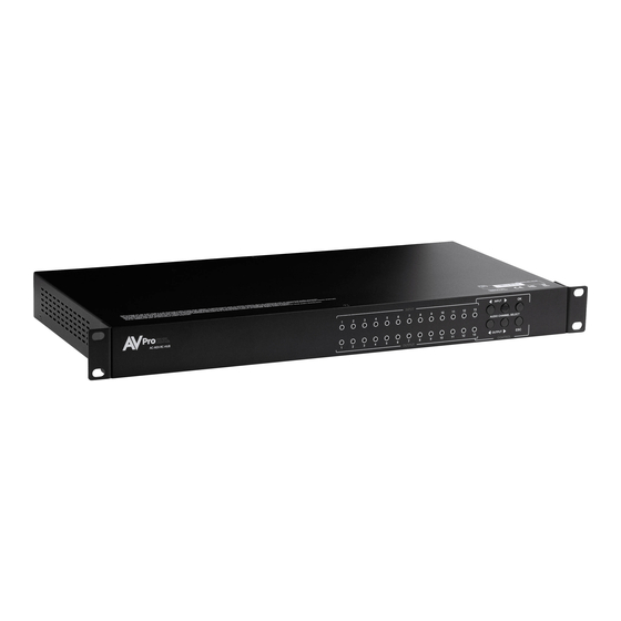
Page 8: Front And Rear Panels
Front and Rear Panels Front Panel Rear Panel INPUT and OUTPUT LEDs • Blue LED status indicator lights for the inputs and outputs AUDIO CHANNEL SELECT • Navigation buttons to cycle through the inputs and outputs CONTROL • Navigation buttons to confirm or exit the selected input and outputs A-LINK FROM EXTENDER TX •... -
Page 9: Installation
INSTALLATION Rack Mounts The AC-AEX-RC-HUB can be mounted in a 1U rack-style enclosure and is compatible with all standard 19- inch rack mounts. The (2x) mounting brackets are pre-assembled to the unit for quick installation. Align the holes on the mounting brackets with the holes on both sides of the rack. -
Page 10: Grounding Cable
Grounding Cable Use a screwdriver to attach the yellow grounding cable to the pre-installed screw on the back of the unit, then attach the other end to a suitable grounded object. FRONT PANEL CONTROL Left and Right Input buttons selects the desired input, indicated by a blue LED under the port number. Left and Right Output buttons selects the desired output, indicated by a blue LED above the port number. -
Page 11: Wiring And Connections
WIRING AND CONNECTIONS Audio Connections AVPro Edge recommends using shielded RCA interconnected cabling between the AC-AEX-RC-HUB and the connected analog devices to maintain a high level of audio performance. The diagram below shows the audio connections of the AC-AEX-RC-HUB. Page 11 of 31... -
Page 12: Rs-232 Control
LAN Wiring The IP control port located in the bottom right corner on the rear panel is used to communicate with the AC-AEX-RC-HUB via a LAN, router, or third-party control system processor. For TCP/IP control, commands use Telnet Port 23. -
Page 13: Initial Setup
Make the physical connections to the input and output devices using the following steps below. For initial setup, it is recommended to connect the AC-AEX-RC-HUB to a LAN (Local Area Network) using a control PC on the same network once all the physical connections are made, followed by accessing the Web UI and checking for any firmware updates to the unit. -
Page 14: Accessing The Web Ui
Accessing the Web UI The AC-AEX-RC-HUB features the built-in AVPro Edge User Interface (AEUI) and can be accessed through a web browser for configuration and control. For initial setup, it is recommended to connect the AC-AEX-RC- HUB to a local area network (LAN) with a computer on the same network to access the built-in Web UI and check for any firmware updates to the unit. - Page 15 If the unit is already installed with the latest version of firmware, a notification window will prompt the message “No update available!” at the top of the page. If a newer version of firmware is detected from the Cloud, a notification window will prompt the message “New firmware update is available!”.
-
Page 16: Navigating The Web Ui
NAVIGATING THE WEB UI The AC-AEX-RC-HUB features the built-in AVPro Edge User Interface (AEUI) and can be accessed through a web browser for configuration and control. Different tools and settings can be selected from the tab pages located on the navigation menu column on the left side of the screen. -
Page 17: Matrix
Matrix The Matrix page layout consists of the Stereo Audio Inputs column on the left and the Outputs grid on the right. Each Input and Output can be individually selected to route the input audio signals to the outputs. Matrix Switching From the Inputs column, select the desired input. -
Page 18: I/O Config
I/O Config The I/O Config tab page features tools and settings for configuring the audio inputs and outputs. Stereo Audio Input Settings Port Shows the audio input port number. Type Shows the audio input connection type. Label Select the text field to enter in a custom name for the input. (Limit of 15 characters) Enabled Select the toggle switch to enable or disable the audio input. -
Page 19: Output Following
Output Following This setting allows an output to mirror, or “follow”, the same operation as another output. It can also be used to create groups of outputs that will continually share the same input source, output volume level, or both. Changes to a followed output will automatically update any outputs when this setting is enabled. -
Page 20: Audio Configuration
Audio Configuration Dropdown menu containing a list of 7 EQ presets. Selecting a preset adjusts the output’s audio to a specific range of frequencies to improve sound quality. Frequency Graphic equalizer showing the individual frequency bands of the output’s audio. NOTE: This graphic equalizer is only intended to be used as a visual reference of the individual audio frequency gains. -
Page 21: System
System IP Settings These can be assigned by a DHCP reservation from the router when the IP Assignment is set to Automatic, or they can be manually entered in when the IP Assignment is set to Manual. Select the Apply button when manually entering in the IP Assignment, IP Address, Subnet Mask, Gateway, Primary DNS, and Secondary DNS for changes to take effect. -
Page 22: Ip Control
IP Control Enable Select the toggle switch to enable or disable IP/TCP control. Port Select the text field to set the Telnet port. Default is Telnet port 23. Admin Web Interface Select the Secure toggle switch to enable (green) or disable (red). When enabled, the username and password can be changed. -
Page 23: User Web Interface
User Web Interface Select the Secure toggle switch to enable (green) or disable (grey). When enabled, the username and password can be changed. NOTE: The Admin Web Interface must first be enabled before this setting can be changed. With the Admin and User Web Interfaces enabled, no menus will be accessible on the Web UI without first logging in. -
Page 24: Cloud Services
Cloud Services Cloud Services allows OTA (Over-the-Air) firmware updates to be performed onto the unit. This allows the unit to search the Cloud for the latest versions of firmware, as well as enable third-party remote management services. If Cloud Services are disabled, the unit will opt out of any previously enabled services and will not be able to access OTA firmware updates. -
Page 25: Hardware
From this screen, newer versions of firmware can be viewed before they are installed. Select the Upgrade button. The unit will now begin installing the latest versions of firmware. DO NOT refresh the webpage or power off the unit during the update. Once the progress bar reaches 100%, select the Close button and refresh the webpage. -
Page 26: Console
Console The Web UI features a built-in command console that allows API commands to be sent directly to the unit. Command List Command Action Help Show global system status SET RST Reset to factory defaults SET RBT System reset to reboot SET LAN RBT Set LAN MCU reset to reboot SET ADDR xx... - Page 27 GET OUTx MUTE Get Audio Output Mute/Unmute {x=[0~12](0=all)} GET OUTx VOL Get Output x EQ-Audio Volume Level {x=[0~12](0=all)} GET OUTx EQ Get Output x Audio Volume EQ Mode Status {x=[0~12](0=all)} GET OUTx BAL Get Output x Balance {x=[0~12](0=all), y=[0~20, Left=0, Right=20, Balanced=10]} Network Setup Commands SET RIP xxx.xxx.xxx.xxx Set Route IP Address to xxx.xxx.xxx.xxx (xxx=[000~255])
-
Page 28: Troubleshooting
Static, Buzzing, or Humming Noises – Use shielded RCA cabling between the AC-AEX-RC-HUB and the • connected analog devices to maintain a high level of audio performance. Ground the matrix to the conducting parts (equipment rack, mounting devices, truss systems, electrical switchboards, metal electrical conduits, etc.). -
Page 29: Support
Objects or liquids have gotten into the unit • The unit has been exposed to rain • The unit does not operate normally or exhibits a marked change in performance • The unit has been dropped or the housing damaged •... -
Page 30: Obtaining An Rma
Obtaining an RMA Dealers, Re-sellers, and Installers can request an RMA from AVPro Edge Tech Support Rep or their Sales Engineer. Or you may email support@avproedge.com or fill out the general contact form at www.avproedge.com/contact End users may not request and RMA directly from AVPro Edge and will be referred back to the Dealer, Re- seller, or Installer. -
Page 31: Exclusive Remedy
original product manufacturer capabilities. Because of performance, price and functionality issues, product redevelopment is not an option.” Discontinued or out of production items will be credited at fair market value towards a current product of equal or comparable capabilities and cost. Fair market value is determined by AVPro Edge. Exclusive Remedy To the maximum extent permitted by law, this limited warranty and the remedies set forth above are exclusive and in lieu of all other warranties, remedies, and conditions, whether oral or written, express or...
Need help?
Do you have a question about the AC-AEX-RC-HUB and is the answer not in the manual?
Questions and answers