
Related Manuals for AVProEdge conferX AC-CX84-AUHD


Summary of Contents for AVProEdge conferX AC-CX84-AUHD
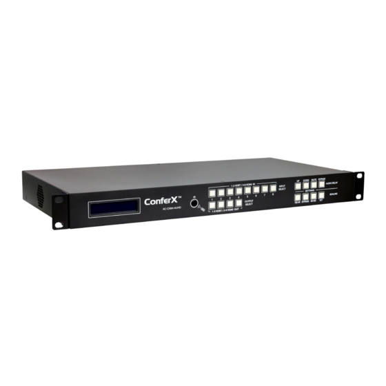
- Page 1 User Manual 8x4 HDMI/HDBaseT Classroom/Conference Room Matrix switcher Featuring Quick Switch AC-CX84-AUHD...
-
Page 2: Table Of Contents
I N T R O D U C T I O N � � � � � � � � � � � � � � � � � � � � � � � � � � � � � � � � � � � � � � � � � � � � � � � � � � � � � � � � � � � � � � � � � � � � � � � � � � � � � � � � � � � � � � � � � � � � � 4 F E AT U R E S �... - Page 3 W E B I N T E R FA C E : AU D I O M AT R I X � � � � � � � � � � � � � � � � � � � � � � � � � � � � � � � � � � � � � � � � � � � � � � � � � � � � � � � � � � � � � � � � � 2 9 W E B I N T E R FA C E : E D I D M A N A G E �...
-
Page 4: Introduction
Introduction The ConferX 8x4 Matrix Switcher is the ideal solution for any conference room, classroom or hud- dle space. This 4K switcher can display any of the eight sources through both the HDBaseT and HDMI output ports. All four of the outputs are completely independent of each other allowing the user to show four sources at the same time. -
Page 6: Front & Rear Panel Overview
Front & Rear Panel Overview Basic Installation The unit has an Auto-Config on boot up and reception of new sources and displays to maximize plug and play installation: 1. Plug in the display(s) or sink devices 2. Plug in the sources 3. -
Page 7: Front Panel Control: Buttons
Front Panel Control: Buttons... -
Page 8: Front Panel: Switching Control
Front Panel: Switching Control The AC-CX84-AUHD can be switched from the front panel by pressing the desired OUTPUT button first, then the desired INPUT button: 1. Press the desired OUTPUT button (1 & 3 are HDBT, 2 & 4 are HDMI). 2. -
Page 9: Front Panel: Edid Setup
Front Panel: EDID Setup This matrix has 29 factory defined EDID settings. It also has 3 user defined EDID memories. The user EDID memories are independent to each input and can be set differently. The user defined EDID can be uploaded using the free PC Control software or RS-232. In addition, you can choose to read the EDID from the desired output and the captured EDID will automatically store and overwrite the EDID in “USER EDID 1”... -
Page 10: F R O N T Pa N E L C O N T R O L - S C A L I N
Front Panel Control - Scaling The AC-CX84-AUHD has scalers built into every output. The HDbaseT Ports can be DOWNSCALED and the HDMI Ports can be UPSCALED. The scalers are set on the OUTPUT side of the switch and each can have separate settings. ·... -
Page 11: Au D I O C O N T R O L : Au D I O B I N D I N
Audio Control: Audio Binding The AC-CX84-AUHD has 3 settings for the Extracted Audio. • BIND TO OUTPUT (extracted audio switches with the video, this is the default mode) • BIND TO INPUT (extracted audio is fixed to the corresponding input by the same number) •... -
Page 12: Au D I O I N P U T : L I N E I N / M I C R O P H O N
Audio Input: Line In/Microphone The audio input port can be enabled and disabled by using the following command. SET OUTx EXA MIC EN/DIS : Set Ex-Audio Microphone Output Enable/Disable{x=[0~4](0=ALL)} Example #1 - SET OUT1 EXA MIC EN In the example below, the audio from the microphone will be output on extracted audio #1 (green). Extracted audio ports 2-4 have audio routed from the source (blue). -
Page 13: F R O N T Pa N E L : D I S P L Ay I P I N F O R M At I O
Front Panel: Display IP Information The Extracted Audio ports can be independently controlled while in MATRIX Mode. In order to see the current IP settings, press and hold (for 3 secondsv) INPUT 3 and INPUT 4 buttons simultaneously. This screen will change every 3 seconds showing additional settings (host, net mask, router IP). -
Page 14: R S 2 3 2 C O N F I G U R At I O
RS232 Configuration: The AC-CX84-AUHD has two distinct RS232 Ports. 1. HDBT - This is for transmitting RS232 signals from the Matrix to the remote HDBaseT Receiver 2. MATRIX - This is for sending signals to the AC-CX84- AUHD Matrix for controlling the device. An example is shown on the next page. -
Page 15: R S 2 3 2 A N D T C P / I P C O M M A N D
RS232 and TCP/IP Commands: The Matrix can be controlled with either RS-232 or TCP/IP commands. Certain switching or format configurations can only be done using these commands. We recommend using either the MyUART (RS-232 - free) or Hercules (TCP/IP - free) apps as they are very easy to use for sending commands to the machine. -
Page 16: D E V I C E A D D R E S S E S W H E N U S I N G S E R I A L C O M M U N I C At I O
Device Addresses When Using Serial Communication: NOTE: Only set device address when cascading multiple units together and using RS232 as your control method! You also have to send the device address when doing advanced routing while sending commands by serial (next page) even if it is default “A00”. -
Page 17: H O W T O R O U T E R S 2 3 2 C O M M A N D S W H E N U S I N G S E R I A
How to route RS232 Commands when using serial: The routing command is very straight forward but you have to take care to make sure you format it correctly. The main thing to consider before you begin: 1. You are actually sending 2 commands (route & device command) so depending on what you are using to send the command the format varies slightly - We show some examples below. - Page 18 In the following example we are using a program called MYUART Assist. We make this program free- ly available form www.avproedge.com. You will notice in the example that it is on 2 lines. This is because you have to separate the com- mands with a return.
- Page 19 Using TELNET (IP): On Controls Examples Green = Route Command Red = Command to be sent to device This first example is when sending an ASCII Command \x0DA01SET RS PTH OUT1 LEN17 BR4\x0D\x0A\x0DSET OUT4 VS IN5\x0A\x0D\x0D You can also convert to pure HEX and send a command this way: \x0A\x41\x30\x31\x53\x45\x54\x20\x52\x53\x20\x50\x54\x48\x20\x4F\x55\x54\x31\x20\x4C\x45\ x4E\x31\x37\x20\x42\x52\x34\x0D\x0A\x53\x45\x54\x20\x4F\x55\x54\x32\x20\x56\x53\x20\x49\ x4E\x32\x0D\x0A...
-
Page 22: I R C O N F I G U R At I O
IR Configuration IR Mode Slide Switch: (On Back) This is used to select a preferred IR Mode - There are two modes: • IR-EYE - The IR Input will be configured to operate with an IR Receiver Eye. • IR PASS - The IR Input will be configured to safely operate with a direct connection from a control system using a mono or stereo 3.5mm cable. -
Page 23: I R C O N F I G U R At I O N C O N T I N U E
IR Configuration Continued The IR OUT port is send IR signals out of an IR Emitter (Pictured below) that originate at the HDBas- eT Receiver OR HDBaseT Transmitter IR Sensor IR Emitter... -
Page 24: Au D I O O U T P U T L O G I C A N D C A B L E P R E
Audio Output Logic and Cable Prep: You can extract audio from toslink or balance 2CH Audio. Audio outputs are an un-decoded output. This means that what goes in, is what goes out. 2CH Balanced Audio Port - Supports 2CH PCM audio only, which is ideal for 2 Channel systems and zoned audio systems. -
Page 25: M I C R O P H O N E I N A N D C A B L E P R E
Microphone IN and Cable Prep: The Microphone/Line InputThere are 3 settings for the Microphone Input, they are 1. LINE IN - 1. LINE IN - Balance Mono Anolog Audio Input (use + and Ground VPP should be less than 2 Volts 2. -
Page 26: W E B I N T E R Fa C E : S W I T C H I N
Web Interface: Switching Use this page to switch between inputs and outputs from the web interface. -
Page 27: W E B I N T E R Fa C E : V I D E O S E T T I N
Web Interface: Video Setting Video Scaler Modes: The AC-CX84-AUHD has video scaling features built-in. The HDBT outputs can downscale a 4k signal to a HD signal (1080P). And the HDMI outputs can upscale HD signals (1080p) to 4k. Default set- tings shown above. -
Page 28: W E B I N T E R Fa C E : Au D I O S E T T I N
Web Interface: Audio Setting EX-Audio Delay: This setting allows the user to change the audio delay to overcome lip-sync issues when using audio separate from HDMI. The user can choose from the above options in milliseconds. Bp = Bypass or No Delay (default). -
Page 29: W E B I N T E R Fa C E : Au D I O M At R I
Web Interface: Audio Matrix Audio Matrix: This allows the user to route the audio in a matrix fashion for the extracted audio ports. *NOTE: The Audio Matrix Function only works if “MATRIX” is selected on the right (See next explanation). Audio Status: This allows the user to turn ON and OFF the extracted audio output. -
Page 30: W E B I N T E R Fa C E : E D I D M A N A G
Web Interface: EDID Manage Using the built-in EDID manager, a multitude of EDID’s can be set for each input, and each input can be assigned a different EDID. This should be used to optimize sources or to manage infrastructure. The EDID options are: 1080P_2CH 1080P_8CH_HDR 1080P_6CH... -
Page 31: W E B I N T E R Fa C E : S Y S T E M S E T T I N G
Web Interface: System Settings IP Settings: Port Alias Settings: Set network settings such as: Rename inputs and outputs for easy management. Each custom name is limited to eight (8) characters. · Static IP · Subnet Mask · Router IP · TCP Port ·... -
Page 32: T R O U B L E S H O O T I N
8. Verify Source is set to output 8ch if using TOSLINK 9. Note: This unit does NOT Down-Mix, for 2Ch port to function source must be set to 2Ch. 10. Still having issues, contact us Support Direct - +1-605-977-3477 All inquiries - 1-605-274-6055 Submit a support request ticket https://support.avproedge.com/hc/en-us/requests/new... -
Page 33: M A I N T E N A N C
Maintenance To ensure reliable operation of this product as well as protecting the safety of any person using or handling this device while powered, please observe the following instructions. · Use the power supplies provided. If an alternate supply is required, check voltage, polarity and that it has sufficient power to supply the device it is connected to. -
Page 34: S U P P O R
If your product does not work properly because of a defect in materials or workmanship, AVProEdge (referred to as “the warrantor”) will, for the length of the period indi- cated as below, (Parts/Labor (10) Years), which starts with the date of original purchase (“Limited Warranty period”), at its option either (a) repair your product with new or refurbished parts, or (b) - Page 37 Thank you for choosing AVProEdge! Please contact us with any questions, we are happily at your service! AVProEdge 2222 E 52nd St N ~ Sioux Falls, SD 57104 1-877-886-5112 ~ 605-274-6055 support@avproedge.com...
Need help?
Do you have a question about the conferX AC-CX84-AUHD and is the answer not in the manual?
Questions and answers