Table of Contents
Advertisement
Available languages
Available languages
Quick Links
Advertisement
Table of Contents

Related Manuals for Cameo STUDIO PAR 4 G2


Summary of Contents for Cameo STUDIO PAR 4 G2
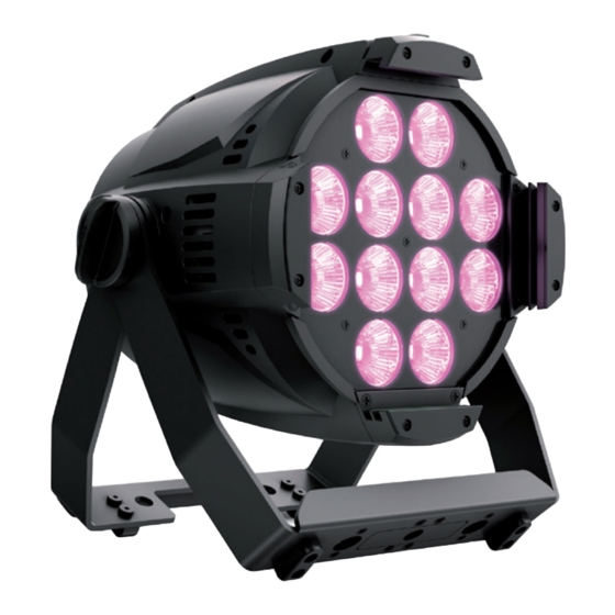
- Page 1 BEDIENUNGSANLEITUNG MANUEL D`UTILISATION MANUAL DE USUARIO INSTRUKCJA OBSŁUGI MANUALE D‘ USO RGBW STUDIO PAR 4 G2 LED PAR SPOTLIGHT WITH 12 X RGBW 4-IN-1 LED CLPST4G2 STUDIO PAR 6 G2 LED PAR SPOTLIGHT WITH 12 X RGBAWUV 6-IN-1 LED CLPST6G2...
-
Page 2: Table Of Contents
CONTENTS / INHALTSVERZEICHNIS / CONTENU / CONTENIDO / TREŚĆ / CONTENUTO ENGLISH INFORMATION ON THIS USER MANUAL INTENDED USE DEFINITIONS AND SYMBOL EXPLANATIONS SAFETY INSTRUCTIONS NOTES FOR MOBILE INDOOR DEVICES INCLUDED INTRODUCTION CONNECTIONS, OPERATING AND DISPLAY ELEMENTS OPERATION SETUP AND INSTALLATION MOUNTING THE FILTER FRAME CARE, MAINTENANCE AND REPAIR TECHNICAL DATA... - Page 3 CONTENTS / INHALTSVERZEICHNIS / CONTENU / CONTENIDO / TREŚĆ / CONTENUTO DEUTSCH INFORMATIONEN ZU DIESER BEDIENUNGSANLEITUNG BESTIMMUNGSGEMÄSSER GEBRAUCH BEGRIFFS- UND SYMBOLERKLÄRUNGEN SICHERHEITSHINWEISE HINWEISE FÜR ORTSVERÄNDERLICHE INDOOR-GERÄTE LIEFERUMFANG EINFÜHRUNG ANSCHLÜSSE, BEDIEN- UND ANZEIGEELEMENTE BEDIENUNG AUFSTELLUNG UND MONTAGE FILTERRAHMEN MONTIEREN PFLEGE, WARTUNG UND REPARATUR TECHNISCHE DATEN MINDESTABSTAND ZUR BELEUCHTETEN FLÄCHE MINDESTABSTAND ZU NORMAL ENTFLAMMBAREN MATERIALIEN...
- Page 4 ESPAÑOL INFORMACIÓN SOBRE ESTE MANUAL DE INSTRUCCIONES USO PREVISTO TÉRMINOS Y SÍMBOLOS INSTRUCCIONES DE SEGURIDAD INDICACIONES PARA EQUIPOS PORTÁTILES DE INTERIOR VOLUMEN DE SUMINISTRO INTRODUCCIÓN CONEXIONES, ELEMENTOS DE MANEJO Y ELEMENTOS DE VISUALIZACIÓN MANEJO INSTALACIÓN Y MONTAJE MONTAJE DEL PORTAFILTROS CUIDADO, MANTENIMIENTO Y REPARACIÓN DATOS TÉCNICOS DISTANCIA MÍNIMA CON RESPECTO A LA SUPERFICIE ILUMINADA...
- Page 5 ITALIANO INFORMAZIONI SUL PRESENTE MANUALE D'USO UTILIZZO CONFORME SPIEGAZIONE DI CONCETTI E SIMBOLI INDICAZIONI SULLA SICUREZZA AVVERTENZE PER DISPOSITIVI INDUSTRIALI PORTATILI FORNITURA INTRODUZIONE CONNETTORI, ELEMENTI DI COMANDO E VISUALIZZAZIONE UTILIZZO INSTALLAZIONE E MONTAGGIO INSTALLAZIONE DEL PORTAFILTRO PULIZIA, MANUTENZIONE E RIPARAZIONE DATI TECNICI DISTANZA MINIMA DALLA SUPERFICIE ILLUMINATA DISTANZA MINIMA DAI MATERIALI NORMALMENTE INFIAMMABILI...
-
Page 6: Information On This User Manual
This device has been developed and manufactured to the highest quality standards to ensure many years of problem-free operation. Please read this user manual carefully to be able to use your new Cameo product quickly and optimally. Further information about Cameo Light is avail- able on our website CAMEOLIGHT.COM. -
Page 7: Safety Instructions
This symbol identifies hazards that can cause electric shock. This symbol identifies hazardous areas or hazardous situations. This symbol indicates hazards caused by hot surfaces. This symbol indicates hazards caused by intense light sources. This symbol indicates a device in which there are no user-replaceable parts. This symbol indicates additional information on the operation of the product. - Page 8 ATTENTION: 1. Do not switch on the device if it has been exposed to extreme temperature fluctu- ations (for example, following transport). Moisture and condensation can damage the device. Switch on the device only when it has reached room temperature. 2.
- Page 9 CAUTION: 1. Moving components such as mounting brackets may become jammed. 2. In the case of devices with motor-driven components, there is a risk of injury due to the movement of the device. Sudden movement of the device can cause shock reactions.
-
Page 10: Notes For Mobile Indoor Devices
Please check the completeness and integrity of the delivery and notify your distribution partner immediately after purchase if the delivery is not complete or if it is damaged. Included with the CLPST4G2: X 1x STUDIO PAR 4 G2 spotlight X 1x filter frame (pre-assembled) X 1x power cable... -
Page 11: Introduction
INTRODUCTION 12 X 8W RGBW STUDIO PAR G2 SPOTLIGHT CLPST4G2 12 X 12 W RGBWA+UV STUDIO PAR G2 SPOTLIGHT CLPST6G2 CONTROL FUNCTIONS: CLPST4G2: 1-channel DIM UC, D3-channel macro, 4-channel RGBW, 4-channel strobe macro, D8-channel strobe macro, 10-channel macro control, D6-channel direct 8 bit, 10-channel direct 16 bit and 14-channel full access DMX control CLPST6G2: 1-channel DIM UC, D3-channel macro, 4-channel strobe macro, 6-channel RGBWAUV, D10-channel strobe macro, 12-channel macro control, D9-channel direct 8 bit, 14-channel direct... -
Page 12: Connections, Operating And Display Elements
CONNECTIONS, OPERATING AND DISPLAY ELEMENTS The STUDIO PAR 4 G2 and STUDIO PAR 6 G2 models feature identical connections, operating and display elements. POWER IN Blue Power Twist mains input socket. Operating voltage 100–240 V AC/50–60 Hz. A suitable power cable with Power Twist plug is included. - Page 13 FUSE for 5 x 20 mm fuses. IMPORTANT: Replace the fuse only with a fuse of the same type and value. In the event of repeated fuse failure, please contact an authorised service centre. DMX IN Male 3-pin XLR socket for connection to a DMX control device (e.g. DMX console). DMX OUT Female 3-pin XLR socket for sending the DMX control signal.
-
Page 14: Operation
• As soon as the spotlight is correctly connected to the power supply, the following are displayed in succession: "Software Update Please Wait" (for service purposes only), "Welcome to Cameo," the model name and the software version. After this process, the spotlight is operational and the previously activated operating mode is launched. - Page 15 CONFIGURING DMX START ADDRESS (DMX Address) Starting from the main display, press MENU to enter the main menu. Now use to select the menu item DMX address and confirm with ENTER. Now use the buttons to configure the desired DMX start address and press ENTER to confirm (highest value dependent upon activated DMX mode).
- Page 16 DMX DELAY The DMX Delay function is a simple way to create a running light effect with a large number of spotlights that are all the same model and that are all running the same software version. This is otherwise only achievable with a suitable DMX controller and time-consuming programming. All the spotlights used (same models, same software version) are set to the same DMX operating mode with DMX delay channel and controlled via the same DMX start address.
- Page 17 AUTO STANDALONE MODE The 6 available auto programs partly comprise non-editable colour change sequences and partly random scenes. Brightness and running speed can be set separately for each program. Starting from the main display, press MENU to enter the main menu. Using and , select the menu item Stand Alone, confirm with ENTER, then select Static, confirm with ENTER, then select the desired program and confirm once again with ENTER.
- Page 18 COLOUR PRESET STANDALONE MODE 15 different colour presets plus 4 individually adjustable user presets are available. The brightness and a strobe effect can be set at a higher level. Starting from the main display, press MENU to enter the main menu. Using and , select the menu item Stand Alone and confirm with ENTER, then select Colour Preset and confirm once again with ENTER.
- Page 19 EDITING USER PRESETS (Edit User Colour) The four user presets available in the standalone mode Colour Preset can be edited individually. Starting from the main display, press MENU to enter the main menu. Using and , select the menu item Stand Alone, confirm with ENTER, then select Static and confirm once again. Now to select the desired preset and confirm with ENTER.
- Page 20 Step 3 15 colours from Colour Preset Red-Cold White 4 colours from User Colour User Color 1 – User Color 4 Blackout Black Skip step Skip Step Step 4 “ “ Step 5 “ “ Step 6 “ “ Step 7 “...
- Page 21 Assign the spotlights to one of up to 24 groups (plus Group 0) according to preference, whereby several spotlights can be assigned to one group. The group number is also the factor by which the delay time set in the master unit is multiplied. Setup example: Delay Group 0 Delay Group 1...
- Page 22 Dimmer = Dimmer curve Linear Light intensity increases linearly with DMX Curve value Exp (Expo- Light intensity can be finely adjusted at nential) lower DMX values and broadly adjusted at higher DMX values Logarith- Light intensity can be broadly adjusted at lower DMX values and finely adjusted at higher DMX values S-curve...
- Page 23 SYSTEM INFORMATION (System Info) Starting from the main display, press MODE to enter the main menu. Now use and to select the menu item System Info and confirm with ENTER. Menu DMX Address DMX Mode DMX Delay Stand Alone Slave Settings System Info This will take you to the submenu for accessing the system information (see table, selection with...
-
Page 24: Setup And Installation
SETUP AND INSTALLATION HAZARD: Overhead mounting requires extensive experience, including the calculation of the load limit values of the installation material and regular safety inspection of all installation materials and spotlights. If you do not have these qualifications, do not attempt to perform an installation yourself. -
Page 25: Mounting The Filter Frame
MOUNTING THE FILTER FRAME To mount the filter frame (or the optionally available barndoor), first move the spring-loaded fuse holder on the top of the spotlight to the right to unlock it, and then flip it up (Figure A). Insert the filter frame (or the optionally available barndoor) into the grooves of the lateral and bottom holders from above. -
Page 26: Care, Maintenance And Repair
CARE, MAINTENANCE AND REPAIR In order to ensure the long-term, proper functioning of the device, it must be regularly cleaned and, if necessary, maintained. The maintenance requirement depends on the intensity of use and the environment in which it is used. We generally recommend a visual inspection before each operation. -
Page 27: Technical Data
TECHNICAL DATA Item number CLPST4G2 CLPST6G2 Product category Static LED light Static LED light Type Studio PAR Studio PAR Light source 12 x 4in1 RGBW 8W SMD LED 12 x 6in1 RGBAWuV 12W SMD LED Luminous flux 4620lm @ Full On 4675lm @ Full On Lense / optic 12 x Acryl Lense... -
Page 28: Minimum Distance To Illuminated Surface
Operation 100V AC – 240V AC; 50Hz-60Hz 100V AC – 240V AC; 50Hz-60Hz voltage Max. current 0.38A @230V; 0.67A @110V 0.54A @230V; 1.09A @110V Inrush current 13.3A 13.3A Max. power 87W @230V; W 74@110V 124W @230V; W 120@110V consumption Fuse Cos Phi 0.990 0.998... -
Page 29: Disposal
DISPOSAL Packaging: 1. Packaging can be fed into the reusable material cycle using the usual disposal methods. 2. Please separate the packaging in accordance with the disposal laws and recy- cling regulations in your country. Device: 1. This device is subject to the European Directive on Waste Electrical and Electronic Equipment, as amended. - Page 30 FCC STATEMENT This equipment has been tested and found to comply with the limits for a Class B digital device, pursuant to part 15 of the FCC Rules. These limits are designed to provide reasonable protection against harmful interference in a residential installation. This equipment generates, uses and can radiate radio frequency energy and, if not installed and used in accordance with the instructions, may cause harmful interference to radio communications.
-
Page 31: Informationen Zu Dieser Bedienungsanleitung
Dieses Gerät wurde unter hohen Qualitätsanforderungen entwickelt und gefertigt, um viele Jahre einen reibungslosen Betrieb zu gewährleisten. Bitte lesen Sie diese Bedienungsanleitung sorgfäl- tig, damit Sie Ihr neues Produkt von Cameo Light schnell und optimal einsetzen können. Weitere Informationen über Cameo Light erhalten Sie auf unserer Website CAMEOLIGHT.COM. -
Page 32: Sicherheitshinweise
Dieses Symbol kennzeichnet Gefahren, die einen elektrischen Schlag verursachen können. Dieses Symbol kennzeichnet Gefahrenstellen oder gefährliche Situationen. Dieses Symbol kennzeichnet Gefahren durch heiße Oberflächen. Dieses Symbol kennzeichnet Gefahren durch intensive Lichtquellen. Dieses Symbol kennzeichnet ein Gerät, in dem sich keine vom Benutzer austauschbaren Teile befinden. - Page 33 ACHTUNG: 1. Nehmen Sie das Gerät nicht in Betrieb, wenn es starken Temperaturschwankungen ausgesetzt war (beispielsweise nach dem Transport). Feuchtigkeit und Kondensat könnten das Gerät beschädigen. Schalten Sie das Gerät erst ein, wenn es Umge- bungstemperatur erreicht hat. 2. Stellen Sie sicher, dass die Spannung und die Frequenz des Stromnetzes mit den auf dem Gerät angegebenen Werten übereinstimmen.
- Page 34 VORSICHT: 1. Bei beweglichen Bauteilen wie Montagebügeln, oder sonstigen beweglichen Bau teilen besteht die Möglichkeit sich zu klemmen. 2. Bei Geräten mit motorisch angetriebenen Bauteilen besteht Verletzungsgefahr durch die Bewegung des Gerätes. Plötzliche Gerätebewegungen können zu Schreck reaktionen führen. 3. Die Gehäuseoberfläche des Geräts kann sich im regulären Betrieb stark erwärmen. Stellen Sie sicher, dass ein versehentliches Berühren des Gehäuses ausgeschlos- sen ist.
-
Page 35: Hinweise Für Ortsveränderliche Indoor-Geräte
Bitte überprüfen Sie die Vollständigkeit und Unversehrtheit der Lieferung und benachrichtigen Sie Ihren Vertriebspartner bitte unverzüglich nach dem Kauf, falls die Lieferung nicht komplett oder beschädigt ist. Im Lieferumfang des Produkts CLPST4G2 sind enthalten: X 1x STUDIO PAR 4 G2 Scheinwerfer X 1x Filterrahmen (vormontiert) X 1x Netzkabel X Bedienungsanleitung... -
Page 36: Einführung
EINFÜHRUNG 12 X 8W RGBW STUDIO PAR G2 SCHEINWERFER CLPST4G2 12 X 12W RGBWA+UV STUDIO PAR G2 SCHEINWERFER CLPST6G2 STEUERUNGSFUNKTIONEN: CLPST4G2: 1-Kanal DIM UC, D3-Kanal Macro , 4-Kanal RGBW, 4-Kanal Strobe Macro , D8-Kanal Strobe Macro, 10-Kanal Macro Control, D6-Kanal Direct 8 Bit, 10-Kanal Direct 16 Bit und 14-Kanal Full Access DMX-Steuerung CLPST6G2: 1-Kanal DIM UC, D3-Kanal Macro, 4-Kanal Strobe Macro, 6-Kanal RGBWAUV, D10-Kanal Strobe Macro, 12-Kanal Macro Control, D9-Kanal Direct 8 Bit, 14-Kanal Direct 16 Bit,... -
Page 37: Anschlüsse, Bedien- Und Anzeigeelemente
ANSCHLÜSSE, BEDIEN- UND ANZEIGEELEMENTE Die Modelle STUDIO PAR 4 G2 und STUDIO PAR 6 G2 verfügen über identische Anschlüsse, Bedien- und Anzeigeelemente POWER IN Blaue Power Twist Netzeingangsbuchse. Betriebsspannung 100 – 240V AC / 50 – 60Hz. Ein geeignetes Netzkabel mit Power Twist Gerätestecker befindet sich im Lieferumfang. - Page 38 FUSE Sicherungshalter für 5 x 20mm Sicherungen. WICHTIGER HINWEIS: Ersetzen Sie die Sicherung ausschließlich durch eine Sicherung des gleichen Typs und mit gleichen Werten. Sollte die Sicherung wiederholt auslösen, wenden Sie sich bitte an ein autorisiertes Servicezentrum. DMX IN Männliche 3-Pol XLR-Buchse zum Anschließen eines DMX-Kontrollgeräts (z.B. DMX-Pult). DMX OUT Weibliche 3-Pol XLR-Buchse zum Weiterleiten des DMX-Steuersignals.
-
Page 39: Bedienung
• Sobald der Scheinwerfer korrekt am Stromnetz angeschlossen ist, wird während des Start- vorgangs nacheinander“Software Update Please Wait“ (nur für Servicezwecke), „Welcome to Cameo“, die Modellbezeichnung und die Softwareversion im Display angezeigt. Nach diesem Vorgang ist der Scheinwerfer betriebsbereit und die Betriebsart, die zuvor aktiviert war, wird gestartet. - Page 40 DMX-STARTADRESSE EINSTELLEN (DMX Address) Ausgehend von der Hauptanzeige gelangen Sie durch Drücken auf MENU in das Hauptmenü. Mit Hilfe der Taster bzw. wählen Sie nun den Menüpunkt DMX Address aus und bestätigen mit ENTER. Stellen Sie nun die DMX-Startadresse wunschgemäß mit Hilfe von bzw.
- Page 41 DMX-DELAY Mit Hilfe der Funktion DMX-Delay kann auf einfache Weise mit einer beliebig großen Anzahl Scheinwerfern des gleichen Modells und Softwarestands ein Lauflichteffekt realisiert werden, der sonst nur mit einem geeigneten DMX-Controller und aufwändiger Programmierung erreicht wer- den könnte. Dabei werden alle einbezogenen Scheinwerfer (gleiche Modelle, gleicher Software- stand) auf die gleiche DMX-Betriebsart mit DMX-Delay-Kanal eingestellt und auf der gleichen DMX-Startadresse angesteuert.
- Page 42 STAND-ALONE-BETRIEBSART AUTO Die 6 verfügbaren Auto-Programme bestehen teils aus fest programmierten Farbwechsel- sequenzen und teils sie sind Zufallsszenen. Helligkeit, Laufgeschwindigkeit sind für jedes Programm separat einstellbar. Ausgehend von der Hauptanzeige gelangen Sie durch Drücken auf MENU in das Hauptmenü. wählen Sie nun den Menüpunkt Stand Alone aus, bestätigen mit ENTER, Mit Hilfe von bzw.
- Page 43 STAND-ALONE-BETRIEBSART COLOR PRESET 15 verschiedene Farb-Presets plus 4 individuell einstellbare User-Presets stehen zur Verfügung. Die Helligkeit und ein Stroboskop-Effekt können übergeordnet eingestellt werden. Ausgehend von der Hauptanzeige gelangen Sie durch Drücken auf MENU in das Hauptmenü. Mit Hilfe von wählen Sie nun den Menüpunkt Stand Alone aus, bestätigen mit ENTER, wählen dann Color Preset aus und bestätigen abermals mit ENTER.
- Page 44 USER-PRESETS EDITIEREN (Edit User Color) Die vier in der Stand-Alone-Betriebsart Color Preset verfügbaren User-Presets sind individuell editierbar. Ausgehend von der Hauptanzeige gelangen Sie durch Drücken auf MENU in das Haupt- menü. Mit Hilfe von wählen Sie nun den Menüpunkt Stand Alone aus, bestätigen mit ENTER, wählen dann Edit User Color aus und bestätigen abermals.
- Page 45 Step 3 15 Farben aus Color Preset Red – Cold White 4 Farben aus User Color User Color 1 – User Color 4 Blackout Black Schritt überspringen Skip Step Step 4 " " Step 5 " " Step 6 " "...
- Page 46 Ordnen Sie die Scheinwerfer nach Wunsch einer von bis zu 24 Gruppen (plus Gruppe 0) zu, wobei auch mehrere Scheinwerfer einer Gruppe zugeordnet werden können. Die Gruppennummer ist gleichzeitig der Faktor, mit dem die in der Master-Einheit eingestellte Delay-Zeit multipliziert wird. Setup-Beispiel: Delay Group 0 Delay Group 1...
- Page 47 = LED PWM Frequenz 650Hz, Auswählen der LED PWM Frequenz 1530Hz, 3600Hz, 12000Hz, 18900Hz, 25000Hz Dimmer = Dimmerkurve Linear Die Lichtintensität steigt linear mit dem Curve DMX-Wert an Exp (Expo- Die Lichtintensität lässt sich im unteren nential) DMX-Wertbereich fein und im oberen DMX-Wertbereich grob einstellen Logarith- Die Lichtintensität lässt sich im unteren...
- Page 48 Load = Zurücksetzen der Factory Zurücksetzen auf Werkseinstellungen: Default Einstellungen Reset durchführen mit ENTER, abbrechen mit MENU Preset A Zurücksetzen auf Preset A: Reset durch- führen mit ENTER, abbrechen mit MENU Preset B Zurücksetzen auf Preset B: Reset durch- führen mit ENTER, abbrechen mit MENU Preset C Zurücksetzen auf Preset C: Reset durch- führen mit ENTER, abbrechen mit MENU...
-
Page 49: Aufstellung Und Montage
AUFSTELLUNG UND MONTAGE GEFAHR: Überkopfmontage erfordert umfassende Erfahrung, einschließlich der Berechnung der Grenzwerte für die Arbeitslast, des verwendeten Installationsmaterials und der regelmäßigen Sicherheitsüberprüfung aller Installationsmaterialien und Schein- werfer. Wenn Sie diese Qualifikationen nicht haben, versuchen Sie nicht, eine Installation selbst durchzuführen, sondern nutzen Sie die Hilfe von professionellen Unternehmen. Es besteht die Gefahr, dass sich nicht korrekt montierte und gesicherte Geräte lösen und herabfallen. -
Page 50: Filterrahmen Montieren
Der optional erhältliche, werkzeuglos ausklappbare 16 mm TV-Zapfen CLZSPIN16 kann an Stelle der Montageplatte mit Montageloch am U-Bügel montiert werden (F). FILTERRAHMEN MONTIEREN Zum Montieren des Filterrahmens (bzw. des optional erhältlichen Flügelbegrenzers) schieben Sie zunächst die gefederte Sicherungshalterung auf der Oberseite des Scheinwerfers zum Entrie- geln nach rechts und klappen sie dann nach oben (Abbildung A). -
Page 51: Pflege, Wartung Und Reparatur
PFLEGE, WARTUNG UND REPARATUR Um die einwandfreie Funktion des Geräts auf Dauer zu gewährleisten, muss es regelmäßig ge- pflegt und bei Bedarf gewartet werden. Der Pflege- bzw. Wartungsbedarf steht in Abhängigkeit der Nutzungsintensität und -umgebung. Wir empfehlen generell eine Sichtprüfung vor jeder Inbetriebnahme. Weiterhin empfehlen wir alle 500 Betriebsstunden, oder bei geringerer Nutzungsintensität spätestens nach Ablauf eines Jahres alle unten genannten und zutreffenden Pflegemaßnahmen durchzuführen. -
Page 52: Technische Daten
TECHNISCHE DATEN Artikelbezeichnung CLPST4G2 CLPST6G2 Produktkategorie Statische LED-Lampe Statische LED-Lampe Studio-PAR Studio-PAR Scheinwerfer 12 x 4-in-1-SMD-LED (RGBW, 12 x 6-in-1-SMD-LED (RGBAWuV, (8 W) 12 W) Lichtstrom 4620 lm bei voller Leistung 4675 lm bei voller Leistung Linse/Optik 12 x Acryl-Linse 12 x Acryl-Linse PWM-Frequenz 650 Hz;... -
Page 53: Mindestabstand Zur Beleuchteten Fläche
Einschaltstrom 13,3 A 13,3 A Max. Leistungsauf- 87 W bei 230 V; 74 W bei 110 V 124 W bei 230 V; 120 W bei 110 V nahme Sicherung Cos Phi 0,990 0,998 Mindestabstand zur 0,5 m 0,5 m beleuchteten Fläche Mindestabstand zu 0,5 m 0,5 m normal entflammbar- en Materialien Netzanschlüsse IN: Power Twist Blue; OUT: Power IN: Power Twist Blue;... -
Page 54: Entsorgung
ENTSORGUNG Verpackung: 1. Verpackungen können über die üblichen Entsorgungswege dem Wertstoffkreislauf zugeführt werden. 2. Bitte trennen Sie die Verpackung entsprechend der Entsorgungsgesetze und Wertstoffverordnungen in Ihrem Land. Gerät: 1. Dieses Gerät unterliegt der europäischen Richtlinie für Elektro- und Elektronik-Altgeräte in der jeweils geltenden aktuellen Fassung. WEEE-Richtlinie Waste Electrical and Electronical Equipment. -
Page 55: Français
Cet appareil a été conçu et produit suivant des exigences de qualité très strictes pour fonctionner pendant de nombreuses années. Veuillez lire attentivement ce manuel d’utilisation pour pouvoir utiliser rapidement et de manière optimale votre nouveau produit Cameo Light. Vous trouverez de plus amples informations sur Cameo Light sur notre site Web CAMEOLIGHT.COM. -
Page 56: Consignes De Sécurité
Ce symbole indique un danger susceptible de provoquer une décharge électrique. Ce symbole indique une zone ou une situation dangereuse. Ce symbole indique des dangers liés à des surfaces chaudes. Ce symbole signale des dangers liés à des sources lumineuses intenses. Ce symbole indique que l’appareil ne contient aucune pièce remplaçable par l’utilisa- teur. - Page 57 AVERTISSEMENT : 1. L’appareil ne doit pas être mis en service s’il présente des dommages apparents. 2. L’appareil ne doit être installé que lorsqu’il est hors tension. 3. Si le câble réseau de l’appareil est endommagé, l’appareil ne doit pas être mis en service.
- Page 58 AVERTISSEMENT : 1. Utiliser uniquement cet appareil conformément à l’usage prévu. 2. Utiliser uniquement cet appareil avec les accessoires recommandés et prévus par le fabricant. 3. Lors de l’installation, veiller à respecter les prescriptions de sécurité en vigueur dans votre pays. 4.
- Page 59 ATTENTION : 1. Ne pas installer ni utiliser l’ à proximité de radiateurs, d’accumulateurs thermiques, de fours ou d’autres sources de chaleur. Veiller à installer l’appareil de façon à assurer en permanence un refroidissement suffisant et à éviter une surchauffe. 2. Ne pas placer de sources d’ignition à proximité de l’appareil, telles que des bou- gies allumées.
-
Page 60: Remarques Concernant Les Appareils D'intérieur Mobiles
S’assurer que la livraison est complète et de l’absence de dommage ; dans le cas contraire, informer votre partenaire commercial aussitôt après l’achat. Contenu de la livraison du produit CLPST4G2 : X 1 projecteur STUDIO PAR 4 G2 X 1 cadre pour filtre (prémonté) X 1 câble réseau X Manuel d’utilisation... - Page 61 FONCTIONS DE PILOTAGE : CLPST4G2 :DIM UC 1 canal, macro canal D3, RGBW 4 canaux, macro stroboscope 4 canaux, macro stroboscope canal D8, macro contrôle 10 canaux, canal direct D6 8 bits, 10 canaux direct 16 bits et pilotage DMX à accès complet à 14 canaux CLPST6G2 :DIM UC 1 canal, macro canal D3, macro stroboscope 4 canaux, RGBWAUV 6 canaux, macro stroboscope canal D10, macro contrôle 12 canaux, canal D9 Direct 8 bits, 14 canaux Direct 16 bits, pilotage DMX à...
-
Page 62: Raccordements, Éléments De Commande Et D'affichage
RACCORDEMENTS, ÉLÉMENTS DE COMMANDE ET D’AFFICHAGE Les modèles STUDIO PAR 4 G2 et STUDIO PAR 6 G2 disposent des mêmes raccordements, éléments de commande et d’affichage POWER IN (ENTRÉE D’ALIMENTATION) Prise d’entrée secteur bleue Power Twist. Tension de fonctionnement 100 - 240 V CA/50 - 60 Hz. - Page 63 FUSE (FUSIBLE) Porte-fusible pour fusibles de 5 x 20 mm. REMARQUE IMPORTANTE : Remplacer le fusible exclu- sivement par un fusible de même type et de même valeur. Si le fusible saute de façon récurrente, contacter un centre de réparation agréé. DMX IN (entrée DMX) Connecteur XLR mâle à...
-
Page 64: Utilisation
« Software Update Please Wait... » (uniquement à des fins de maintenance), un message de bienvenue (« Welcome to Cameo »), la désignation du modèle et la version du logiciel s’affichent successivement à l’écran pendant la phase de démarrage. Le projecteur est ensuite opéra- tionnel et le mode de fonctionnement précédemment activé... - Page 65 RÉGLAGE DE L’ADRESSE DE DÉPART DMX (DMX Address) À partir de l’écran principal, appuyer sur MENU pour accéder au menu principal. À l’aide des touches et , sélectionner l’option de menu DMX Address, puis confirmer avec ENTER. Régler ensuite l’adresse de départ DMX selon les besoins à l’aide des touches et , puis confirmer la saisie en appuyant sur ENTER (la valeur maximale dépend du mode de fonctionnement DMX actuellement réglé).
- Page 66 Affecter les projecteurs au choix à l’un des 24 groupes maximum (plus le groupe 0), sachant que plusieurs projecteurs peuvent également être affectés à un même groupe. Le numéro de groupe est également le facteur par lequel la durée de décalage réglée dans le contrôleur DMX est multi- pliée.
- Page 67 Cela permet d’accéder au sous-menu destiné au réglage des options de sous-menu suivantes (voir tableau, sélectionner avec et , confirmer avec ENTER, modifier la valeur avec et , confirmer avec ENTER). Les réglages sont effectués séparément pour chaque programme et conservés au redémarrage de l’appareil.
- Page 68 MODE DE FONCTIONNEMENT STAND ALONE COLOR PRESET 15 presets de couleur différents ainsi que 4 presets utilisateur réglables individuellement sont disponibles. La luminosité et un effet stroboscopique peuvent être réglés de manière supérieure. À partir de l’écran principal, appuyer sur MENU pour accéder au menu principal. À l’aide de , sélectionner l’option Stand Alone, appuyer sur ENTER pour confirmer, puis sélectionner Color Preset et appuyer à...
- Page 69 ÉDITER LES PRESETS UTILISATEURS(Edit User Color) Les quatre presets utilisateur disponibles dans le mode Stand Alone Color Preset peuvent être modifiés individuellement. À partir de l’écran principal, appuyer sur MENU pour accéder au menu principal. Utiliser maintenant les touches pour sélectionner l’option de menu Stand Alone, appuyer sur ENTER pour confirmer, puis sélectionner Edit User Color et appuyer à...
- Page 70 Étape 1 15 couleurs de Color Preset Red – Cold White 4 couleurs de User Color User Color 1 – User Color 4 Blackout Black Étape 2 " " Étape 3 15 couleurs de Color Preset Red – Cold White 4 couleurs de User Color User Color 1 –...
- Page 71 Affecter librement les projecteurs à l’un des 24 groupes (plus le groupe 0), plusieurs projecteurs pouvant être affectés à un même groupe. Le numéro de groupe est également le facteur par lequel la durée de décalage réglée dans l’unité Master est multipliée. Exemple de configuration : Delay Group 0 Delay Group 1...
- Page 72 = Fréquence du sig- 650 Hz, Sélection de la fréquence du signal MLI de nal MLI de la LED 1530 Hz, la LED 3600 Hz, 12000 Hz, 18900 Hz, 25000 Hz Dimmer = Courbe de dimmer Linear L’intensité lumineuse augmente de façon Curve linéaire avec la valeur DMX Exp (Expo- L’intensité...
- Page 73 Load = Réinitialisation des Factory Restauration des paramètres par défaut : Default paramètres exécuter la réinitialisation avec ENTER, l’annuler avec MENU Preset A Restauration au Preset A : exécuter la réinitialisation avec ENTER, l’annuler avec MENU Preset B Restauration au Preset B : exécuter la réinitialisation avec ENTER, l’annuler avec MENU Preset C...
-
Page 74: Installation Et Montage
INSTALLATION ET MONTAGE DANGER : Le montage tête en bas requiert des compétences poussées, notamment pour le calcul des valeurs limites pour la charge de service, le matériel d’installation utilisé et le contrôle de sécurité à effectuer régulièrement sur l’ensemble du matériel d’installation et sur le projecteur. -
Page 75: Montage Du Cadre De Filtre
MONTAGE DU CADRE DE FILTRE Pour monter le cadre de filtre (ou le volets coupe-flux disponible en option), commencer par faire glisser le support de fusible à ressort situé sur la partie supérieure du projecteur vers la droite pour le déverrouiller, puis le faire basculer vers le haut (A). Pousser le cadre de filtre (ou le volets coupe-flux disponible en option) par le haut dans les rainures des supports latéraux et inférieurs. -
Page 76: Entretien, Maintenance Et Réparation
ENTRETIEN, MAINTENANCE ET RÉPARATION Pour garantir le bon fonctionnement de l’appareil à long terme, l’entretien et, si nécessaire, la maintenance doivent être effectués régulièrement. Les besoins en entretien et en maintenance dépendent de l’intensité et de l’environnement d’utilisation. Nous recommandons de procéder à un contrôle visuel avant chaque mise en service. En outre, nous recommandons de prendre toutes les mesures d’entretien pertinentes indiquées ci-dessous toutes les 500 heures de fonctionnement ou, en cas d’intensité... -
Page 77: Caractéristiques Techniques
REMARQUE ! Des travaux d’entretien effectués de manière non conforme peuvent affecter le droit à la garantie. CARACTÉRISTIQUES TECHNIQUES Référence de l’article CLPST4G2 CLPST6G2 Catégorie de produit Éclairage LED statique Éclairage LED statique Type Projecteur PAR de studio Projecteur PAR de studio Source lumineuse 12 LED SMD 8 W RGBW 4-en-1 12 LED SMD 12 W RGBAWuV... - Page 78 Paramètres système Écran ; défaillance de signal ; Écran ; défaillance de signal ; courbe du gradateur ; réponse courbe du gradateur ; réponse du gradateur ; MLI ; étalonnage ; du gradateur ; MLI ; étalonnage ; mode ventilateur ; par défaut mode ventilateur ; par défaut Interface utilisateur 4 boutons : MENU ; ENTER ; UP ; 4 boutons : MENU ;...
-
Page 79: Distance Minimale Par Rapport À La Surface Éclairée
DISTANCE MINIMALE PAR RAPPORT À LA SURFACE ÉCLAIRÉE Ce symbole indique la distance minimale en mètres (m) à respecter entre le corps 0,5 m lumineux et la surface éclairée. Dans cet exemple, la distance est de 0,5 m. La valeur applicable à cet appareil figure dans les caractéristiques techniques de ce manuel et dans les informations marquées sur le boîtier de l’appareil ! DISTANCE MINIMALE PAR RAPPORT AUX MATÉRIAUX NORMALEMENT IN- FLAMMABLES... -
Page 80: Déclarations Du Fabricant
DÉCLARATIONS DU FABRICANT GARANTIE DU FABRICANT ET LIMITATION DE RESPONSABILITÉ Adam Hall GmbH, Adam-Hall-Str. 1, D-61267 Neu Anspach / E-mail Info@adamhall.com / +49 (0)6081 / 9419-0. Nos conditions de garantie et nos clauses de limitation de responsabilité actuelles sont dis- ponibles sur Internet à... -
Page 81: Español
Lea atentamente el presente manual de in- strucciones con el fin de poder usar rápidamente y de forma óptima su nuevo producto de Cameo Light. Puede encontrar más información sobre Cameo Light en nuestro sitio web CAMEOLIGHT. -
Page 82: Instrucciones De Seguridad
4. ATENCIÓN: La palabra ATENCIÓN, que puede ir acompañada de un símbolo, indica situaciones o estados que pueden provocar daños materiales o medioambientales. Este símbolo indica peligros que pueden causar una descarga eléctrica. Este símbolo indica puntos de peligro o situaciones peligrosas. Este símbolo indica peligros por la existencia de superficies calientes. - Page 83 ADVERTENCIA: 1. No utilizar el equipo si presenta daños evidentes. 2. El equipo solo se puede instalar estando sin tensión. 3. Si el cable de alimentación del equipo está dañado, el equipo no debe utilizarse. 4. Los cables de alimentación fijos solo pueden ser sustituidos por una persona cualificada.
- Page 84 ADVERTENCIA: 1. Utilizar el equipo únicamente de la forma prevista. 2. Utilizar el equipo solo con los accesorios previstos y recomendados por el fabrican- 3. Durante la instalación, hay que tener en cuenta los reglamentos de seguridad vigentes en su país. 4.
- Page 85 ATENCIÓN: 1. No instalar ni poner a funcionar el equipo cerca de radiadores, acumuladores tér- micos, estufas u otras fuentes de calor. Asegurarse de que el equipo siempre esté instalado de modo que reciba suficiente refrigeración y no pueda sobrecalentarse. 2.
-
Page 86: Indicaciones Para Equipos Portátiles De Interior
En el volumen de suministro del producto CLPST4G2 se incluye: X 1 foco STUDIO PAR 4 G2 X 1 portafiltros (premontado) X 1 cable de alimentación... - Page 87 CLPST6G2: Control DMX DIM UC 1 canal, macro 3 canales D3, macro estrobo 4 canales, RGB- WAUV 6 canales, macro de estrobo 10 canales D10, Macro Control 12 canales, Direct 8 bits 9 canales D9, Direct 16 bits 14 canales, Full Access 18 canales Modo maestro/esclavo Funciones autónomas Conexión W-DMX mediante stick iDMX opcional...
-
Page 88: Conexiones, Elementos De Manejo Y Elementos De Visualización
CONEXIONES, ELEMENTOS DE MANEJO Y ELEMENTOS DE VISUALIZACIÓN Los modelos STUDIO PAR 4 G2 y STUDIO PAR 6 G2 tienen conexiones, elementos de manejo y de visualización idénticos POWER IN Toma de entrada de alimentación Power Twist azul. Tensión operativa: 100-240 V CA/50-60 Hz. - Page 89 FUSE Portafusibles para fusibles de 5 x 20 mm. NOTA IMPORTANTE: El fusible deberá sustituirse exclu- sivamente por otro del mismo tipo y con las mismas características técnicas. Si el fusible salta de forma recurrente, diríjase a un centro de servicio técnico autorizado. DMX IN Conector XLR macho de 3 pines para conectar un equipo de control DMX (por ejemplo, una mesa DMX).
-
Page 90: Manejo
«Software Update Please Wait» (solo para servicio técnico), «Welcome to Cameo» (Bienvenidos a Cameo), así como la denomi- nación de modelo y la versión del software. Después de este procedimiento, el foco estará listo para funcionar y se iniciará... - Page 91 CONFIGURAR LA DIRECCIÓN INICIAL DMX (DMX Address) Partiendo de la pantalla principal, al pulsar MENU se accede al menú principal. Ahora, utilice los botones para seleccionar la opción DMX Address del menú y confirme con ENTER. Ajuste ahora la dirección inicial DMX como desee con los botones o , y confirme el ajuste con ENTER (el valor más alto dependerá...
- Page 92 Asigne los focos a uno de hasta 24 grupos (más grupo 0) según desee. También es posible asignar varios focos a un mismo grupo. El número de grupo es a su vez el factor por el que se multiplica el tiempo de Delay ajustado en el controlador DMX. Confirme cada ajuste con ENTER. Menu DMX Delay Group...
- Page 93 A continuación llegará al submenú que permite ajustar las opciones de submenú (consulte la tabla, selección con los botones y ; confirmación con ENTER; modificación de valores con los botones y ; confirmación con ENTER). Los ajustes se hacen por separado para cada programa y se mantienen incluso después de reiniciar el equipo.
- Page 94 MODO AUTÓNOMO COLOR PRESET Están disponibles 15 presets de colores diferentes más 4 presets de usuario ajustables individual- mente. El brillo y el efecto estrobo se pueden ajustar de forma general. Partiendo de la pantalla principal, al pulsar MENU se accede al menú principal. Ahora, utilice los botones para seleccionar la opción del menú...
- Page 95 EDITAR PRESETS DE USUARIO (Edit User Color) Los ocho presets de usuario disponibles en el modo autónomo Color Preset se pueden editar individualmente. Partiendo de la pantalla principal, al pulsar MENU se accede al menú principal. Ahora, utilice los botones para seleccionar la opción del menú...
- Page 96 Seguidamente se abre el submenú que permite ajustar las siguientes opciones del submenú (con- sulte la tabla, seleccione con y , confirme con ENTER, cambie el valor o el estado con , confirme con ENTER). Los ajustes se hacen por separado para cada Loop y se mantienen incluso después de reiniciar el equipo.
- Page 97 Modo esclavo ampliado: Si en el modo maestro/esclavo desea controlar las unidades esclavas mediante uno de los modos autónomos Auto o Playback Loop, es posible transmitir la señal de control con retardo en hasta 24 niveles, el retardo se ajusta en la opción de submenú Delay del modo autónomo correspondiente, el factor de retardo se ajusta en el menú...
- Page 98 Settings Disp Rev = Girar la imagen en Giro de la imagen en pantalla desactivado pantalla Giro de 180° de la imagen en pantalla (por ejemplo, para montajes en altura) Display = Retroiluminación de la Off after Desactivación tras aproximadamente Off Timer pantalla 20 segundos sin actividad...
- Page 99 Calibra- = Calibración del color User Cali- Calibración individual de colores. Ajuste tion bration del brillo de R, G, B y W (CLPST4G2) o R, G, B, W, A y UV (CLPST6G2) para todos los modos operativos con valores de 0 a 255 CLPST4G2: R, G, B y W con valor máximo de 255 CLPST6G2: R, G, B, W, A y UV con valor...
- Page 100 A continuación llegará al submenú que permite acceder a la información del sistema (consulte la tabla, selección con los botones y ; confirmación con ENTER; modificación del estado con ; confirmación con ENTER) System Info Firmware = Visualización del firmwa- Software re del dispositivo V1.x...
-
Page 101: Instalación Y Montaje
INSTALACIÓN Y MONTAJE PELIGRO: El montaje en altura requiere mucha experiencia, incluido el cálculo de los valores límite de la carga de trabajo, el material de instalación utilizado y las comproba- ciones de seguridad periódicas de todos los materiales de instalación y focos. Si no está cualificado para ello, no intente realizar la instalación por su cuenta, recurra a una empresa profesional. -
Page 102: Montaje Del Portafiltros
MONTAJE DEL PORTAFILTROS Para montar el portafiltros (o la visera disponible opcionalmente), deslice primero el soporte de seguridad con resorte en la parte superior del foco hacia la derecha para desbloquearlo y, a con- tinuación, pliéguelo hacia arriba (figura A). Deslice el portafiltros (o la visera disponible opcional- mente) desde arriba en las ranuras de los soportes laterales e inferiores. -
Page 103: Cuidado, Mantenimiento Y Reparación
CUIDADO, MANTENIMIENTO Y REPARACIÓN Para garantizar el correcto funcionamiento del equipo a largo plazo, este se debe revisar perió- dicamente y reparar en caso necesario. Las necesidades de cuidado y mantenimiento dependen de la intensidad y el entorno de uso. Por lo general, recomendamos realizar una inspección visual antes de cada puesta en marcha. -
Page 104: Datos Técnicos
¡AVISO! Los trabajos de mantenimiento realizados indebidamente pueden afectar al derecho de garantía. DATOS TÉCNICOS Número de artículo CLPST4G2 CLPST6G2 Categoría de producto Luz LED estática Luz LED estática Tipo Studio PAR Studio PAR Fuente de luz 12 luces LED RGBW 4 en 1 de 8 12 luces LED RGBWWuV 6 en 1 W SMD de 12 W SMD... -
Page 105: Distancia Mínima Con Respecto A La Superficie Iluminada
Interfaz de usuario 4 botones: MENÚ; ENTER; ARRI- 4 botones: MENÚ; ENTER; ARRI- BA; ABAJO BA; ABAJO Pantalla OLED de 2 filas OLED de 2 filas Clasificación IP IP 20 para uso en interiores IP 20 para uso en interiores Clasificación de temperatu- -10 °C-40 °C -10 °C-40 °C... -
Page 106: Eliminación
ELIMINACIÓN Embalaje: 1. Los embalajes se pueden llevar a reciclar a través de las vías de eliminación habituales. 2. Separe el embalaje conforme a las leyes de eliminación de residuos y las norma- tivas sobre reciclaje de tu país. Equipo: 1. - Page 107 DECLARACIÓN DE CONFORMIDAD CE Las declaraciones de conformidad para productos sujetos a las directivas LVD, CEM y RoHS pueden solicitarse a info@adamhall.com. Las declaraciones de conformidad de los productos sujetos a la directiva RED pueden descargar- se en www.adamhall.com/compliance/. ESTE DOCUMENTO PUEDE ESTAR SUJETO A FALLOS DE IMPRESIÓN O ERRORES, ASÍ COMO A MODIFICACIONES TÉCNICAS O DE OTRO TIPO.
-
Page 108: Polski
Należy uważnie przeczytać niniejszą instrukcję obsługi, aby móc jak najszybciej rozpocząć prawidłową eksploatację nowego urządzenia marki Cameo Light. Więcej informacji o marce Cameo Light można znaleźć w naszej witrynie CAMEOLI- GHT.COM. INFORMACJE DOTYCZĄCE NINIEJSZEJ INSTRUKCJI OBSŁUGI •... -
Page 109: Zasady Bezpieczeństwa
4. UWAGA: Słowo UWAGA, ewentualnie w połączeniu z symbolem, wskazuje na sytuacje lub stany, które mogą prowadzić do szkód materialnych i/lub środowiskowych. Ten symbol oznacza zagrożenia, które mogą być przyczyną porażenia prądem elektry- cznym. Ten symbol oznacza niebezpieczne miejsca lub sytuacje. Ten symbol oznacza niebezpieczeństwa związane z gorącymi powierzchniami. - Page 110 OSTRZEŻENIE: 1. Urządzenia nie wolno uruchamiać, gdy jest ono w widoczny sposób uszkodzone. 2. Urządzenie wolno instalować wyłącznie w stanie beznapięciowym. 3. Jeśli kabel sieciowy jest uszkodzony, nie wolno uruchamiać urządzenia. 4. Podłączone na stałe przewody zasilające mogą być wymieniane tylko przez wyk- walifikowaną...
- Page 111 OSTRZEŻENIE: 1. Używać urządzenia tylko zgodnie z przeznaczeniem. 2. Używać urządzenia wyłącznie z akcesoriami zalecanymi i przewidzianymi przez producenta. 3. Podczas instalacji przestrzegać krajowych przepisów bezpieczeństwa. 4. Po podłączeniu urządzenia należy sprawdzić ułożenie wszystkich kabli, aby uni- knąć szkód lub wypadków spowodowanych np. przez potknięcie się. 5.
- Page 112 UWAGA: 1. Nie instalować ani nie eksploatować urządzenia w pobliżu grzejników, akumu- latorów ciepła, pieców ani innych źródeł ciepła. Upewnić się, że urządzenie jest zawsze instalowane w taki sposób, aby zapewnić wystarczające chłodzenie i nie dopuścić do przegrzania. 2. W pobliżu urządzenia nie umieszczać źródeł zapłonu, takich jak zapalone świece. 3.
-
Page 113: Uwagi Dotyczące Przenośnego Sprzętu Do Stosowania Wpomieszczeniach
Należy sprawdzić, czy przesyłka jest kompletna i nienaruszona, a w przypadku niekompletności lub uszkodzeń natychmiast powiadomić dystrybutora. W zakres dostawy produktu CLPST4G2 wchodzą: X 1 reflektor STUDIO PAR 4 G2 X 1 rama filtra (wstępnie zmontowana) X 1 kabel sieciowy X Instrukcja obsługi... - Page 114 CLPST6G2:1-kanałowe DIM UC, D3-kanałowe Macro, 4-kanałowe Strobe Macro, 6-kanałowe RG- BWAUV, D10-kanałowe Strobe Macro, 12-kanałowe Macro Control, D9-kanałowe Direct 8-bitowe, 14-kanałowe Direct 16-bitowe, 18-kanałowe sterowanie Full Access DMX Tryb pracy master/slave Funkcje standalone Połączenie W-DMX przez opcjonalną pamięć iDMX Stick CHARAKTERYSTYKA: 3-pinowe złącza DMX.
-
Page 115: Przyłącza, Elementy Obsługi I Wskaźniki
PRZYŁĄCZA, ELEMENTY OBSŁUGI I WSKAŹNIKI Modele STUDIO PAR 4 G2 i STUDIO PAR 6 G2 posiadają identyczne przyłącza, elementy obsługi i wyświetlania POWER IN Niebieskie wejściowe gniazdo sieciowe Power Twist. Napięcie robocze: 100–240 V AC / 50–60 Hz. W zestawie znajduje się także odpowiedni kabel sieciowy z wtyczką Power Twist. - Page 116 FUSE Oprawa na bezpieczniki 5 x 20 mm. WAŻNA WSKAZÓWKA: Bezpiecznik należy wymieniać wyłącznie na bezpiecznik tego samego typu i o tych samych parametrach. Jeżeli bezpiecznik zadziała powtórnie, należy zwrócić się do autoryzowanego centrum serwisowego. DMX IN 3-stykowe złącze męskie XLR do podłączenia kontrolera DMX (np. pulpitu DMX). DMX OUT 3-stykowe złącze żeńskie XLR do przekazywania sygnału sterującego DMX.
-
Page 117: Obsługa
• Po prawidłowym podłączeniu reflektora do sieci zasilania podczas uruchamiania jest wyświ- etlana następująca sekwencja komunikatów: „Software Update Please Wait...” (tylko do celów serwisowych), „Welcome to Cameo”, nazwa modelu oraz wersja oprogramowania. Następnie reflektor jest gotowy do pracy w ostatnio wybranym trybie. - Page 118 USTAWIANIE ADRESU STARTOWEGO DMX (DMX Address) Na ekranie głównym naciśnij MENU, aby wejść do menu głównego. Przyciskami wybierz opcję DMX Address i potwierdź wybór przyciskiem ENTER. Ustaw żądany adres początkowy DMX za pomocą przycisków potwierdź przyciskiem ENTER (najwyższa wartość zależy od aktualnie ustawionego trybu pracy DMX).
- Page 119 Na ekranie głównym naciśnij MENU, aby wejść do menu głównego. Przyciskami wybierz opcję DMX Delay i potwierdź wybór dwukrotnym naciśnięciem przycisku ENTER. W razie potrzeby reflektor można przyporządkować do jednej z maksymalnie 24 grup (plus grupa 0), przy czym do jednej grupy można przyporządkować również kilka reflektorów. Numer grupy jest równocześnie współczynnikiem, przez który mnożony jest czas opóźnienia ustawiony w sterowniku DMX.
- Page 120 W podmenu można zmienić następujące ustawienia (patrz tabela, wybór przyciskami potwierdzenie przyciskiem ENTER, zmiana wartości przyciskami i , potwierdzenie przyciskiem ENTER). Ustawienia są wykonywane oddzielnie dla każdego programu i zachowywane nawet po ponownym uruchomieniu urządzenia. Dimmer Regulacja jasności 0 — 100 Speed Ustawianie prędkości ruchu 0 —...
- Page 121 TRYB PRACY STANDALONE COLOR PRESET Dostępnych jest 15 różnych ustawień wstępnych kolorów oraz 4 indywidualnie ustawiane ustaw- ienia wstępne użytkownika. Jasność i efekt stroboskopowy można jeszcze dokładniej regulować. Na ekranie głównym naciśnij MENU, aby wejść do menu głównego. Przyciskami wybierz opcję...
- Page 122 EDYTUJ USTAWIENIA WSTĘPNE UŻYTKOWNIKA (Edit USER Color) Osiem ustawień wstępnych użytkownika dostępnych w trybie standalone Color Preset można edytować indywidualnie. Na ekranie głównym naciśnij MENU, aby wejść do menu głównego. Za pomocą przycisków wybierz opcję Stand Alone, potwierdź wybór przyciskiem ENTER, a następnie wybierz pozycję...
- Page 123 Step 2 „ „ Step 3 15 kolorów z Color Preset Red – CW (Cold White) 4 kolory z User Color User Color 1 – User Color 4 Blackout Black Pomiń krok Skip Step Step 4 „ „ Step 5 „...
- Page 124 W razie potrzeby reflektor można przyporządkować do jednej z maksymalnie 24 grup (plus grupa 0), przy czym do jednej grupy można przyporządkować również kilka reflektorów. Numer grupy jest również współczynnikiem, przez który mnożony jest czas opóźnienia ustawiony w urządzeniu Master. Przykład konfiguracji: Delay Group 0 Delay Group 1...
- Page 125 = częstotliwość PWM 650 Hz, regulacja częstotliwości PWM lampy LED lampy LED 1530 Hz, 3600 Hz, 12 000 Hz, 18 900 Hz, 25 000 Hz Dimmer = krzywa regulacji Linear Natężenie światła wzrasta liniowo wraz ze Curve jasności wzrostem wartości DMX Exp (Expo- Natężenie światła można ustawić...
- Page 126 Load = resetowanie ustawień Factory przywracanie ustawień fabrycznych: przy- Default wróć ustawienia: ENTER, anuluj: MENU Preset A resetowanie do ustawienia A: przywróć ustawienia: ENTER, anuluj: MENU Preset B resetowanie do ustawienia B: przywróć ustawienia: ENTER, anuluj: MENU Preset C resetowanie do ustawienia C: przywróć ustawienia: ENTER, anuluj: MENU Edytuj = zapisanie wszystkich...
-
Page 127: Ustawianie I Montaż
USTAWIANIE I MONTAŻ NIEBEZPIECZEŃSTWO: Montaż na wysokości wymaga dużego doświadczenia w zakresie obliczania limitów obciążenia, stosowanych materiałów instalacyjnych oraz okresowych przeglądów bezpieczeństwa wszystkich materiałów instalacyjnych i reflektorów. Użytkownik bez odpowiednich kwalifikacji nie powinien wykonywać instalacji samodzielnie, lecz powinien skorzystać z pomocy profesjonalnych firm. Istnieje ryzyko, że nieprawidłowo zamontowane i niezabezpieczone urządzenia poluzują... -
Page 128: Montaż Ramy Filtra
MONTAŻ RAMY FILTRA W celu zamontowania opcjonalnej ramy filtra (lub skrzydełek kadrujących) najpierw przesuń sprężynowy uchwyt bezpiecznika na górze reflektora w prawo w celu odblokowania, a następ- nie obróć go do góry (rysunek A). Wsuń ramę filtra (lub skrzydełka kadrujące) od góry w rowki uchwytów bocznych i dolnych (rysunek B). -
Page 129: Czyszczenie, Konserwacja I Naprawy
CZYSZCZENIE, KONSERWACJA I NAPRAWY Aby zapewnić bezawaryjne działanie urządzenia przez długi czas, należy je regularnie czyścić i w razie potrzeby serwisować. Konieczność czyszczenia lub konserwacji zależy od intensywności użytkowania i rodzaju otoczenia. Generalnie zalecamy kontrolę wzrokową przed każdym uruchomieniem. Ponadto zalecamy przeprowadzanie wszystkich wymienionych poniżej i odpowiednich czynności konserwacyjnych co 500 godzin pracy lub –... -
Page 130: Dane Techniczne
DANE TECHNICZNE Numer pozycji CLPST4G2 CLPST6G2 Kategoria produktu Statyczna lampka LED Statyczna lampka LED Studio PAR Studio PAR Źródło światła 12 diod LED x 4 w 1 RGBW 8 12 diod LED x 6 w 1 RGBAWuV W SMD 12 W SMD Strumień... - Page 131 Wyświetlacz 2-rzędowy OLED 2-rzędowy OLED Stopień ochrony IP IP 20 do użytku w pomieszcze- IP 20 do użytku w pomieszcze- niach niach Znamionowa temperatura Od -10°C do 40°C Od -10°C do 40°C zewnętrzna Wilgotność < 80% bez kondensacji < 80% bez kondensacji Chłodzenie Wył.
-
Page 132: Minimalna Odległość Od Powierzchni Oświetlanej
MINIMALNA ODLEGŁOŚĆ OD POWIERZCHNI OŚWIETLANEJ Ten symbol z informacją o odległości w metrach (m) wskazuje minimalną odle- 0,5 m głość iluminatora od powierzchni oświetlanej. W tym przykładzie odległość wynosi 0,5 m. Wartości obowiązujące dla tego urządzenia można znaleźć w danych technicznych w niniejszej instrukcji oraz na nadruku na obudowie urządzenia! MINIMALNA ODLEGŁOŚĆ... -
Page 133: Oświadczenia Producenta
OŚWIADCZENIA PRODUCENTA GWARANCJA PRODUCENTA I OGRANICZENIE ODPOWIEDZIALNOŚCI Adam Hall GmbH, Adam-Hall-Str. 1, D-61267 Neu Anspach / e-mail Info@adamhall.com / +49 (0)6081 / 9419-0. Nasze aktualne warunki gwarancji oraz informację o ograniczeniu odpowiedzialności można znaleźć na stronie internetowej: https://cdn-shop.adamhall.com/media/pdf/Manufacturers-Declarations-CAMEO_DE_EN_ES_FR.pdf. W sprawie serwisu należy skontaktować się z dystrybutorem. ZGODNOŚĆ... -
Page 134: Informazioni Sul Presente Manuale D'uso
Questo dispositivo è stato sviluppato e prodotto secondo elevati standard qualitativi per garan- tirne il regolare funzionamento per molti anni. Leggere attentamente questo manuale d'uso per utilizzare al meglio il nuovo prodotto di Cameo Light. Per maggiori informazioni su Cameo Light, consultare il nostro sito web CAMEOLIGHT.COM. -
Page 135: Indicazioni Sulla Sicurezza
Questo simbolo indica pericoli che possono causare scosse elettriche. Questo simbolo indica punti di pericolo o situazioni pericolose. Questo simbolo indica pericoli dovuti a superfici calde. Questo simbolo indica pericoli dovuti a fonti di luce intense. Questo simbolo indica un dispositivo che non contiene parti sostituibili dall'utente. Questo simbolo indica informazioni complementari sull'utilizzo del prodotto. - Page 136 ATTENZIONE: 1. Non mettere in funzione il dispositivo se sottoposto a forti sbalzi di temperatura (ad esempio dopo il trasporto). Umidità e condensa potrebbero danneggiare il dispositi- vo. Accendere il dispositivo solo quando ha raggiunto la temperatura ambiente. 2. Verificare che la tensione e la frequenza della rete elettrica corrispondano ai valori indicati sul dispositivo.
- Page 137 PRUDENZA: 1. In caso di componenti mobili, come le staffe di montaggio, sussiste il rischio di schiacciamento. 2. Nei dispositivi con componenti azionati a motore sussiste il pericolo di lesioni a causa del movimento del dispositivo. Movimenti improvvisi del dispositivo possono causare reazioni impreviste.
-
Page 138: Avvertenze Per Dispositivi Industriali Portatili
Si prega di verificare la completezza e l'integrità della fornitura e di informare immediatamente il proprio partner commerciale dopo l'acquisto qualora la consegna non sia completa o danneggiata. La fornitura del prodotto CLPST4G2 comprende: X 1 proiettore STUDIO PAR 4 G2 X 1x portafiltro (premontato) X 1 cavo di alimentazione X Manuale d’uso... -
Page 139: Introduzione
INTRODUZIONE 12 PROIETTORI RGBW STUDIO PAR G2 DA 8 W CLPST4G2 12 PROIETTORI RGBWA STUDIO PAR G2 DA 12 W CLPST6G2 FUNZIONI DI CONTROLLO: CLPST4G2:Controllo DMX a 1 canale DIM UC, D3 canali macro, 4 canali RGBW, 4 canali strobo macro, D8 canali strobo macro, 10 canali macro control, D6 canali Direct a 8 bit, 10 canali Direct a 16 bit e 14 canali full access CLPST6G2:DIM UC a 1 canale, Macro a 3 canali, Macro stroboscopica a 4 canali, RGBWAUV a 6... -
Page 140: Connettori, Elementi Di Comando E Visualizzazione
CONNETTORI, ELEMENTI DI COMANDO E VISUALIZZAZIONE I modelli STUDIO PAR 4 G2 e STUDIO PAR 6 G2 dispongono di collegamenti, elementi di comando e di visualizzazione identici POWER IN Presa ingresso di rete Power Twist blu. Tensione di esercizio 100 – 240 V AC / 50 - 60 Hz. - Page 141 FUSE Portafusibili per 5 fusibili da 20 mm. NOTA IMPORTANTE: Sostituire il fusibile solo con un altro dello stesso tipo e con gli stessi valori. Se il fusibile salta ripetutamente rivolgersi a un centro di assistenza autorizzato. DMX IN Connettore XLR maschio a 3 poli per il collegamento di un dispositivo di controllo DMX (ad es. mixer DMX).
-
Page 142: Utilizzo
"Software Update Please Wait" (solo per l'assistenza tecnica), "Welcome to Cameo", la denominazione del modello e la versione del software. Al termine della procedura il proiettore è pronto e viene avviata la precedentemente attivata. - Page 143 IMPOSTAZIONE DELL'INDIRIZZO DI AVVIO DMX (DMX Address) Premere MENU dalla schermata principale per accedere al menu principale. Usare i tasti per selezionare la voce di menu DMX Address e confermare con ENTER. Impostare l'indirizzo di avvio DMX desiderato con i tasti e confermare con ENTER (il valore massimo dipende dalla modalità...
- Page 144 Assegnare i proiettori a uno dei 24 gruppi più Gruppo 0); è possibile assegnare più proiettori a uno stesso gruppo. Il numero di gruppo è anche il fattore per cui viene moltiplicato il tempo di ritardo impostato nel controller DMX. Confermare ogni inserimento premendo ENTER. Menu DMX Delay Group...
- Page 145 Si accede quindi al sottomenu per l’impostazione delle voci di sottomenu (v. tabella, selezionare e , confermare con ENTER, modifica del valore con e , confermare con ENTER). Le impostazioni vengono effettuate separatamente per ogni programma e vengono mantenute anche dopo il riavvio del dispositivo.
- Page 146 MODALITÀ DI FUNZIONAMENTO STAND-ALONE COLOR PRESET Sono disponibili 15 diversi preset cromatici più 4 preset utente personalizzabili. La luminosità e l'effetto stroboscopio possono essere regolati in modo sovraordinato. Premere MENU dalla schermata principale per accedere al menu principale. Con i tasti selezionare la voce di menuStand Alone confermare con ENTER, selezionare poi Color Presete confermare nuovamente con ENTER.
- Page 147 MODIFICA PRESET UTENTE (Edit User Color) I quattro preset utente disponibili nella modalità di funzionamento stand-alone Color Preset pos- sono essere modificati individualmente. Premere MENU dalla schermata principale per accedere al menu principale. Con i tasti selezionare la voce di menuStand Alone confermare con ENTER, selezionare poi Edit User Colore confermare nuovamente.
- Page 148 Step 1 15 colori da Color Preset Rosso - CW (Bianco freddo) 4 colori da User Color User Color 1 - User Color 4 Blackout Black Step 2 “ “ Step 3 15 colori da Color Preset Rosso - CW (Bianco freddo) 4 colori da User Color User Color 1 - User Color 4 Blackout...
- Page 149 Assegnare i proiettori a uno dei 24 gruppi (più Gruppo 0); è possibile assegnare più proiettori a uno stesso gruppo. Il numero di gruppo è anche il fattore per cui viene moltiplicato il tempo di ritardo impostato nell'unità master. Esempio di setup: Delay Group 0 Delay Group 1 Delay Group 2...
- Page 150 = Frequenza LED PWM 650 Hz, Selezione della frequenza LED PWM 1530 Hz, 3600 Hz, 12000 Hz, 18900 Hz, 25000 Hz Dimmer = Curva del dimmer Linear L'intensità della luce cresce in maniera Curve lineare con il valore DMX Exp (es- L'intensità...
- Page 151 Load = Ripristinare le im- Factory Tornare alle impostazioni di fabbrica: Default postazioni Effettuare il reset con ENTER, annullare con MENU Preset A Ripristino al Preset A: Effettuare il reset con ENTER, annullare con MENU Preset B Ripristino al Preset B: Effettuare il reset con ENTER, annullare con MENU Preset C Ripristino al Preset C: Effettuare il reset...
-
Page 152: Installazione E Montaggio
INSTALLAZIONE E MONTAGGIO PERICOLO: il montaggio sopratesta richiede una vasta esperienza, incluso il calcolo dei valori limite del carico di lavoro, il materiale di installazione utilizzato e la verifica periodi- ca della sicurezza di tutti i materiali di installazione e dei proiettori. Se non si dispone di queste qualifiche, non tentare di effettuare da soli l'installazione, ma ricorrere all'ausilio di aziende professionali. -
Page 153: Installazione Del Portafiltro
INSTALLAZIONE DEL PORTAFILTRO Per montare il portafiltro (o deflettore opzionale ad alette), spingere prima verso destra il porta- fusibili a molla sulla parte superiore del proiettore per sbloccarlo e poi sollevarlo (figura A). Far scorrere il portafiltro (o deflettore ad alette disponibile come optional) dall'alto nelle scanalature dei supporti laterali e inferiori. -
Page 154: Pulizia, Manutenzione E Riparazione
PULIZIA, MANUTENZIONE E RIPARAZIONE Per garantire il buon funzionamento del dispositivo nel tempo, è necessario sottoporlo a una pulizia regolare e, se necessario, a manutenzione. La necessità di pulizia e manutenzione dipende dall'intensità e dall'ambiente di utilizzo. In generale si consiglia di effettuare un'ispezione visiva prima di ogni messa in servizio. Si con- siglia inoltre di eseguire tutti gli interventi di pulizia applicabili menzionati di seguito ogni 500 ore di funzionamento o, in caso di minore intensità... -
Page 155: Dati Tecnici
NOTA! Gli interventi di manutenzione non eseguiti correttamente possono invalidare la garanzia. DATI TECNICI Numero articolo CLPST4G2 CLPST6G2 Categoria di prodotto Luce a LED statica Luce a LED statica Tipo Studio PAR Studio PAR Sorgente luminosa 12 LED SMD RGBW 4 in 1 da 12 LED SMD RGBAWuV 6 in 1 da 12 W Flusso luminoso... - Page 156 Impostazioni di sistema Display; Segnale di guasto; Cur- Display; Segnale di guasto; Cur- va Dimmer; Risposta dimmer; va Dimmer; Risposta dimmer; PWM; Calibrazione; Modalità PWM; Calibrazione; Modalità ventola; Predefinito ventola; Predefinito Interfaccia utente 4 pulsanti: MENU; INVIO; SU; 4 pulsanti: MENU; INVIO; SU; GIÙ...
-
Page 157: Distanza Minima Dalla Superficie Illuminata
DISTANZA MINIMA DALLA SUPERFICIE ILLUMINATA Questo simbolo, con la distanza in metri (m), indica la distanza minima tra il corpo 0,5 m della lampada e la superficie illuminata. In questo esempio la distanza è pari a 0,5 m. Per il valore applicabile per questo apparecchio, consultare le specifiche tecniche riportate nel presente manuale e la stampa sull'alloggiamento dell'appa- recchio! DISTANZA MINIMA DAI MATERIALI NORMALMENTE INFIAMMABILI... -
Page 158: Dichiarazioni Del Produttore
DICHIARAZIONI DEL PRODUTTORE GARANZIA DEL PRODUTTORE E LIMITAZIONE DI RESPONSABILITÀ Adam Hall GmbH, Adam-Hall-Str. 1, D-61267 Neu Anspach / E-mail Info@adamhall.com / +49 (0)6081 / 9419-0. Le nostre attuali condizioni di garanzia e la limitazione di responsabilità sono consultabili alla pagina: https://cdn-shop.adamhall.com/media/pdf/Manufacturers-Declarations-CAMEO_DE_EN_ES_FR.pdf. -
Page 159: Dmx Control / Dmx Steuerung / Pilotage Dmx / Control Dmx / Sterowanie Dmx / Controllo Dmx
DMX CONTROL / DMX STEUERUNG / PILOTAGE DMX / CONTROL DMX / STEROWANIE DMX / CONTROLLO DMX CLP ST4 G2 1 CH Function Values (User Color 1) Dimmer 000 - 255 0% to 100% CLP ST4 G2 10 Ch 4 CH Direct Function Values... - Page 160 080 - 102 Random Strobe effect, slow -> fast Strobe Break effect, 5s…..1s 103 - 127 Multifunctional (short burst with break) Strobe 128 - 250 Strobe slow -> fast <1Hz - 20Hz 251 - 255 Strobe open 000 - 005 Color off 006 - 013 014 - 021...
- Page 161 CLP ST4 G2 10 CH 14 Ch Macro Function Values Full Access Control Dimmer 000 - 255 0% to 100% Dimmer fine 000 - 255 0% to 100% 000 - 005 Strobe open 006 - 010 Strobe closed 011 - 022 Ramp up/down, slow ->...
- Page 162 038 - 045 Green 046 - 053 Turquoise 054 - 061 Cyan 062 - 069 Blue 070 - 077 Lavender 078 - 085 Mauve 086 - 093 Magenta 094 - 101 Pink 102 - 109 Warm White Color Preset 110 - 117 White (override 118 - 125...
- Page 163 078 - 097 No function 098 - 099 Silent Fan (hold 3s) 100 - 101 Auto Fan (hold 3s) 102 - 103 Fan Off (hold 3s) 104 - 119 No function 120 - 121 PWM 1 (650 Hz) (hold 3s) 122 - 123 PWM 2 (1530 Hz)(hold 3s) 124 - 125...
- Page 164 Default C-User set (except 248 - 249 DMX-Address, DMX-Mode) Device Settings (hold 3s) 250 - 255 No function CLP ST4 G2 D8 CH D6 CH D3 CH Strobe Direct Function Values Macro Macro 8Bit Dimmer 000 - 255 0% to 100% 000 - 005 Strobe open 006 - 010...
- Page 165 022 - 029 Yellow warm 030 - 037 Yellow 038 - 045 Green 046 - 053 Turquoise 054 - 061 Cyan 062 - 069 Blue 070 - 077 Lavender 078 - 085 Mauve 086 - 093 Magenta 094 - 101 Pink 102 - 109 Warm White...
- Page 166 CLP ST6 G2 4 CH Strobe Function Values Macro Dimmer 000 - 255 0% to 100% 000 - 005 Strobe open 006 - 010 Strobe closed 011 - 022 Ramp up/down, slow -> fast 023 - 033 Ramp up/down random, slow->fast 034 - 045 Ramp up, slow ->...
- Page 167 Color Jumping Speed slow -> fast / Color 128 - 164 1 -> 12 Color Fading Speed slow -> fast / Color 165 - 201 1 -> 12 202 - 207 User Color_1 Color Preset 208 - 213 User Color_2 214 - 219 User Color_3 220 - 225...
- Page 168 CLP ST6 G2 12 CH 18 Ch Macro Function Values Full Access Control Dimmer 000 - 255 0% to 100% Dimmer fine 000 - 255 0% to 100% 000 - 005 Strobe open 006 - 010 Strobe closed 011 - 022 Ramp up/down, slow ->...
- Page 169 000 - 005 Color off 006 - 013 014 - 021 Amber 022 - 029 Yellow warm 030 - 037 Yellow 038 - 045 Green 046 - 053 Turquoise 054 - 061 Cyan 062 - 069 Blue 070 - 077 Lavender 078 - 085 Mauve...
- Page 170 030 - 031 Record User Color 4 (hold 3s) 032 - 073 No function Dimmer Response LED 074 - 075 (hold 1,5s) Dimmer Response Halogen (hold 1,5s) 078 - 097 No function 098 - 099 Silent Fan (hold 3s) 100 - 101 Auto Fan (hold 3s) 102 - 103 Fan Off (hold 3s)
- Page 171 Default A-User set (except 244 - 245 DMX-Address, DMX-Mode) (hold 3s) Default B-User set (except 246 - 247 DMX-Address, DMX-Mode) Device Settings (hold 3s) Default C-User set (except 248 - 249 DMX-Address, DMX-Mode) (hold 3s) 250 - 255 No function CLP ST6 G2 D10 CH D9 CH...
- Page 172 Blue 000 - 255 0% to 100% White 000 - 255 0% to 100% Amber 000 - 255 0% to 100% 000 - 255 0% to 100% 000 - 005 Color off 006 - 013 014 - 021 Amber 022 - 029 Yellow warm 030 - 037 Yellow...
- Page 176 CAMEOLIGHT.COM Adam Hall GmbH Adam-Hall-Str. 1 | 61267 Neu-Anspach | Germany Phone: +49 6081 9419-0 | adamhall.com Adam Hall Ltd. | The Seedbed Business Centre | SS3 9QY Essex | United Kingdom REV: 01...
Need help?
Do you have a question about the STUDIO PAR 4 G2 and is the answer not in the manual?
Questions and answers