
Subscribe to Our Youtube Channel
Related Manuals for HAMPTON BAY Lindbrook YG336-BN


Summary of Contents for HAMPTON BAY Lindbrook YG336-BN
- Page 1 Model: YG336-BN 106 202 120 V~ 60 Hz 167.5 W Read and follow all the instructions before using this product. Lindbrook Ceiling Fan Owner’s Manual Lindbrook Ventilador de Techo de 1,32 Manual del Propietario...
- Page 2 ® by Hampton Bay Lindbrook...
- Page 3 VENTILADOR DE TECHO/CEILING FAN Marca/Brand: HAMPTON BAY Modelo/Model: 106202 120 V~ 60 Hz 167.5 W Consumo de energía por unidad de tiempo en operación (Energy Consumption): 176.970 Wh Consumo energético/Energy consumption (Modo espera/Stand by): 0.7152 Wh Importador/Importer: SERVICIOS HOME DEPOT, S. DE R.L. DE C.V.
-
Page 4: Table Of Contents
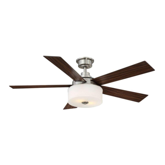
52” Lindbrook Thank you for purchasing our ceiling fan. This product has been manufactured with the highest standards of safety and quality. Ceiling Fan by Hampton Bay Date Purchased Table of Contents Store Purchased Safety Rules ....1 106-202 Model No. -
Page 5: Safety Rules
Safety Rules - Read and Save These Instructions To reduce the risk of electric shock, insure electricity has been turned off at the After making electrical connections, spliced conductors should be turned upward and pushed carefully up into outlet box. The wires should be spread circuit breaker or fuse box before beginning. -
Page 6: Unpacking Your Fan
Unpacking Your Fan Unpack your fan and check the contents. You should have the following items: Set of blades (5) Mounting plate Blade Attachment Hardware (16 Screws with lock washers) Canopy assembly Light kit Ball/downrod assembly Glass shade Electrical Hardware Coupling cover Receiver with 6 wire nuts (3 Plastic Wire Nuts) -
Page 7: Installing Your Fan
Installing Your Fan Provide Strong Support Tools Required Figures 1~3 are examples of different ways to mount the outlet box. Phillips screwdriver, straight slot screwdriver, step ladder and wire cutters. Recessed Ceiling Outlet Box Mounting Plate Mounting Options Figure 3 Outlet Box Note: You may need a longer downrod to If there isn't an existing NOM listed mounting box,... - Page 8 Hanging the Fan Remove the Motor Wires Pin in Locked Canopy Ring Positioon Ball/Downrod REMEMBER to turn off the power. Follow the Assembly steps below to hang your fan properly. NOTE: This ceiling fan is supplied with two types Ceiling Canopy of hanging assemblies;...
- Page 9 NOTE: If a longer downrod is needed, take out Remove the decorative canopy bottom cover Motor from the canopy. (Figure 8) the screw located in the hanger ball, lower the Collar Screw and Lock Washer hanger ball and remove the pin, remove all 3 (3 of 6 Places) Remove three of the six screws and lock pieces from the downrod and assemble them onto...
- Page 10 Installing Fan to NOM Listed the Electrical Box Outlet Box WARNING Mounting TO REDUCE THE RISK OF FIRE, ELECTRIC Screws (Supplied SHOCK OTHER PERSONAL INJURY. with Outlet Box) MOUNT FAN ONLY TO AN OUTLET BOX OR 120V SUPPORTING SYSTEM MARKED ACCEPTABLE Wires Groove FOR FAN SUPPORT AND USE THE MOUNTING...
- Page 11 Making the Electrical (Figure 15) Receiver to house supply wires electrical connections: Connect the black (hot) Connections Frequency Switch wire from the ceiling to the black wire marked "AC in L" from the receiver. Connect the white WARNING (neutral) wire from the ceiling to the white wire marked "AC in N"...
- Page 12 WARNING SUPPLY CIRCUIT CHECK TO SEE THAT ALL CONNECTIONS ARE Outlet Box TIGHT, INCLUDING GROUND, AND THAT NO Screws BARE WIRE IS VISIBLE AT THE WIRE NUTS. Ceiling Ground EXCEPT FOR THE GROUND WIRE. Mounting Conductor BLACK Bracket Finishing the Fan Outlet Box Canopy Installation...
- Page 13 Attaching the Fan Blades Close-to-Ceiling Mounting Remove the fan from the hook on the mounting bracket. Secure the canopy to the mounting Insert the blade through the slot in the housing. bracket with four screws included with your fan. Align the holes in the blade, the blade support (Fig.
- Page 14 Blade Balancing All blades are grouped by weight during assembly. Because natural woods vary in density, the fan may wobble even though the blades are weight Touching Ceiling matched. The following procedure should correct most fan wobble. Check after each step. Verify that all blades and blade bracket screws are secure (most fan wobble problems are caused by loose parts).
-
Page 15: Installing The Light Kit
Installing the Light Kit Installing the Mounting Plate NOTE the glass cap and decorative nut previously removed. Do not overtighten. (Fig. 21) BEFORE STARTING INSTALLATION, DISCON- Remove 1 of the 3 screws from the mounting NECT THE POWER BY TURNING OFF THE ring and loosen the other 2 screws. -
Page 16: Operating Your Transmitter
Operating Your Transmitter Installing the Battery: Restore power to the ceiling fan and test for proper operation. Install 12V MN21/A23 battery (included). To "HI, MED, LOW" buttons: prevent damage to transmitter, remove the battery These three buttons are used to set the fan if not used for long periods. - Page 17 Installing the Transmitter Speed settings for warm or cool weather depend on factors such as the room size, ceiling height, Holder number of fans, etc. Remove the two plugs from the holder. Note The reverse switch is located on the top of motor that the plugs have unique tabs that allows housing.
-
Page 18: Care Of Your Fan
Care of Your Fan Troubleshooting PROBLEM SOLUTION Here are some suggestions to help you maintain your fan. The fan will not start. Check main and branch circuit fuses or breakers. Because of the fan's natural movement, some Check line wire connections to the fan and switch wire connections in connections may become loose. -
Page 19: Specifications
Specifications FAN SIZE SPEED VOLTS AMPS WATTS N.W. G.W. C.F. 0.29 14.52 52.78 10.18 kg 11.30 kg 52” MED. 2.20' 0.37 31.22 97.33 (22.4 lbs.) (24.86 lbs.) HIGH 0.39 46.3 123.9 These are approximate measures. They do not include Amps and Wattage used by the light kit . Importer: SERVICIOS HOME DEPOT, S.
Need help?
Do you have a question about the Lindbrook YG336-BN and is the answer not in the manual?
Questions and answers