Table of Contents
Advertisement
Quick Links
Advertisement
Table of Contents

Related Manuals for Teagle TOMAHAWK C12

Summary of Contents for Teagle TOMAHAWK C12
-
Page 2: Safety First
SAFETY FIRST! 1. READ THE INSTRUCTION BOOK THOROUGHLY 6. SECURE THE PTO GUARD BY MEANS OF before attempting to operate or carry out any CHECK CHAINS to suitable points on the tractor maintenance on the machine. If you do not and machine to prevent the outer plastic shield from understand any part of this manual, ask your dealer rotating. - Page 3 INDEX Page Number SECTION 1 Installation Information SECTION 2 Control Desk Functions SECTION 3 Electronic Parts and Circuit Diagrams SECTION 4 Hydraulic Components SECTION 5 Oil tank Components and Hydraulic Pump SECTION 6 Solenoid Valve & Control Trouble Shooting SECTION 7 Solenoid Valve & Controls Repair And Adjustment...
-
Page 4: Section 1 Installation Information
1.5 ELECTRONIC CONTROL MAINTENANCE. Teagle Machinery Ltd should be contacted immediately if any problem is found with any aspect of the electronic controls during the warranty period. The correct course of action shall be advised by a member of the manufacturer’s Technical Staff. - Page 5 SECTION 2 CONTROL DESK FUNTIONS Section 2.1 Control Desk Connecting the control desk & junction box. Place the control desk in the cab and attach it in a convenient location using the suction cup. Plug the control desk into the power supply. Route the machine cable to the tractor auxiliary power socket ensuring it is kept away from the rear wheel and any pinch points between the PTO shaft and link arms.
- Page 6 Hold the sequence of buttons for 8 seconds until both the ‘bale chamber milling direction’ and ‘on’ LED’s illuminate. Release buttons and the LED’s should flash alternately. Using the automatic bale chamber speed control button to slow down, and the manual bale chamber speed control button to speed up, slow the bale chamber down to the point where it just stops.
- Page 7 When it is necessary to stop milling part way through a bale, always stop the bale chamber rotation and put it in reverse for a few seconds before stopping the mill rotor. This allows the material in the area around the mill rotor to be removed by the conveyor.
-
Page 8: Section 3.1 Electronic Controls
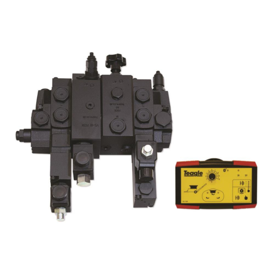
SECTION 3 ELECTRONIC PARTS & CONNECTION Section 3.1 Electronic Controls. Ref. Description Part No. Q’ty Associated components Part No. Q’ty Valve CV1525 HYD5430 Setscrew M8 x 20 FAS2627P 4 Spring Washer M8 FAS2353P 4 Bluetooth Control Kit EC2003 (Comprising Items 2 - 13) Control Desk Assembly EC2005 (Comprising Items 2 - 5) -
Page 9: Section 3.2 Connection Diagram
Section 3.2 Connection Diagram LED’s Bluetooth Speed connection status sensor LED’s Bluetooth card Power to oil cooler + VE Red -VE Black Power supply + VE Red Auxiliary -VE Black stop entrance Flashing Reverse Speed Forward Conveyor beacon sensor entrance entrance Flashing beacon... -
Page 10: Section 4 Hydraulic Components
SECTION 4 HYDRAULIC COMPONENTS Section 4.1 Identifying hydraulic slices components Ref. Description Part No. Q’ty. Associated components Part No. Q’ty. Main valve block (Items 1-6) HYD5430 Complete valve block seal kit HYD5435 Setscrew M8 x 20 FAS2627P Spring Washer M8 FAS2353P Outlet Slice HYD5436... - Page 11 Section 4.2 Identifying hydraulic slices components Notes:...
- Page 12 4.21 Outlet slice with pressurising valve HYD5436 Item No. Part No. Description. Qty. HYD5315 Outlet cover HYD5412 Pressurizing valve 4.22 Pressurising valve HYD5412 Figure 10. Pressurising valve HYD5412 Item No. Part No. Description. Qty. HYD5412. Pressuring Valve Assembly. Available in “O”...
- Page 13 4.23 Bale Chamber Reverse Slice. HYD5405 (seal kit no: HYD5316). Item. Atam Coil Description. Qty. HYD5306. Closure Plate. Seal Kit, HYD5316. “O” Ring. Seal Kit, HYD5316. “O” Ring. Seal Kit, HYD5316. “O” Ring. HYD5351 12 V Coil. HYD5352 Solenoid Cartridge. HYD5353 Cartridge, Coil &...
- Page 14 4.24 Bale Chamber Forward Slice. HYD5437 (seal kit no: HYD5438) Item No. Part No. Description. Qty. Seal Kit HYD5438 “O” Ring. HYD5411 Combined Bypass Relief Valve Not available Housing HYD5179 12V Coil HYD5313 Solenoid Cartridge...
- Page 15 4.241 Combined Bypass Relief Valve. HYD5411 (part of Item No. Part No. Description. Qty. HYD5411. Complete Assembly. Seal Kit, “O” Ring. HYD5340 “O” Ring. “O” Ring. “O” Ring. Notes:...
- Page 16 4.25 Inlet & flow divider HYD5439. (seal kit no: HYD5340) Item. Part No. Description. Qty. Seal kit HYD5340 “O” Ring. Not available Flow control cartridge Not available Housing HYD5314 Flow cartridge assembly...
- Page 17 .26 Conveyor Slice. HYD5441 (seal kit no: HYD5316) Item. Part No. Description. Qty. Seal kit HYD5316 “O” Ring. HYD5179 12V Coil HYD5313 Solenoid Cartridge HYD5306 Closure Plate...
- Page 18 4.27 End Cover With Conveyor Relief Valve. HYD5406 (seal kit no: Item. Part No. Description. Qty. Seal Kit, HYD5081. “O” Ring. Seal Kit HYD5081. “O” Ring. Seal Kit HYD5081. “O” Ring. Not Avail. Individually. Blanking Plug. Not Avail. Individually. Manifold. HYD5070.
-
Page 19: Section 4.3 Circuit Diagram
Section 4.3 Circuit Diagram Section 4.4 Summary Of Seal kits Ref. Description. Part no. Quantity. Seal kit part no. Complete valve block seal kit HYD5430 HYD5435 4.22 Pressurising valve HYD5412 HYD5413 4.23 Bale chamber reverse slice HYD5405 HYD5316 4.24 Bale chamber forward slice HYD5437 HYD5338 4.25... - Page 20 Section 4.4 Hydraulic Hoses & Fittings...
- Page 21 Description Part No. Q’ty. Associated components Part No. Q’ty. Lift Cylinder to Tractor Hose HYD2089 Bonded seal 1/2” HYD4204 Yellow spiral protection 1m HYD1975 DL1307 Red tape—flow direction 100mm Male coupling 1/2” BSP HYD1901 RH Lift Cylinder Hose HYD2088 1/4” BSP T Piece M/M/F HYD1930 LH Lift Cylinder Hose HYD2062...
-
Page 22: Section 5.2 Hydraulic Pump
SECTION 5. OIL TANK COMPONENTS & HYDRAULIC Section 5.1 Oil tank components Ref. Description Part No. Q’ty. Associated components Part No. Q’ty. Visual Level Indicator HYD5362 Oil Filler Cap Assembly HYD5360 Setscrew M5 x 20 FAS8903P 6 Locknut M5 FAS2328 Plain Washer M5 FAS2341P 12 Return Line Filter... - Page 23 SECTION 6. SOLENOID VALVE AND CONTROLS TROUBLE SHOOTING TOMAHAWK C12 FAULT FINDING CHART – PART 1 Symptom Fault Possible Solutions High power Bale fed too quickly into the rotor worn Reduce bale chamber speed. consumption. hammers. Bale chamber speed too high.
- Page 24 “ON” and “OFF” buttons the control desk from turning on. together for 2 seconds. Damage to electronic circuit. Contact Teagle Machinery Ltd. Conveyor Belt will not Hydraulic hoses incorrectly connected to Ensure the correct pairs of hoses are connected fold up or unfold from the tractor.
- Page 25 TOMAHAWK FAULT FINDING CHART – PART 3 Symptom Fault Possible Solutions Oil leaking from Clamping bolts loose. Check bolts through valve tightened to correct between slices of the torque specified in the maintenance section. valve. Interface seals damaged by either of the Replace damaged seals.
- Page 26 Bale chamber max and min values need adjustment usually indicated by a variable voltage outside the giv- en range. Control desk potentiometer or circuit board has failed - refer the control desk to Teagle Machinery Ltd for repair. Note: Control desks are available on an exchange basis to prevent any unnecessary down time.
- Page 27 6.6 Adjusting the pressure relief valve. To check the relief valve setting place an in line pressure gauge in the supply hose to the valve. Remove both hoses from the bed chain hydraulic motor and blank both hose ends. (3/8” BSP blanking plug for the hose fitting). Start the tractor and operate the bed chain with the bed chain speed control in its mid position.
Need help?
Do you have a question about the TOMAHAWK C12 and is the answer not in the manual?
Questions and answers