
Related Manuals for Walrus Pump TPR Series


Summary of Contents for Walrus Pump TPR Series
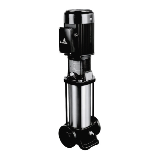
- Page 1 TPR Series Vertical Multistage Centrifugal Pump User Manual 日期 2017 10 25 核定 高添全 校對 李宗乾 製圖 吳盈慧 0 0 4 4 4 6 設變通知單 ISO 9001 Certified WALRUS PUMP CO., LTD.
-
Page 2: Ec Declaration Of Conformity
Walrus Pump Co., Ltd. Address: No.83-14, Dapiantou, Sanzhi Dist., New Taipei City 252, Taiwan Declare that the machinery described: Name : Water Pump Model : TPR Series Conform to the following directive: 2006/42/EC—Machinery directive 2014/35/EU—Low voltage directive 2014/30/EU—EMC (Electromagnetic compatibility) directive 2009/125/EC—... -
Page 3: Handling The Pump
Please read this instruction manual carefully before installing your new system as failures caused by incorrect installation and operation are not covered by the warranty. 1. Handling the pump When lifting the entire pump with motor, follow these instructions: Lift the pump in the motor flange by means of straps or the like. Fig. -
Page 4: Technical Data
3. Technical data 3.1 Operation condition Delivery liquids : non-viscous, non-flammable/explosive, not containing solid or fiber particles, and should not cause physical nor chemical damage to the pump. For viscosity larger than water, use pumps with a higher output if necessary. Whether a pump is suitable for a certain liquid depends on factors such as the liquid’s chlorine content, PH value, temperature and composition, among other factors. - Page 5 3.4 Minimum Inlet Pressure, NPSH Check the minimum inlet pressure under the following conditions: •The liquid temperature is high •Flow rate significantly larger than quoted maximum •The fluid requires a long sucking distance •Long pipes lead to the fluid inlet point Use the formula below to calculate the maximum suction distance of the pump: H = Pb x 10.2 –...
-
Page 6: Maximum Inlet Pressure
3.5 Maximum inlet pressure The following table shows the maximum permissible inlet pressure. However, the actual inlet pressure plus the pressure against a closed valve must always be lower than the maximum permissible operating pressure. If the maximum permissible operating pressure is exceeded, the conical bearing in the motor may be damaged and the life of the shaft seal reduced. -
Page 7: Installation
4. Installation 4.1 The pump must be secured to a horizontal, plane and solid foundation by bolts through the holes in the base plate. When installing the pump, follow the procedure below in order to avoid damaging the pump. Step Action Arrows on the pump base show the direction of flow of liquid through the pump. -
Page 8: Electrical Connection
5. Electrical Connection 5.1 The electrical connections must be performed by a qualified electrician in compliance with the required regulations. 5.2 Make sure that the supply voltages and frequencies matched with the electric motor rating plate. Provide suitable general protection against short circuits on the power line. 5.3 Before removing the terminal box cover and before any removal/dismantling of the pump, make sure that the electricity supply has been switched off. - Page 9 Start-up close open water flow 1. Close the isolating valve on the discharge 2. Remove the priming plug from the pump side of the pump and open the isolating head and slowly fill the pump with liquid. valve on the suction side. Replace the priming plug and tighten securely.
- Page 10 open a little open half open a little water flow water flow 5. Vent the pump by means of the vent valve 6. Continue to vent the pump. At the same in the pump head. At the same time, open time, open the discharge isolating valve a the discharge isolating valve a little.
-
Page 11: Maintenance
7. Maintenance Before starting work on the pump, make sure that all power supplies to the pump have been switched off and that they cannot be accidentally switched on. Pump bearings and shaft seal are maintenance-free. Motor bearings Motors not fitted with grease nipples are maintenance-free. Motors fitted with grease nipples should be lubricated with a high temperature, lithium-based grease. -
Page 12: Safety Protection
9. Safety Protection 9.1 Frost Protection Pumps that are not being used during periods of frost should be drained to avoid damage. 9.2 Scald Protection Do not touch the outer surface, when the pump is used for hot liquid transmission. 10. - Page 13 Maximum inlet pressure for TPR, TPR_S and TPR_N 50Hz 60Hz 1-2 → 1-36 10bar 1-2 → 1-25 10bar 1-27 15bar 3-2 → 3-29 3-2 → 3-15 10bar 10bar 3-31 → 3-36 3-17 → 3-25 15bar 15bar 5-2 → 5-16 5-2 → 5-9 10bar 10bar 5-10 →...
- Page 16 WALRUS PUMP CO., LTD. Web: www.walruspump.com...
Need help?
Do you have a question about the TPR Series and is the answer not in the manual?
Questions and answers