
Related Manuals for zapco ST-X DSP


Summary of Contents for zapco ST-X DSP
- Page 1 ST-X DSP Owner’s Manual Before operating the unit, please read this manual throughly and retain it for future reference.
- Page 2 (Knowledge from doing) There is absolutely no substitute for experience; that is a simple fact of life. Another simple fact is that ZAPCO has, for over forty years, been the leader in defining quality standards for the car audio industry.
-
Page 3: Table Of Contents
Inputs and Controls ..................ST-4X DSP Input Ends ................ST-6X DSP Input Ends ................Speaker Wiring of the Studio-X DSP Amplifiers ..........The ST-X DSP GUI Program ................Loading the GUI ..................Channel Setup ..................Delay ...................... Ch. Selection and Crossover .............. -
Page 4: A New Level Of Sound Quality
The challenge then, was to put Zapco's 40 plus years of experience to use in the development of an amplifier that would bring Zapco sound a line of products for every-day use and that everyone could afford. And the studio line is just that amplifier. -
Page 5: The Studio-X Dsp Amplifiers
• On-Board, Full Function, 6-ch or 8-Ch. Digital Signal Processing • High-pass and low-pass filters • Signal Delay • Phase (Polarity) control • 15 channels of parametric equalization on each channel • Optional BT Streaming (Bluetooth Port for external APTX HD Module) • And of course, Zapco sound quality... -
Page 6: Before You Start Your Installation
Any questions should be directed to your local ZAPCO dealer. Upgrading a Factory Stereo If you are upgrading a factory stereo the ST-X DSP amps have a separate speaker level input plug that senses current, so you do not need to run a turn-on wire. -
Page 7: Planning Your Power Connections
Ground to chassis +12 volt at Battery positive terminal Note: The ST-X DSP amplifiers have terminals that do not require connectors. You simply insert a bare portion of wire and tighten the connection with the supplied Hex tool. As the wire conforms to the connector the connection can loosen. -
Page 8: Wire Size
Some words about Power and Ground Note: The second most common cause of underperforming amplifiers is insufficient power current or a pour power connection. The most common cause of underperforming amplifiers is insufficient ground current or a bad ground connection. 12-volt current: Battery Power works only if it travels in a complete circuit from the battery positive terminal to the battery negative terminal. -
Page 9: Mounting Your Studio-X Dsp Amplifier
Mounting your ST-X DSP amplifier Mounting your Zapco amplifier is easy. Just keep in mind a few guidelines: • The amplifier can be mounted in any direction, on wood, metal, or carpet •... -
Page 10: Inputs And Controls
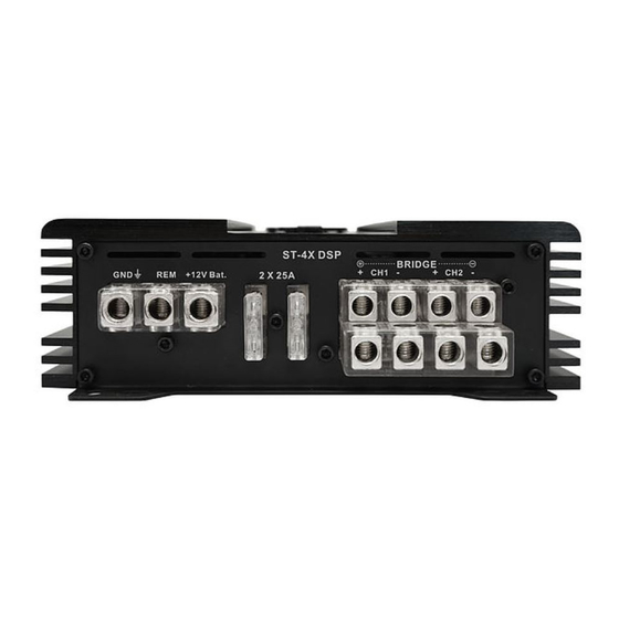
ST-4X DSP Input/Controls Ends The ST-4X DSP is a 4-Channel amplifier with on-board Digital processing for 6 channels to provide a processed output for a 2nd amplifier for bass. The input functions are described below: 1• Front (Ch 1/2 Channel) RCA Inputs 2• Rear (Ch 3/4) Channel RCA Inputs 3•... -
Page 11: St-6X Dsp Input Ends
ST-6X DSP Input/Controls Ends The ST-6X DSP has similar functions to the ST-4X DSP. The 6-Channel amp has on-board processing for eight channels to provide a processed preamp output. In addition to the extra channels, the ST-6X DSP has an optical input that can be accessed through the Mobile apps. -
Page 12: Speaker Wiring Of The Studio-X Dsp Amplifiers
• No speaker wires can be shorted to, or touching either ground or each other. This will put the amp into protect and may damage the amplifier • When bridging the left and right channels of any ST-X DSP amplifier, you use the left channel (Ch1) positive and the right channel (Ch2) negative, as... -
Page 13: The St-X Dsp Gui Program
GUI from the .exe file. Connecting the PC: Connect the PC to the ST-X DSP amp using the supplied USB cable. NOTE: The ST-X DSP GUI is very forgiving about PC Screen resolution. -
Page 14: Channel Setup
Working with the GUI Navigation bar: At the very top of the Screen you will find the Navigation bar. At the left is the connection indicator. When you open the program while you are connected to the DSP it will automatically link so you can use the GUI. If connection is lost it will show Not Linked so you can check the connections. - Page 15 Save, lets you save to a file on the PC or to a preset in the Processor. After you spend valuable time setting up and tuning the system, you won’t want to lose the setup, so you always want save your setup to one of the available presets. And for a backup and to keep extra presets you should save all your setup and tunes to a file on your PC.
-
Page 16: Delay
The Main GUI Screen The main screen has upper and lower sections. The upper section is where all the original system setup will take place, while the lower section contains the equalization controls and the frequency graph. Delay: At the left of the main GUI Screen is the Delay section. Since you can not sit directly in the center of the car, the program can delay the arrival time of near speakers so it will sound as though you are right in the middle of the car. - Page 17 In this example, the longer speaker distance is 70” so we subtract each of the other speakers from 70 and enter the results in the Delay chart. inch After you have entered the distances in you can click to see the delay in milliseconds.
-
Page 18: Selection And Crossover
Channel Selection and Crossover. The next section holds the You can select a channel to tune by clicking on the desired speaker in the car diagram/Delay section or by clicking on its box in the DSP Channel column. You can pick channels on at a time or you can pick them by pair. Double clicking the dot between a pair of channels links that pair. -
Page 19: Phase/Level
Phase/Level: The next section is for adjusting levels and checking Polarity to be sure all speakers are in phase with each other. There are a number of systems for checking System Phase. If the systems speakers are not all in phase there will be issues you can not fix by tuning. You can see the section on System Phasing to see one method of Phase checking. -
Page 20: Equalizer
Equalizer: The lower section of the GUI is devoted to equalization. Here are 15 bands of parametric equalization for each output channel and you can vary Frequency, Gain, and Q (the shape of the adjustment) for each band in several ways. Frequency: Each band is numbered. - Page 21 Gain: Gain can be adjusted by using the up/down arrows when the band’s EQ dot is highlighted. You can also click into the gain or Q rows of any band and adjust with the up/down arrows. You can move from one band to the next with the right/Left keyboard arrows.
-
Page 22: System Phasing
System Phasing: Before you start the equalization you want to be sure the system is phased properly. Below we offer one system to help you phase the system. You were promised more on polarity. Before equalization you should assure that all speakers are in phase as a system at the listening position. All speakers need to have the same polarity so they move the same direction at the same time. - Page 23 Once you have these phased you can bring in the mid-bass with the same process. Again, the focus should be high in the dash. If the mid-bass is out of phase with the tweeters and mids then they will pull the sound down toward the floor.
-
Page 24: Tuning - The Simple Rules
Tuning - The Simple Rules Before you can get what, you want you need to know what you want. In the graphs below, we look at some different response curves and what they mean and sound like. Keep in mind that these illustrations are NOT what your EQ graph looks like. They are what your RTA looks like. - Page 25 Problem Curve: Here is a problem curve. The small variations in blue are OK. They are 2dB or less and you likely will never hear them. However, the variations in the red circles are bad. While the ear is not so sensitive to dips in the response, it is very sensitive to peaks.
-
Page 26: Technical Specifications
Technical Specifications ST-4X DSP Power @ 4Ω: 4 x 65 watts THD @ Rated Power < 0.5% THD Power @ 2Ω: 4 x 95 watts Power Bridged @ 4Ω: 2 x 190W RMS Signal to Noise Ratio > 90dB THD + Noise < 0.2% Channel Separation >... - Page 28 APEX, Aprilia ITALY Since 1974 zapco.com...
Need help?
Do you have a question about the ST-X DSP and is the answer not in the manual?
Questions and answers