
Related Manuals for Bittium NeurOne


Summary of Contents for Bittium NeurOne
- Page 1 Page 1 of 191 NeurOne User Manual Date of issue: February 21st 2018 800581-2.11 NeurOne System User Manual.doc...
-
Page 2: Table Of Contents
IDEO PTION ........................41 ETTING YSTEM OPERATIONAL 4.9.1 Operations controlled by the Power button of Main Unit................43 4.9.1.1 Switching off NeurOne System ........................... 44 4.10 ................. 44 ANUAL ACTIVATION OF CALIBRATION FILES AND VERSION CHECK 4.11 ............................... 45 ONNECTING ENSORS 4.12... - Page 3 Remote control settings............................121 5.8.3 Appearance – user preferences ........................123 5.8.4 License settings ............................123 5.8.5 Institute settings ............................124 ................................125 ALIBRATION 5.9.1 Calibration adapters ........................... 125 5.9.2 Recommended calibration method ......................125 800581-2.11 NeurOne System User Manual.doc...
- Page 4 APPENDIX 1: PINOUTS OF TESLA AMPLIFIER KEL CONNECTORS ................. 147 APPENDIX 2: PINOUTS OF EXG AMPLIFIER D-CONNECTORS ..................148 APPENDIX 3: PINOUT OF NON-ISOLATED 8-BIT TRIGGER .................... 149 APPENDIX 4: PINOUT OF ANALOG OUTPUT ........................ 150 APPENDIX 5: NEURONE DATA FORMAT ........................151 ..................................151 INARY ILES ..................................
- Page 5 CTAVE SCRIPT FOR RECEIVING SAMPLE PACKETS APPENDIX 12: RAW MONITOR CONTROL PARAMETERS ..................... 185 APPENDIX 13: RESPONSE MONITOR CONTROL PARAMETERS ..................186 APPENDIX 14: MR CONDITIONAL STATEMENT OF COMPLIANCE FOR NEURONE TESLA AMPLIFIER, BATTERY PACK AND ACCESSORIES ................................188 MRI I ................................189 NFORMATION ...............................
- Page 6 +358 (0)17 581 7700 fax. +358 (0)17 580 0978 e-mail: bbs@bittium.com web: www.bittium.com Bittium Biosignals Ltd reserves all rights to improve, change and modify the products and the contents of the User Manual without prior notice. 800581-2.11 NeurOne System User Manual.doc...
- Page 7 Page 7 of 191 Connect only items that have been specified as part of the NeurOne System or that have been specified as being compatible with the NeurOne System. The assembly of the NeurOne System and modifications during the actual service life requires evaluations are the requirements of EN60601-1-1 standard still met.
-
Page 8: Introduction
Device. Users of the device should be acquainted with EEG measurements and measurement setups before using the device. In order to use the NeurOne System safely, all users must read this manual paying attention to the warnings and cautions. Explanations for the various symbols can be found in the following pages. -
Page 9: Symbols Used With The Device
Should any repair or replacement become necessary, we recommend that the device is delivered to your local distributor or Bittium Biosignals Ltd for service. The user of the product is solely responsible for any malfunction resulting from improper use, faulty maintenance, improper repair, damage or alteration by anyone other than Bittium Biosignals Ltd or their authorized service personnel. -
Page 10: Warranty
All warranties will be invalidated if unauthorized repairs are made to any parts of the overall system. The liability of Bittium Biosignals Ltd is limited to the repair of the product under warranty and specifically excludes consequential loss. The warranty covers all labour and parts associated with normal use. -
Page 11: General Handling
Page 11 of 191 2.1 Product Overview The NeurOne system includes sensitive electronics. Follow these general instructions when handling the system: Handle the device carefully. Be careful not to drop the device on hard surfaces. Be careful not to batter the device. -
Page 12: System Diagrams
Page 12 of 191 2.2 System Diagrams 800581-2.11 NeurOne System User Manual.doc... - Page 13 Page 13 of 191 Note: SPI and COM port are not yet available and will be enabled by future updates. 800581-2.11 NeurOne System User Manual.doc...
-
Page 14: System Functions
§ System consists of NeurOne Main unit (NeurOne Black) and up to 4 Tesla amplifiers which are used to collect polygraphic biosignals (EEG, ECG and EMG etc.). One Tesla amplifier can measure up to 32 unipolar and 8 bipolar channels. -
Page 15: Maintenance And Service
Do not try to open the device, the Power Supply, the cables or other sealed parts of the system. Only technical personnel, authorized by Bittium Biosignals Ltd, are allowed to open these parts, subject to the instructions given by Bittium Biosignals. -
Page 16: Software Installation
Page 16 of 191 3.1 System Requirements for the Computer The NeurOne PC Software requires the following hardware specifications as a minimum: Processor: Intel i5 3.0 GHz or better Screen Resolution: Full HD 1920x1080 Memory (RAM): 4 GB Graphics card:... -
Page 17: Installing The Neurone Pc Software
Page 17 of 191 3.3 Installing the NeurOne PC Software If you are upgrading to NeurOne PC Software v.1.5.x from NeurOne PC Software version older than 1.4.1.55 you must first install NeurOne 1.4.1.64 and manually back up your database. Manual database backup is done by copying NeurOneDB.mdf and NeurOneDB_log.ldf in database folder (default: C:\ProgramData\Mega... - Page 18 After extraction the installer automatically starts installation of a new database server instance Then opens the license terms page. (1) Check “I accept license terms.” and (2) click Next >. If Microsoft Update is requested click Next> (DO NOT CHECK THE CHECKBOX) 800581-2.11 NeurOne System User Manual.doc...
- Page 19 Page 19 of 191 At Product updates click Next> On the feature selection page make sure all features are selected and click Next >. 800581-2.11 NeurOne System User Manual.doc...
- Page 20 Page 20 of 191 On the Instance configuration page (1) ensure that the Named instance and Instance ID fields are set to value NEUROSQLEXPRESS and (2) click Next > On Server Configuration click Next > 800581-2.11 NeurOne System User Manual.doc...
- Page 21 Page 21 of 191 In database engine configuration leave selection to default. Click Next >. 800581-2.11 NeurOne System User Manual.doc...
-
Page 22: Visual C++ 2015 Redistributable Installation
Click Close to exit SQL Server 2014 Setup . 3.3.2 Visual C++ 2015 Redistributable Installation If the Visual C++ 2015 Redistributable x64 is not installed, the installer will install it next. Allow changes by clicking Yes. 800581-2.11 NeurOne System User Manual.doc... -
Page 23: Neurone Software Installation
The installation continues now with the actual installation of NeurOne software. Click Next >. If former version of NeurOne PC SW is installed on the PC and it is detected the setup program asks to choose (1) either existing or new database for installation and (2) Click Next >. - Page 24 (2) Click Next >. Note that if you install Tesla filters and you have any pre- existing protocols using EXG filters, the software will (with your permission) try to convert those protocols to use Tesla filters. 800581-2.11 NeurOne System User Manual.doc...
- Page 25 Page 25 of 191 Now the Installer is ready to install NeurOne Software. Click Install and all NeurOne program files are installed to the folder C:\Program Files\Bittium Biosignals Ltd\NeurOne\. During the installation the calibration files (*.hbc) of the amplifiers found on the installation media are copied to the sub-folder HBC in Misc data folder.
-
Page 26: Neurone Database Conversion
3.3.4 NeurOne Database Conversion If you have an older NeurOne version (1.3.x) that uses SQL Server 2005 for database, you need to convert the NeurOne database file so that it will work with new version of NeurOne. First install SQL Server 2014 express with management studio to your computer. This is not contained in the NeurOne installer. - Page 27 C:\ProgramData\Mega Electronics Ltd\NeurOne\ or C:\ProgramData\Mega Electronics Ltd\NeurOne64\ Select the NeurOne database file NeurOneDB.mdf. Make sure that you make backup form the database files before you do this conversion. This is done so that you just copy the NeurOneDB files to some secure location before conversion.
- Page 28 NeurOne software. Right-click the attached database, select task\detach and click OK. Database will disappear from under the system database and is now ready for use in the new version of NeurOne software. Close the SQL server management studio and start NeurOne.
-
Page 29: Installing Neurone Video Option
You can configure the TCP/IP settings in two ways: You can dedicate the Ethernet port for NeurOne use and set the IP address and Subnet mask in the General tab. For an example, see the figure on the left hand side. -
Page 30: Neurone Ip Address
Network Connections, and follow the above instructions. 3.5.1 NeurOne IP address The following table defines the control IP address of NeurOne Main unit when used as Stand-alone (without SyncBox) and as Master/Slave Main unit with SyncBox:... -
Page 31: Hardware Installation
Page 31 of 191 The NeurOne system consists of: Setup A: o Main Unit, model: Extended o Amplifiers (1 – 4 pcs) Model: EXG amplifier or Tesla amplifier o Main Unit power cable (with AC/DC transformer) o Amplifier power cables (1 – 4 pcs) o Optical cables (between Main Unit and Amplifier, 1 –... -
Page 32: Main Unit - Model Extended
5. Power Indicator Led (AC) – Indicates that the Main Unit is connected to mains power (green). 6. Power Button (green) – ON/OFF-switch, selecting display mode Default mode “NeurOne, press button for info” Tesla amplifier voltages Trigger counters ... -
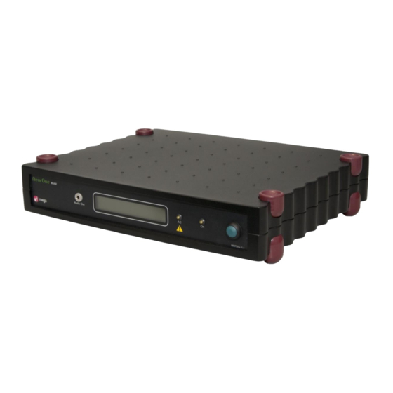
Page 33: Main Unit - Model Black
2. Power – medical approved power supply (100 – 240 vac in, 12 vdc out) 3. Trigger – isolated triggers a and b (rj11) 4. Analog output – analog output for 16 channels (configurable from neurone pc software) 5. Spi – spi connection (not yet available) 6. -
Page 34: Main Unit - Model Black High
See chapter 4.9 for instructions on how to connect cables to the connectors. 4.3 Main unit – model Black High The front panel of the Main Unit has following components: 1. Audio Out – 3.5 mm connector for headphones in audio applications. 800581-2.11 NeurOne System User Manual.doc... - Page 35 2. Power – medical approved power supply (100 – 240 vac in, 12 vdc out) 3. Trigger A – isolated trigger a (rj11) 4. Analog output – analog output for 16 channels (configurable from neurone pc software) 5. Trigger B – isolated trigger b (rj11) 6.
-
Page 36: Exg Amplifier
Page 36 of 191 4.4 EXG Amplifier A single NeurOne EXG amplifier offers 32 monopolar channels and 8 bipolar channels, allowing up to 40 available measurement channels. You can use either the safety connectors in the front panel or the D-connectors in the back panel for each channel. -
Page 37: Tesla Amplifier
4. Bipolar/Module – 25 pin D-connector for bipolar channels and external sensors. Each Amplifier in NeurOne system has an identification label in the left upper corner of the front panel. The first Amplifier 1 of the system is labeled “1”, Amplifier 2 is “2” etc…... -
Page 38: Jackbox
4.14. 4.6 JackBox NeurOne JackBox is meant to be used with Tesla amplifier and when using TMS cap (each cap having own JackBox). JackBox provides inputs for two amplifier, master and slave. The master amplifier has inputs 1 – 40 and slave inputs 41 – 80. -
Page 39: Bipolar Connection Box
JackBox can be piled with two Tesla amplifiers as shown in the following picture: 4.7 Bipolar Connection Box NeurOne Bipolar Connection Box is meant to be used with Tesla amplifier to measure external sensors such as GSR, accelerometer, Respiration and bipolar EMG, EEG and ECG signals. -
Page 40: Video Option
All possible configurations (using internal DIP switches) for Bipolar Connection Box are explained in Appendix 9. SEE APPENDIX 9 BEFORE CHANGING CONFIGURATION IN BIPOLAR CONNECTION BOX! 4.8 Video Option The NeurOne video option consists of: Video camera (Full HD, audio input, HDMI output) 800581-2.11 NeurOne System User Manual.doc... -
Page 41: Getting Neurone System Operational
2. All NeurOne system (AC powered) devices shall be powered through the isolation transformer! 3. Charge the Battery Pack(s) of NeurOne system according to the instructions in chapter 4.14.5 Charging the Battery Pack. 4. Connect each EXG amplifier power cable to the Amplifier power supply connector on the Main Unit. - Page 42 15. Optional: connect external microphone to external microphone socket of Video trigger interface cable 16. Turn on the PC and start NeurOne PC SW. When requested, input your license information or copy and paste them from license file 17. Create test protocol for the measurement purposes. Set trigger for video if its used.
-
Page 43: Operations Controlled By The Power Button Of Main Unit
Page 43 of 191 4.9.1 Operations controlled by the Power button of Main Unit NeurOne Main Unit Power button controls the following operations: Power ON /OFF, Display mode change and FW upgrades to the amplifiers, SyncBox and Digital out. The figure below describes the principle of these features and display layouts. -
Page 44: Switching Off Neurone System
In case of missing calibration file the following procedure is required: 1. By default NeurOne calibration file(s) of the amplifier(s) are located in the Hbc subfolder in Misc data folder:... -
Page 45: Connecting Sensors
1. Stimulus trigger 2. Video synchronization trigger 3. Mute trigger For more details on setting up the triggers in the NeurOne PC Software see Chapter 5.8.1 Core - System Settings. Trigger signal requirement: TTL pulse. 4.12.2 Non-Isolated 8-bit Trigger in There is a 15-pin D-connector on the Main Unit providing 8-bit non-isolated trigger input and output, labeled “Trigger I/O”. -
Page 46: Analog Output
The output range of the NeurOne analog output is 0 – 2.5 V (zero level 1.25 V). For making your own analog output cable, please refer to Appendix 4 or contact Bittium Biosignals for more information. -
Page 47: Ac Adapters
Page 47 of 191 4.13 AC Adapters Use only the AC adapter delivered with NeurOne system. Available AC adapter models for NeurOne Main unit are: Powerbox AC power adapter, EXM 80 5118 PROTEC POWER, Model: PMP60-12 FSP GROUP INC. AC/DC Adapter, FSP030-RCAM (only for model Black) 4.14 Battery Pack Use... -
Page 48: Battery Pack 12 V For Exg Amplifier
(below 6 V). 2. Power Switch 3. Power Out / Charger – To Tesla amplifier or to Battery Charger for Battery Pack The battery type of Battery Pack 6 V is lead acid. 800581-2.11 NeurOne System User Manual.doc... -
Page 49: Battery Pack 7.2 V For Tesla Amplifier
First, make sure that the power of the Battery Pack is switched off. Connect the Battery Charger to the Battery Pack and the Battery Charger to mains power. The indicator led (1) on the Battery Charger is red during charging. When the Battery Pack reaches 800581-2.11 NeurOne System User Manual.doc... -
Page 50: Battery Pack 6V Of Tesla Amplifier
Battery Charger is blinking green during charging. When the Battery Pack reaches full capacity, the indicator led glows green. Typical charging time is approximately 5 hours. Depending on the depth of discharge and operating temperature, the Battery Pack 7.2V provides 500 discharge/charge cycles. 800581-2.11 NeurOne System User Manual.doc... -
Page 51: Connecting The Battery Pack
Battery Pack. Connect the Battery Pack 12V to the EXG Amplifier(s) or Battery Pack 6V to Tesla amplifier(s) with the appropriate Amplifier Power Cable. Make sure NeurOne Main Unit is turned on. Turn the Battery Pack on. -
Page 52: Special Configurations Using Syncbox
Page 52 of 191 4.15 Special configurations using SyncBox By using the NeurOne SyncBox it is possible to run several NeurOne Main units (all models) in parallel providing expandable system up to 1200 channels. Example of 240 channels NeurOne system with two Main Units synchronized by NeurOne SyncBox is... - Page 53 (Master included). This trigger starts the actual data acquisition simultaneously on all channels defined in measuring protocol. The front panel of the NeurOne SyncBox has following components: 1. Trigger – Trigger button. 2. LED (BNC) – Indicates that external clock is detected in BNC connector.
- Page 54 Connect Ethernet cable from Main Unit Master to port 2 Connect Ethernet cable from Main Unit Slave to port 3 Follow the instruction of chapter 4.9 to finalize NeurOne system setup for measurement. Turn SyncBox power on first. After that start Master Main Unit and all Slave Main Units and finally all amplifiers.
-
Page 55: Using The Software
Page 55 of 191 Double click the NeurOne icon to start NeurOne software. Pass the login dialog by clicking OK. The software is controlled with tabs which are located on the upper part of the main window. They divide the functions of the software into groups: NeurOne, Person, Project, Protocol, Measurement, Results, Tools and Settings. - Page 56 The software asks you to confirm or cancel the deletion. Person List: A list of all persons entered into the NeurOne database. The fields can be sorted by clicking the label of the wanted column. Clicking a name selects a Person from the list and displays the Person details on the right.
-
Page 57: Projects
5.2 Projects The Project is a convenient way to group and sort out your measurements. You can create a Project e.g. for each new study you conduct. When NeurOne PC SW is started, Project is preselected according to previous application run. -
Page 58: Protocol - Measurement Protocol
Page 58 of 191 5.3 Protocol - Measurement Protocol The Protocol tab is the most important entity of the NeurOne software. The Protocol defines all the details of a measurement session, including the amount and type of signal inputs. It also defines e.g. how the measured signals are filtered in hardware and how they are shown on screen during the measurement. -
Page 59: Main Properties - Protocol Subtab
Page 59 of 191 Export – Export the Protocol to an XML file, e.g. to another installation of NeurOne. Export is possible when the selected Protocol is not in Edit mode. The Protocol subtabs are Protocol, Inputs, Real-time Out, Montage and Plug-Ins. - Page 60 Amplifiers in a measurement setup, the input numbers of the Amplifiers are the following: Amplifier 1: Inputs 1 – 40 Amplifier 2: Inputs 41 – 80 Amplifier 3: Inputs 81 – 120 Amplifier 4: Inputs 121 – 160 800581-2.11 NeurOne System User Manual.doc...
- Page 61 Range As Calibrated – This field is for external signal calibration. The content of the field is actual min; actual max (note the separator is semicolon between the numbers). Those numbers are true signal values corresponding to the measured min and max 800581-2.11 NeurOne System User Manual.doc...
-
Page 62: Real-Time Out
The “Real-time Out” subtab provides controls for Audio Output, Analog Output and Digital Output. Audio Output can be used in parallel with either Analog Output or Digital Output. Either Digital Output or Analog Output can be select for output use at a time. 800581-2.11 NeurOne System User Manual.doc... - Page 63 Data sampled with the set sampling frequency will be fed directly to the analog output. It is recommended to take care of appropriate anti-aliasing filtering before A/D conversion in the target system. 800581-2.11 NeurOne System User Manual.doc...
-
Page 64: Digital Out Settings
Exports the list of Digital OUT channels as *.txt file to the desired target folder. Settings of Digital OUT. 5.3.4.1 Digital OUT settings The UI of Digital OUT settings contains the graphic presentation of SyncBox rear panel for Main Unit selection. 800581-2.11 NeurOne System User Manual.doc... - Page 65 Page 65 of 191 Discover button scans the NeurOne system in order to find out if SyncBox is available and the number of Main Units in the system and updates that parameter on the UI. Select the desired Main Unit for Digital OUT definition (the parameter: Selected Main Unit).
- Page 66 It’s the last packet emitted when measurement hardware is stopped. * The Join packet is sent by the system receiving NeurOne digital out data. Main purpose of this packet is to enable MeasurementStart packet re-emission by NeurOne in cases where the receiver system comes online after NeurOne measurement has already been started.
-
Page 67: Montage
Do Not Send Triggers 5.3.5 Montage The “Montage” subtab is used to create the default Montage for the Protocol to be used during the recording. This Montage will be shown as “default” when selecting/changing the Montage. 800581-2.11 NeurOne System User Manual.doc... - Page 68 Finally edit the desired default Montage of the Protocol to be used when Protocol is started. Later on, additional montages can also be defined in Tools | Montage Pool. Click “Next” to enter the last phase of the Protocol creation: to the subtab called “Plug- Ins”. 800581-2.11 NeurOne System User Manual.doc...
-
Page 69: Plug-Ins
5.3.6.1 Audio Output Control If there is Audio Output Control defined on this page it is possible to change desired inputs to be played on left and right audio channel during the measurement. 800581-2.11 NeurOne System User Manual.doc... -
Page 70: Data Writer
5.3.6.2 Data Writer Data Writer plugin is responsible for recording the measured signals (and events) to disk (for details on the data format, see Appendix 5: NeurOne Data format). It has the following settings: Name – Name of the Data Writer File Size Limit (Mbytes) –... -
Page 71: Raw Signal Monitor
X-Axis length (s) – The time range of the monitor view in seconds (default 10 s). Accept stimulation triggers – If set on, the monitor shows incoming stimulation triggers. Accept video triggers – If set on, the monitor shows incoming video triggers. 800581-2.11 NeurOne System User Manual.doc... -
Page 72: Response Monitor
Accept 8-bit triggers – If set defined 8-bit trigger combination are accepted. Accepted trigger combination are selected on the control on the right of the tab (refer Raw signal monitor). Port SyncBox EXT – SyncBox Ext trigger type selection. 800581-2.11 NeurOne System User Manual.doc... - Page 73 End padding (samples) – additional buffer for data after response. TMS Correction The TMS (transcranial magnetic stimulation) artefact removal in NeurOne consists of two operations: TMS Mute and TMS Decay. TMS Mute – This operation replaces a section of the signal with a ramp, starting 1 ms before the trigger zeropoint.
- Page 74 = -50, b = -400 gives the same result as a = -400, b = -50. In the figure below, Left: original EEG response to a TMS pulse. Right: Response after using software TMS Mute with a duration. 800581-2.11 NeurOne System User Manual.doc...
-
Page 75: Video Monitor
Recommendation: Use PAL settings according to the screenshot. 5.3.7 Finalizing the Protocol After you have completed Protocol definitions on all subtabs (create or edit) click OK button to complete this procedure. 800581-2.11 NeurOne System User Manual.doc... -
Page 76: Measurement
The Measurement tab is the page from where all the measurements using the NeurOne software are started. In order to be able to access the Measurement tab, user needs to have selected a Person, a Project and a Protocol for the measurement. The selected Person, Protocol and Project should be visible in the status bar of the software. - Page 77 “Simulation” - If checked the simulation measurement asks the data file to be simulated. Simulation starts also if NeurOne HW is not connected to the PC. “Restore Monitors” – Opens the monitors which have been closed during the measurement session.
-
Page 78: Monitors
5 minutes to replace a fresh battery (battery fork cable required). If the 5 minute countdown elapses, the measurement is stopped to ensure data integrity. * *) This feature is available only with new Tesla amplifier and batteries (see chapter 4.14.1) 5.4.1 Monitors 800581-2.11 NeurOne System User Manual.doc... -
Page 79: Raw Monitor Properties
Page 79 of 191 NeurOne software measurement view is based on a unique monitor structure, where each monitor (raw, response and impedance) is totally scalable and movable. This feature allows monitor windows to be placed in different screens in a multiple displays setup and enables monitors to be hidden, placed on top of each other, stacked, minimized or maximized. - Page 80 Positive down (all curves): Positive values below the 0 line. Last values►: Show all: Numeric values of data of all channels are shown. Hide all: Numeric values are hidden. Show for calibrated: Shows numeric values of data of channels with external signal calibration. 800581-2.11 NeurOne System User Manual.doc...
- Page 81 Line color: Color of the channel definition in the measurement (does not affect the default color set in the Protocol tool). Notch filter: Sets Notch filter on/off for the channel. Display filter: Sets selected display filter for the channel. 800581-2.11 NeurOne System User Manual.doc...
-
Page 82: Response Monitor Properties
Montage selection: Drop down menu for changing the active Montage View selection: Four view modes are available: Default – NeurOne basic response monitor Grid - Shows responses in a two-dimensional grid Topography – Topography plot with a head image ... - Page 83 In response monitor Auto-align now operates on average response only if it's visible. Otherwise single response is used. Polarity►: Positive up (all curves): Positive values above the 0 line. Positive down (all curves): Positive values below the 0 line. 800581-2.11 NeurOne System User Manual.doc...
- Page 84 Show limits : On/off selection: shows the rejection limits. Seek after [ms] : Time period from trigger after which rejection seek is active. Rejection limits are now remembered by curve name and not forgotten when the montage changes. 800581-2.11 NeurOne System User Manual.doc...
- Page 85 Set Y-axis range (same signal type): Y-axis range to all channels with same signal type according to min – max settings. Auto-align►: Off: Auto-align disabled Bind to single: Forces the single responses to be shown on the monitor. 800581-2.11 NeurOne System User Manual.doc...
-
Page 86: Impedance Test
To start an impedance test, click Start (Impedance Test) button. Impedance monitor will be opened on the window and the impedance results of all channels selected for 800581-2.11 NeurOne System User Manual.doc... - Page 87 In this mode it is possible to move the electrodes to the desired location and finally save the layout to be used during next measurement session. For this picture view background image “Head.bmp” is available in NeurOne program data folder. For most of standard electrodes the location is calculated when this image is used as background.
- Page 88 Impedance test results are saved in text file into person data folder (primary location for the impedance results). The text file name syntax is ImpedanceData-[yyyy]-[mm]-[dd]T[hh][mm][ss].txt. The final location of impedance results file is determined as follows: After Impedance test: 800581-2.11 NeurOne System User Manual.doc...
- Page 89 At application exit the warning is shown if there are any unassociated impedance files that were created during the application run time o By choosing Yes the explorer window is opened to the affected person data folders 800581-2.11 NeurOne System User Manual.doc...
-
Page 90: Audio Output Control
5.4.4 EEG recording – entering comments For basic EEG recording is the raw monitor used and it works as described in section 5.4.1.1. Comments can be added in “Comment Entry” dialog as follows: 1. Press space button. 800581-2.11 NeurOne System User Manual.doc... - Page 91 On the right side of the dialog there is General list for comments, which are stored into the database. Move the comments between Session and General list as follows: Move selected comment from General list to Session list. Move selected comment from Session list to General list. 800581-2.11 NeurOne System User Manual.doc...
-
Page 92: Ep Recording
Single button. The response counters are enabled from the General button and the values are shown on the right side of the curve. For saving responses, click Record responses button on the Response monitor. 800581-2.11 NeurOne System User Manual.doc... -
Page 93: Video Recording
First make sure the video camera and the video trigger box are connected according the schema on the chapter 4.8 Video Option. Add Video Monitor to Protocol with the following settings: • Video device: XI 100D USB-HDMI Video • Video resolution: 720 x 576 @60,241 800581-2.11 NeurOne System User Manual.doc... -
Page 94: Viewing The Results
In order to access the result tab, a Person needs to be selected. After selecting a Person, the list of stored sessions corresponding to this Person will be updated on the results tab. 800581-2.11 NeurOne System User Manual.doc... - Page 95 Edit – Edition of measurement details ( Exam code, Technician, Medication, Notes) the of selected measurement. Move/Archive Copy – Provides features either move or archive copy of Session data. NeurOne Import – Import of NeurOne data. 800581-2.11 NeurOne System User Manual.doc...
- Page 96 Biolink Import – Import of Biolink data. EDF+ Export – Export to EDF+ data format. When NeurOne exports data measured with 24 bit ADC resolution it scales signals: AC mode: data is exported to 16 bit data with 0.1 uV resolution (full scale of EDF+ signal: +/- 3.27 mV)
-
Page 97: Review Window
Remove selected session from Export list Export selected sessions 5.5.1 Review window Review window provides data inspection tools with scaling, zooming and panning as follows: S+ : Increase value range sensitivity (for quick scale adjustment). 800581-2.11 NeurOne System User Manual.doc... - Page 98 Cursors move: click the left mouse button on top of the cursor. Keep the left button down and move the cursor to desired location. Selecting cursor opens Data window with Cursor data tab selected (as default). 800581-2.11 NeurOne System User Manual.doc...
- Page 99 Shows the information about the events of the recording. On this tab it is possible to set and remove the event filter in order to get the list of desired events. Buttons Configure and Remove (event filter). 800581-2.11 NeurOne System User Manual.doc...
- Page 100 New: creates a new event at the current tracking cursor position. Delete: deletes the selected event(s). Generate…: creates new events based on signal changes. Split…: splits 8-bit markers to multiple markers based on given bit boundaries. 800581-2.11 NeurOne System User Manual.doc...
- Page 101 Event generation is based on defined signal change speed of selected channel or if signal of the selected channel exceeds or goes under defined threshold level. Pressing Generate on NeurOne event editor opens Marker creator control with the following definition parameters: Source channel: defines the channel for event generation.
- Page 102 Type: type of trigger to be generated. Source port: source port of trigger to be generated. NeurOne event editor provides following definition functions: Preview: displays the pre-view of markers generated using set parameters. Generate: generates new markers for the data using set parameters.
- Page 103 Review window for choosing desired data area. In addition, visible data area can be moved using following shortcut keys: PgUp – to left and PgDn - to right. 800581-2.11 NeurOne System User Manual.doc...
-
Page 104: Viewing Data With Video
Video review informs the total duration of video and the time stamp of the current video frame. Add comments: open comment entry dialog from menu, space button or mouse right click. Comments are available also in exported data, for ex. when inspecting data with MATLAB. 800581-2.11 NeurOne System User Manual.doc... -
Page 105: Recorded Responses
Data S N – Start trigger of N stored response data block RES S N – Start trigger of N stored actual response RES E N – End trigger of N stored actual response 800581-2.11 NeurOne System User Manual.doc... -
Page 106: Tools For Universal Input Groups, Montages And Display Filters
This average can be used as reference. On the left side of the Input Group Pool page is the list of available Input Groups. Left side contains the following fields: Name – Name of Input Group. 800581-2.11 NeurOne System User Manual.doc... - Page 107 Add inputs to the selected Input Group. The button is active, when Input Group is selected on the list of Input Groups. Remove the selected inputs from selected Input Group. Add several inputs to the selected Input Group. 800581-2.11 NeurOne System User Manual.doc...
-
Page 108: Montage Pool
On the left side of the Montage Pool page is the list of available montages. Add new Montage to the list of Montages. Remove selected Montage from the list and from database. Import new Montage from XML file. Export selected Montage to XML file. 800581-2.11 NeurOne System User Manual.doc... - Page 109 Add channel (curve) to the selected Montage. The button is active, when Montage is selected on the list of Montages. Remove the selected channels from selected Montage. Add several channels to the selected Montage. Create new Montage using selected channels. 800581-2.11 NeurOne System User Manual.doc...
-
Page 110: Display Filter Pool
Otherwise use same sampling frequency as in the protocol. For Response monitor use: Set sampling frequency of the display filter as defined in the protocol. Common predesigned IIR filters shipped with NeurOne PCSW are not visible in filter designer. Recommendation: For high sampling rates (>2k) design SOS cascade filters with MATLAB. - Page 111 Add new Display filter to the list of display filters. Remove selected Display filter from the list and from database. Import new Display filter from XML file. Export selected Display filter to XML file. Undo the latest change Redo the latest change 800581-2.11 NeurOne System User Manual.doc...
- Page 112 Length – Number of points in FIR filter Passband Ripple – Value for pass band ripple in dB Stopband Attn. – Value for stop band attenuation in dB Transition Width – Transition width (in Hz) from pass band to stop band 800581-2.11 NeurOne System User Manual.doc...
-
Page 113: Accessing Settings
Protocol (note the sampling rate limitations for raw monitor). 5.8 Accessing settings The Settings tab is used for controlling all the settings related to the NeurOne Main Unit and the Amplifiers. Also software settings, including data connections, file systems and networking and license management. -
Page 114: Core - System Settings
NeurOner manager is opened. See more in the following chapter 5.8.1.1 NeurOne manager. NeurOne section has also controls tabs for trigger inputs A, B, 8-bit trigger, Amplifier Muting. An incoming trigger launches a trigger out pulse if trigger out is allowed in PC Software. - Page 115 Magnetic stimulus input mute (Switch) – If set allows the switches are muted, when mute trigger comes in. Mute start difference - Time difference (in µs) between switch mute and main amplifier mute. If value is positive switches are muted first. 800581-2.11 NeurOne System User Manual.doc...
- Page 116 SyncBox EXT Trigger port, minimum input pulse length (µs) – Minimum length of accepted trigger pulse. SyncBox connection – If Automatic SyncBox discovery is set, NeurOne software automatically checks during the measurement start-up if SyncBox is available. If Choose manually is set, the user selects either SyncBox system (NeurOne system with SyncBox) or Standalone system (NeurOne system without SyncBox).
-
Page 117: Neurone Manager
5.8.1.1 NeurOne manager Manager… button opens NeurOne manager providing the topology of active NeurOne system. The topology shows PC, Main Unit and all amplifiers connected to the Main Unit as well as SyncBox if connected to Main Unit(s). Refresh and Setting buttons are on the left top corner of the window. - Page 118 Press open. The Upgrade starts. Main Unit display shows the progress of the upgrade. When ready “NeurOne - press button for info” text is on display of Main Unit. Information of connected Amplifier When mouse pointer is placed on the Amplifier icon the tooltip shows serial number, firmware version and battery voltage of chosen Amplifier.
- Page 119 Amplifier icon. Upgrading Amplifier firmware o Make sure Amplifier(s) are on and connected to NeurOne Main Unit. o Press the power button according to the instructions in chapter 4.9.1 Operations controlled by the Power button of Main Unit.
- Page 120 1.3.x.y and older. NeurOne manager – table form Pressing Shift key and Manager… buttons simultaneously NeurOne manager in table form is opened. It shows available Main Units and all amplifiers connected to the Main Units. Serial number, IP Address, Firmware version, Device type and Battery status is shown if available.
-
Page 121: Remote Control
Update firmware… initiates the firmware update procedure to NeurOne Main Unit. NeurOne Manager table view shows all devices or only Main Units or Amplifiers. Refresh devices update the table view. Report copies the information on the table to clipboard. - Page 122 Page 122 of 191 Network Interface - The network interface the remote control listens to. If you control NeurOne from the same computer, choose 127.0.0.1. Else choose the interface that's connected to your LAN. This setting has no default value.
-
Page 123: Appearance - User Preferences
The options section below the license section displays the current configuration and the enabled options. Edit your institute name and license key information to the corresponding fields and click “Set”. 800581-2.11 NeurOne System User Manual.doc... -
Page 124: Institute Settings
The Institute subtab is used to fill in institute information placed into reports created with the NeurOne system. Edited information will be stored automatically to the database. Besides information, you can also select a logo to be placed on the reports. -
Page 125: Calibration
HBC folder). Please, refer the chapter 4.10 Manual activation of calibration files and FW version check. If there is a need for calibration, NeurOne Tesla amplifier/EXG amplifier gain and offset (in AC and DC) are recommended to be calibrated as combination of available internal and external calibration method. - Page 126 10. Current calibration values Offset DC, Gain DC, Offset AC and Gain AC for all channels of the calibration file are shown. 11. Press Select all button to select all channels for calibration or select desired channels. 800581-2.11 NeurOne System User Manual.doc...
- Page 127 Offset. Uncheck Use internal test signal. Run the offset calibration with setting shown below. 14. The reminder message (shown below) for the user to check that the adapter is attached as instructed in step 2. 800581-2.11 NeurOne System User Manual.doc...
- Page 128 17. When AC and DC offset calibration is completed close the window. 18. The calibration values of Offset DC and Offset AC are updated in Amplifier calibration windows according to measurement data. 800581-2.11 NeurOne System User Manual.doc...
- Page 129 25. When AC and DC gain calibration is completed close the window. 26. The calibration values of Gain DC and Gain AC are updated in Amplifier calibration windows according to measurement data. 800581-2.11 NeurOne System User Manual.doc...
- Page 130 Therefore, it is not recommended to use such a calibration file. Headbox calibration files used in the measurement are now copied into a zip file in the measurement folder. 800581-2.11 NeurOne System User Manual.doc...
-
Page 131: Getting Help
Page 131 of 191 5.10 Getting help The NeurOne tab of the NeurOne software provides the user with help on using the software through the user manual (opens as an –pdf file, please make sure you have the free Adobe Acrobat –reader installed, ask Bittium Biosignals for more information) and information on the software. -
Page 132: Example Case: P300
Add, Add Many and Delete buttons accordingly. If you already have a protocol for your cap, you can import the protocol with the Import button. When you have finished filling in the information, click “Next” to proceed. 800581-2.11 NeurOne System User Manual.doc... - Page 133 The right hand side holds the default (starting) parameters for the measurement. These can be changed at any time using the measurement and only affect the way the data is displayed. You can set 800581-2.11 NeurOne System User Manual.doc...
- Page 134 Add to make a new input group and name it A1 A2. Next, set the calculator to be average. After this, add two inputs using Add button on the right hand side window. Now these inputs must have the same name as the input name in the 800581-2.11 NeurOne System User Manual.doc...
- Page 135 StimTracker Audio in and finally connect the test subject’s earphone to StimTracker Audio Out. To finalize the measurement system, the 8-bit trigger cable is connected between StimTracker and NeurOne Main Unit. Now the measurement system is ready 800581-2.11 NeurOne System User Manual.doc...
- Page 136 Page 136 of 191 for the cap preparation but before that make sure the NeurOne system is connected properly. The “Measurement” tab is the starting point for all measurement activities. The tab will be active when you have selected both a patient and a Protocol. The starting page of the session allows you to fill in measurement related data to help in review or diagnosis.
-
Page 137: Troubleshooting
Possible cause: Display setting is not set to “Smaller” – 100 %. Solution: Select Control panel | Appearance and Personalization | Display - Set Display setting to “Smaller” – 100%. Please contact Bittium Biosignals Ltd or your local dealer for assistance. 800581-2.11 NeurOne System User Manual.doc... -
Page 138: Specifications
3.6 kg 8.2 Main unit (model Black) Storage methods: Online to PC (Raw) Amplifiers (EXG) : Max. 4 pcs 40 channel amplifier boxes ("EXG ") Amplifiers (Tesla): Max. 4 pcs 40 channel amplifier boxes ("Tesla" ) 800581-2.11 NeurOne System User Manual.doc... -
Page 139: Main Unit (Model Black High)
8-bit trigger IN (8 input lines, non-isolated, D-Sub 15) Isolated SPI socket for external sensors Ethernet connection to PC Optical link for fibres to Amplifier (4 pcs) Isolated Amplifier power connector (6 V output, 4 pcs) 800581-2.11 NeurOne System User Manual.doc... -
Page 140: Exg Amplifier
20 x 7 x 16 cm Weight: 0.680 kg Amplifier connections: Power 12 V, Fibers, Cap connection (D-sub 37), Bipolar/Module (D-sub 25 +/- 5V available max 1000 Power source: Main Unit (10V DC) / Battery Pack (12 V DC) 800581-2.11 NeurOne System User Manual.doc... -
Page 141: Tesla Amplifier
High level input range: ± 5 V or ± 10 V (with isolated analog adapter, settable) 1 – 200 kΩ Impedance measurement: Transient Artifact Protection: High Speed Switch (settable) Mute: Mute for AC mode (multiple settable parameters) 800581-2.11 NeurOne System User Manual.doc... -
Page 142: Jackbox
1 x Optical connection to Master Main unit 9 x Optical connection to Slave Main units Ext. clock BNC Ext. clock OPTO Synchronization frequencies: 2 MHz, 4 MHz, 5 MHz, 7.5 MHz, 8 MHz, 10 MHz and 20 800581-2.11 NeurOne System User Manual.doc... -
Page 143: Battery Pack 6V
Cell dimensions: 34 x 130 x 180 mm Cell type: 1.2 V NiMH Number of cells: LoBatt level: 5.5 V Charger type: CP88A0096V2500 Charger manufacturer: Nordic Power Charger connector: RPC2-12P-7S Charging current (max): 2.5 A 800581-2.11 NeurOne System User Manual.doc... -
Page 144: Regulations And Declarations
We hereby declare under our sole responsibility that the products mentioned below comply with the European Medical Directive 93/42/EEC as amended by the Directive 2007/47/EC NeurOne product family: NeurOne System NeurOne Software Manufacturer’s Name: Bittium Biosignals Ltd (Bittium Biosignals Oy) Address: Bittium Biosignals Ltd Pioneerinkatu 6 FI-70800 Kuopio, Finland Classification:... - Page 145 Page 145 of 191 Manufacturer's Declaration - Electromagnetic Emissions The NeurOne is suitable for use in an electromagnetic environment as described below. The users should ensure that the device is used in such an environment. Emission Tests Compliance Electromagnetic Environment...
- Page 146 Page 146 of 191 Manufacturer's Declaration - Electromagnetic Interference Resistance The NeurOne is suitable for use in an electromagnetic environment as described below. The users should ensure that the device is used in such an environment. Interference IEC 60601- Accordance...
-
Page 147: Appendix 1: Pinouts Of Tesla Amplifier Kel Connectors
Page 147 of 191 800581-2.11 NeurOne System User Manual.doc... -
Page 148: Appendix 2: Pinouts Of Exg Amplifier D-Connectors
Page 148 of 191 Cap connector pinout (outside view) Pin 1 pGD 16 Bipolar/Module connector (outside view) Pin 1 800581-2.11 NeurOne System User Manual.doc... -
Page 149: Appendix 3: Pinout Of Non-Isolated 8-Bit Trigger
Page 149 of 191 800581-2.11 NeurOne System User Manual.doc... -
Page 150: Appendix 4: Pinout Of Analog Output
Page 150 of 191 AO10 AO11 AO12 AO13 AO14 AO15 AO16 800581-2.11 NeurOne System User Manual.doc... -
Page 151: Appendix 5: Neurone Data Format
Page 151 of 191 This description of NeurOne Data format applies for PC-software version 1.5.0. NeurOne stores measurement data as a set of files in a folder structure and a pointer file beside the folder. The parent folder is named using the starting date and time of the measurement. For example, the recording “2009-12-22T123937”... -
Page 152: Event Files
Time stamp Microseconds counting from the beginning of the measurement. This can be different than 1/sampFreq * StartSampleIndex, because of finer temporal precision DeviceIndex Main unit, from which the event comes from [Reserved for future use] 800581-2.11 NeurOne System User Manual.doc... - Page 153 User-entered comment EventSourcePort can have the following values: Name Value Description Not applicable (e.g. comment) Event is from NeurOne isolated A Event is from NeurOne isolated B EightBit Event is from 8-bit trigger port SyncBoxBtn Event is from SyncBox button...
-
Page 154: Protocol.xml
DataSetProtocol.xml might change during further development of NeurOne. There may be additions to Protocol.xml also in future versions, but the elements listed here are guaranteed to stay as they are. -
Page 155: Session.xml
Person. The format of this file is fixed, while the format of DataSetSession.xml might change during further development of NeurOne. There may be additions to Session.xml also in future versions, but the elements listed here are guaranteed to stay as they are... -
Page 156: Headboxvoltages.xml
TMS2016116B (6 V *): 5695 mV / info: 5789 mV 2018-02-01 15:06:47 TMS2016115B (6 V *): 5599 mV / info: 5789 mV 2018-02-01 15:06:47 TMS2016116B (6 V *): 5695 mV / info: 5789 mV 2018-02-01 15:07:03 Recording stopped 2018-02-01 15:07:03 Session stopped 800581-2.11 NeurOne System User Manual.doc... -
Page 157: Appendix 6: Use Of External Signals
This appendix describes how external sensors such as Accelerometer (3D), Polar HR and GSR shall be prepared, calibrated and used in the measurement. Getting started Connect external signal connector box to the bipolar/module connector of the NeurOne Amplifier. Connect sensor cables to the external signal connector box corresponding to the markings on the cables and connector box. - Page 158 Modify the parameters Range(min;max), Range As Calibrated (actual min; actual max) according to the readings from review of the data Now NeurOne system is ready to measure calibrated external signal. Note! Depending on the sensor in use the calibration details may vary (see examples).
- Page 159 During the calibration measurement adjust the known (actual levels, 0g and 1g) acceleration levels as described in the figure above. Range As Calibrated (min = 0g) Range As Calibrated (max = 1g) 800581-2.11 NeurOne System User Manual.doc...
- Page 160 During the calibration measurement the Polar sensor calibration data is sent automatically from the sensor when it is connected to the connector box and the power is on in the NeurOne system. The sensor sends two reference signals corresponding to the known actual values:...
-
Page 161: Appendix 7: Eeglab Plug-In
Import data From a NeurOne file (.ses). The NeurOne file format consists of a .ses file and a folder containing the measurement data. To open a NeurOne measurement with the plug-in, open the .ses-file in the window that opens from the menu item above. -
Page 162: Appendix 8: Remote Control
ERROR:errorIdentifier:description\r\n where errorIdentifier is a textual identifier for error reason and description is a human readable more specific reason for the error; e.g. ERROR: StateNotMonitoring:To start recording the system needs to be in monitoring state.\r\n 800581-2.11 NeurOne System User Manual.doc... -
Page 163: Command Examples
Command example 1: Start recording Client issues recording start: Client: RECSTART\r\n Server immediately responds that the command is being processed: Client: OK:RECSTART\r\n Later when the recording has been started the server notifies of state change: Client: STATUS:Recording\r\n 800581-2.11 NeurOne System User Manual.doc... -
Page 164: Command Example 2: Stop Recording (With 2 Clients)
Command example 4: Recording start fails Client issues recording start: Client: RECSTART\r\n Server immediately responds that the command cannot be executed because the measurement system isn’t running: Client: ERROR:StateNotMonitoring: To start recording the system needs to be in monitoring state.\r\n 800581-2.11 NeurOne System User Manual.doc... -
Page 165: Appendix 9: Bipolar Connection Box
Page 165 of 191 Configuration – adjustable DIP switches NeurOne Bipolar Connection Box is 8 channel bipolar signal interface for Tesla amplifier. External sensors such as GSR, accelerometer, Respiration and bipolar EMG, EEG and ECG signals can be used with it. -
Page 166: Accepted Configurations
All accepted configurations for Bipolar Connection Box are shown on the following table: Table 1. Allowed Configurations of Bipolar Connection Box in NeurOne System (Ch n indicates the bipolar channel to be configured – n is in bipolar channel range It’s possible to use configuration 1 in standard ERP laboratory use... - Page 167 / checked, the following configuration steps shall be complied with: 1. Only authorized and trained person is allowed to perform the configuration of Bipolar Connection Box. The person must be trained by Bittium Biosignals Ltd or the official local distributor of Bittium Biosignals Ltd.
- Page 168 (# field for channel number and blank field for signal name). For channel numbers use channel number range that corresponds to physical location of those inputs in NeurOne system, for ex. 33 – 40, 72 – 80, … etc.
-
Page 169: Prior To New Measurement Session
MRI use of Bipolar Connection Box is still possible! In general, it is recommended to check that the markings on the sticker correspond to the DIP switch settings in the device. 800581-2.11 NeurOne System User Manual.doc... -
Page 170: Appendix 10: Pinouts Of Connectors On Bipolar Connection Box
Page 170 of 191 800581-2.11 NeurOne System User Manual.doc... -
Page 171: Appendix 11: Digital Out
Each packet has at most 1472 bytes. Packet types There are many kinds of packets that NeurOne can emit to digital out. The emission of most of these can be enabled / disabled, depending on the actual needs of the user and the capabilities of the system receiving digital out data. -
Page 172: Measurementstartpacket
(i.e. “[]”) the array is variable-length. MeasurementStartPacket This packet is sent by NeurOne when it starts measuring, before any measurement data (samples / triggers) is emitted and also upon receival of Join packet. The emission of this packet is optional and may be enabled / disabled per-measurement. By default this packet isn’t emitted. -
Page 173: Samples Packet
This packet also describes the sample index and time stamp for the first sample contained. The Samples packet structure is shown below: 800581-2.11 NeurOne System User Manual.doc... -
Page 174: Send Triggers As A Channel Mode
1 sample in the sample channel. As triggers are relayed as samples, the temporal accuracy of triggering information is dictated by the measurement sampling rate. If the same trigger occurs multiple times during 800581-2.11 NeurOne System User Manual.doc... -
Page 175: Trigger Packets
This packet contains information about one or more trigger events registered by the measurement hardware. The emission of this packet is optional and may be enabled / disabled. By default this packet isn’t emitted. The Trigger packet structure is shown below: 800581-2.11 NeurOne System User Manual.doc... -
Page 176: Measurementend Packet
Trigger output MeasurementEnd Packet This packet is sent by NeurOne to indicate the end of the measurement. It’s the last packet emitted when measurement hardware is stopped. The emission of this packet is optional and may be enabled / disabled per-measurement. By default this packet isn’t emitted. -
Page 177: Hardwarestate Packet
HardwareState Packet This packet relays information about measurement hardware state, which can be considered metadata in regards to the measurement. It’s sent by applicable NeurOne main units at the start of the measurement after MeasurementStart packet before any measurement data (samples / triggers) is emitted and also upon receival of a Join packet. -
Page 178: Join Packet
Page 178 of 191 Join Packet The Join packet is sent by the system receiving NeurOne digital out data. Main purpose of this packet is to enable MeasurementStart packet re-emission by NeurOne in cases where the receiver system becomes online after NeurOne measurement has already been started. -
Page 179: Examples
4.2 Triggers One or more triggers relating to samples sent in previous Samples packet. 6.0 Samples Samples 20..29 for each output channel PacketSeqNo = 2 NumSampleBundles = 10 FirstSampleIndex = 20 MicroTime = 4 000 800581-2.11 NeurOne System User Manual.doc... - Page 180 MicroTime = 2 000 … 1501.0 Samples Samples 15000..15009 for each output channel PacketSeqNo = 1500 NumSampleBundles = 10 FirstSampleIndex = 15000 MicroTime = 150 000 Measurement is stopped 1501.7 MeasurementEnd Indicates end of measurement 800581-2.11 NeurOne System User Manual.doc...
- Page 181 Sample index of the first bundle 0 0 0 0 0 0 0 0 24 uint64 Time stamp of the first bundle 0 0 0 0 0 0 187 128 48000 int24 Data samples 255 114 58 -36294 800581-2.11 NeurOne System User Manual.doc...
- Page 182 0 0 0 0 0 0 0 0 30 uint64 Time stamp of the first bundle 0 0 0 0 0 0 234 96 60000 int24 Data sample channel1 248 231 55 -465097 int24 Data sample channel2 248 232 51 -464845 800581-2.11 NeurOne System User Manual.doc...
- Page 183 Data sample sample index256 249 233 27 -399077 int24 Data sample sample index257 249 218 135 -402809 int24 Data sample sample index258 249 210 6 -404986 int24 Data sample sample index259 249 205 203 -406069 800581-2.11 NeurOne System User Manual.doc...
-
Page 184: Gnu Octave Script For Receiving Udp Sample Packets
[str,len_s]=recv(rcv_sck,buff_size); %the first packet is empty packet n=1:10 [pckt(n,:),len_s]=recv(rcv_sck,60); % buffer must be greater that the packet size Note: This script is intended only for test purposes. It is not suitable for real-time measurements. 800581-2.11 NeurOne System User Manual.doc... -
Page 185: Appendix 12: Raw Monitor Control Parameters
(default montage) Curve: Polarity (inversion) yes (default montage) Curve: Notch filter yes (default montage) Curve: Display Filter yes (default montage) Curve: Color yes (default montage) Curve: Line Width yes (default montage) Curve: Show baseline (zero) 800581-2.11 NeurOne System User Manual.doc... -
Page 186: Appendix 13: Response Monitor Control Parameters
Recording responses: interactive average Recording responses: front padding Recording responses: end padding TMS Mute activated TMS Mute length TMS Decay activated TMS Decay Coefficient 1 TMS Decay Coefficient 2 Selected montage Show latency markers Seek latency after (ms) 800581-2.11 NeurOne System User Manual.doc... - Page 187 Curve: Color montage) yes (default Curve: Line Width montage) Curve: Show baseline (zero) Curve: RejectionMinLevel Curve: RejectionMaxLevel Curve: TopographyPositionX Curve: TopographyPositionY View: Selected view type View: ChartSize View: ChartDistance View: ChartClipping View: ShowBackground View: LockCharts 800581-2.11 NeurOne System User Manual.doc...
-
Page 188: Accessories
Page 188 of 191 NeurOne System parts: Tesla amplifier, battery pack, Bipolar Connection Box and MRI EEG cap have been demonstrated to be MR Conditional The MR Conditional marking information is based on non-clinical testing in various MRI environments. The guideline for testing has based on the standards: ... -
Page 189: Mri Information
Page 189 of 191 MRI Information Non-clinical testing has demonstrated the NeurOne Tesla amplifier, battery pack, Bipolar Connection Box and MRI cap accessories are MR conditional. MR Conditional system parts are labeled with MR Conditional symbol. MR Conditional system parts are for INVESTIGATIONAL USE ONLY! -
Page 190: Mri Related Rf Heating
MR Conditional labeled system parts are scientific equipment for INVESTIGATIONAL USE ONLY! NeurOne System MR conditional parts are to be used in MR systems up to 3T field strength and that the only sequences it is intended for use with are stock EPI BOLD sequences. -
Page 191: For Safe Use
Based on non-clinical tests image artefacts based on Tesla amplifier and battery pack are not significant. Electrodes on EEG-cap and other test arrangements might cause image artefacts. NeurOne Syncbox shall be used during MRI data acquisition in order to remove MRI scanner artifact in post-processing of EEG data. 800581-2.11 NeurOne System User Manual.doc...
Need help?
Do you have a question about the NeurOne and is the answer not in the manual?
Questions and answers