
Related Manuals for Trane CITY RTSF Series


Summary of Contents for Trane CITY RTSF Series
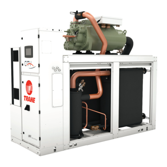
- Page 1 Water-cooled Liquid Chillers with Helical Rotary Compressors RTSF: 180-385kW (R1234ze) July 2020 RLC-SVX023B-GB Confi dential and proprietary Trane information Original instructions...
-
Page 2: Table Of Contents
Table of Contents Introduction ......................3 Unit model number description ............... 5 General Data ...................... 7 Unit Description ....................8 Installation - Mechanical ................. 10 Installation - Electrical ..................21 Operating Principles Mechanical ..............27 Typical Operating map ..................32 Controls/Tracer TD7 Operator Interface ............ -
Page 3: Introduction
These instructions are given as a guide to good practice in the installation, start-up, operation, and maintenance by the user, of Trane City chiller RTSF , manufactured in France. A separate manual is available for the use and maintenance of the unit’s control, Tracer™ UC800. They do not contain full service procedures necessary for the continued successful operation of this equipment. - Page 4 (PED) 97/23/EC or 2014/68/EU and Machinery Directive 2006/42/EC and for specifi c caution for R1234ze. Maintenance contract It is strongly recommended that you sign a maintenance contract with your local Trane Service Agency. This contract provides regular maintenance of your installation by a specialist in our equipment. Regular maintenance ensures that any malfunction is detected and corrected in good time and minimizes the possibility that serious damage will occur.
-
Page 5: Unit Model Number Description
Unit model number description Digit 1, 2, 3, 4 – Unit Model Digit 27 – Not Used RTSF Digit 28 – Evaporator pump Digit 5, 6, 7 – Unit size X = Without 50 = 50 Nominal tons 60 = 60 Nominal tons Digit 29 –... - Page 6 Unit model number description Digit 45 – Energy meter X = Without M = With Digit 46 – Condenser Pump Smart Flow Control/Other Condenser Pressure Control Outputs X = Without 1 = Condenser Pressure in % HPC 2 = Differential Pressure 3 = Condenser Head Pressure Flow Control 4 = VPF Constant Delta T Condenser Flow Control Digit 47 –...
-
Page 7: General Data
General Data Table 1 – General Data RTSF Standard effi ciency - R1234ze RTSF050 RTSF060 RTSF070 RTSF090 RTSF100 RTSF110 Indicative performances (1) Cooling Capacity (1) (kW) Total Power input in cooling (1) (kW) Unit Electrical data (2) (5) Low VI compressor - digit 20 =L Maximum Power Input (kW) Unit rated amps (2) -
Page 8: Unit Description
Unit Description Component location for typical RTSF Unit 2 = Power cable gland plate for customer wiring 4 = Suction line 5 = Oil separator 6 = Condenser water outlet 7 = Condenser water inlet 8 = Evaporator water outlet 9 = Evaporator water inlet 13 = External control wiring cable gland plate for... - Page 9 • For unit-mounted starters, cutouts are provided at the top of the panel for line-side wiring. • Supply and install the wire terminal lugs to the starter. • Supply and install fi eld wiring to the line-side lugs of the starter. Table 2 – Installation Responsibility Trane supplied Trane supplied Customer supplied Requirement...
-
Page 10: Installation - Mechanical
If the refrigerant pressure is below 3.4 bar at 21°C (2 bar at 10 °C), call a qualifi ed service organization and the appropriate Trane sales offi ce. NOTE: Pressure will be approximately 1.0 bar if shipped with the optional nitrogen charge. - Page 11 Installation - Mechanical Water Drainage Locate the unit near a large capacity drain for water vessel drain-down during shutdown or repair. Condenser and evaporator water pipes are provided with drain connections. Refer to “Water Piping. ” All local and national codes apply. Access Restrictions Refer to the unit submittals for specifi...
- Page 12 Installation - Mechanical Unit Leveling NOTE: The electrical panel side of the unit is designated as the “front” of the unit. Check unit level end-to-end by placing a level on the chiller structure (compressor frame for example). Adjust to within 5 mm of level front-to-back. Water Piping Piping Connections To prevent equipment damage, bypass the unit if using an acidic fl...
- Page 13 Installation - Mechanical Evaporator Piping Components Note: Make sure all piping components are between the shutoff valves, so that isolation can be accomplished on both the condenser and the evaporator. “Piping components” include all devices and controls used to provide proper water system operation and unit operating safety.
- Page 14 Installation - Mechanical Water Pressure Gauges and Thermometers Install fi eld-supplied thermometers and pressure gauges (with manifolds, whenever practical). Locate pressure gauges or taps in a straight run of pipe; avoid placement near elbows, etc. Be sure to install the gauges at the same elevation on each shell if the shells have opposite-end water connections.
- Page 15 Installation - Mechanical RTSF condensers Pressure drop on waterside RTSF condensers Pressure drop on waterside 1000 10.0 100.0 WaterFlow (L/s) RTSF evaporators Pressure drop on waterside RTSF evaporators Pressure drop on waterside 1000 10.0 100.0 WaterFlow (L/s) RLC-SVX023B-GB...
- Page 16 LERTC limit. • Maintain refrigerant charge at appropriate levels. If charge is in question, contact Trane service. A reduced or low level of charge can increase the likelihood of freezing conditions in the evaporator and/or LERTC diagnostic shutdowns.
- Page 17 Tables above should not be interpreted as suggesting operating ability or performance characteristics at all tabulated glycol percentages. Full unit simulation is required for proper prediction of unit performance for specifi c operating conditions. For information on specifi c conditions, contact Trane. RLC-SVX023B-GB...
- Page 18 2-way or 3-way valve as necessary to maintain chiller differential pressure. Methods other than those shown can be employed to achieve the same results. Contact your local Trane offi ce for details.
- Page 19 Installation - Mechanical Cooling device bypass – Figure 3 Cooling device bypass is also a valid control method if the chiller temperature requirements can be maintained. Advantage: • Excellent control by maintaining constant water fl ow through the condenser. Disadvantage: •...
- Page 20 Installation - Mechanical Condenser water pump with variable frequency drive – Figure 4 Advantages: • Pumping cost can be reduced. Good cooling device temperature control. • Relatively low fi rst cost. Disadvantage: • Increased rate of fouling due to lower water velocity in the condenser. Figure 4 1 = Electric valve actuator 2A = 3-way valve or 2 butterfl...
-
Page 21: Installation - Electrical
Frequency™ Drive) capacitors before servicing. Follow proper lockout/tagout procedures to ensure the power cannot be inadvertently energized. • For variable frequency drives or other energy storing components provided by Trane or others, refer to the appropriate manufacturer’s literature for allowable waiting periods for discharges capacitors. Verify with an appropriate voltmeter that all capacitors have discharged. - Page 22 Installation - Electrical Power Supply Wiring Model RTSF chillers are designed according to European standard EN 60204-1; therefore, all power supply wiring must be sized and selected accordingly by the project engineer. Water Pump Power Supply Provide power supply wiring with fused disconnect for both the chilled water and condenser water pumps. Electrical Panel Power Supply Power supply wiring instructions for the starter/control panel are: Run the line voltage wiring in conduit to the access opening(s) on the starter/control panel.
- Page 23 Installation - Electrical Interconnecting Wiring (Field Wiring Required) Important: Do not turn chiller on or off using the chilled water pump interlocks. When making fi eld connections, refer to the appropriate fi eld layout, wiring, schematics and controls diagrams that ship with the unit.
- Page 24 4 relays are available for this function as a Quad Relay Output LLID and a second quad relay board can be fi eld mounted if more than 4 different alarm/status are needed (refer to your local Trane service).
- Page 25 Installation - Electrical The Tracer UC800 Service Tool (TU) is used to install and assign any of the above listed events or status to each of the 4 relays. The default assignments for the 4 available relays are listed below. LLID Software LLID Name Relay Designation...
- Page 26 Installation - Electrical LonTalk Communication Interface - Optional Tracer UC800 provides an optional LonTalk Communication Interface (LCI-C) between the chiller and a BAS. An LCI-C LLID shall be used to provide “gateway” functionality between the LonTalk protocol and the chiller. Bacnet Communication Interface - Optional Tracer UC800 provides an optional Bacnet communication interface between the chiller and a BAS.
-
Page 27: Operating Principles Mechanical
• AFD (Adaptive Frequency Drive) Refrigeration (Cooling) Cycle The refrigeration cycle of the chiller is conceptually similar to that of other Trane chiller products. It makes use of a BPHE evaporator. The compressor is a twin-rotor helical-rotary type. It uses a suction gas-cooled motor that operates at lower motor temperatures under continuous full- and part-load operating conditions. - Page 28 Operating Principles Mechanical Cycle Description The refrigeration cycle for the chiller can be described using the pressure-enthalpy diagram shown in Figure 5. Key State Points are indicated on the fi gure and are referenced in the discussion following. Typical schematics of the system showing the refrigerant fl...
- Page 29 Operating Principles Mechanical Refrigerant fl ow diagram Refrigerant fl ow diagram for unit is supplied with drawing package with unit order. Figure 6 – Example of typical refrigerant fl ow diagram 1 = Screw compressor REFRIGERANT LINE OIL LINE 2 = Brazed plate evaporator CHILLED HEATED WATER LINE INSULATION 3 = Brazed plate condenser...
- Page 30 Operating Principles Mechanical Compressors The compressor used by the chiller consists of 3 distinct sections: the motor, the rotors and the bearing housing. Compressor Motor A two-pole, hermetic, squirrel-cage induction motor directly drives the compressor rotors. The motor is cooled by suction vapor drawn from the evaporator and entering the end of the motor housing through the suction line.
- Page 31 Operating Principles Mechanical Oil Management System Oil Separator The oil separator consists of a vertical tube, joined at the top by the refrigerant discharge line from the compressor. This causes the refrigerant to swirl in the tube and throws the oil to the outside, where it collects on the walls and fl...
-
Page 32: Typical Operating Map
Typical Operating map Figure 8 – Typical operating map AOC = Auxiliary Oil Cooler RLC-SVX023B-GB... -
Page 33: Controls/Tracer Td7 Operator Interface
The TD7 operator interface allows for daily operation tasks and setpoint changes. However to adequately service chiller, Tracer™ TU service tool is required (Non-Trane personnel, contact your local Trane offi ce for software purchase information). Tracer TU adds a level of sophistication that improves service technician effectiveness and minimizes chiller downtime. -
Page 34: Pre-Start Checkout
Trane assumes no responsibility for equipment failures which result from untreated or improperly treated water, or saline or brackish water. - Page 35 Pre-Start Checkout Unit Voltage Phasing It is important that proper rotation of the compressors be established before the unit is started. Proper motor rotation requires confi rmation of the electrical phase sequence of the power supply. The motor is internally connected for clockwise rotation with the incoming power supply phases A-B-C.
-
Page 36: Unit Start-Up
Unit Start-up Daily Unit Start Up The timeline for the sequence of operation begins with a power-up of the main power to the chiller. The sequence assumes 1 circuit RTSF water cooled chiller with no diagnostics or malfunctioning components. External events such as the operator placing the chiller in AUTO or STOP , chilled water fl... - Page 37 Unit Start-up System Restart after Extended Shutdown Verify that the oil line, service valve is open (back seated). Check the oil separator oil level (see Maintenance procedures section). Fill the evaporator and condenser water circuit. Vent the system while it is being fi lled. Open the vent on the top of the evaporator and condenser while fi...
-
Page 38: Periodic Maintenance
Periodic Maintenance Overview This section describes preventative maintenance procedures and intervals. Use a periodic maintenance program to ensure optimal performance and effi ciency of the units. An important aspect of the chiller maintenance program is the regular completion of the “Operating Log “ . When fi lled out properly the completed logs can be reviewed to identify any developing trends in the chiller’s operating conditions. - Page 39 Periodic Maintenance Annual Maintenance WARNING: Hazardous Voltage! Disconnect all electric power, including remote disconnects before servicing. Follow proper lockout / tagout procedures to ensure the power can not be inadvertently energized. Failure to disconnect power before servicing could result in death or serious injury. •...
- Page 40 Date____________________________________________________________________. * Return this completed checklist to your Trane Service offi ce as soon as possible to enable the start-up visit to be scheduled. Be aware that advance notifi cation is required to allow scheduling of the start-up as close to the requested date as possible.
-
Page 41: Maintenance Procedures
Use Table 6 to determine the acceptability of the oil. Trane approved oil is OIL0066E/OIL0067E. The proper charge amounts are given on General data. Note: Use an oil transfer pump to change the oil regardless of chiller pressure. - Page 42 Maintenance Procedures Oil Level Check Figure 9 – Determining oil level in the oil separator 1 = Oil separator 2 = Valve 3 = 1/4” refrigeration hose 4 = Sight glass 5 = Minimum oil level 6 = Maximum oil level How to measure the oil level: Use the oil drain valve (bottom side) and the service valve on the oil separator (top side).
- Page 43 Maintenance Procedures Removing Compressor Oil The oil in the compressor oil separator is under a constant positive pressure at ambient temperature. To remove oil, open the service valve located on the bottom of the oil separator and drain the oil into a suitable container using the procedure outlined below: CAUTION: POE Oil! Due to the hygroscopic properties of the POE oil, all oil must be stored in metal containers.
- Page 44 Maintenance Procedures Figure 10 – Oil Filter Replacement Chart Clean Filter Versus Recommended Filter Replacement GP2 / RTWD Clean Filter Versus Recommended Filter Replacement Line UC800 RTSF Pressure Protection Scheme Line CH530 RTWD Oil Pressure Protection Scheme Start protection line for 1st Start protection line for 1st 2.5 minutes of operation 2.5 minutes of operation...
- Page 45 Maintenance Procedures Refrigerant Charge If a low refrigerant charge is suspected, fi rst determine the cause of lost refrigerant. Once the problem is repaired follow the procedures below for evacuating and charging the unit. Refrigerant recovery Insure that the water fl ow is maintained on condenser and evaporator during all the recovery operation. Connections on evaporator and condenser are available to remove the refrigerant.
-
Page 46: Recommended Service Routine Frequencies
As a commitment to our customers, we have created a wide service network staffed with experienced factory- authorized technicians. At Trane we offer all the benefi ts of after sales service direct from the manufacturer and we are committed to our mission statement to provide effi cient customer care. -
Page 47: Additional Services
Vibration analysis is required when oil analysis reveals the presence of wear indicating the start of possible bearing or motor failure. Trane oil analysis has the ability to identify the type of metallic particles in the oil which, when combined with the vibration analysis, will clearly point out the failing components. - Page 48 For more information, please visit trane.com or tranetechnologies.com. Trane has a policy of continuous product and product data improvement and reserves the right to change design and specifi cations without notice. We are committed to using environmentally conscious print practices.
Need help?
Do you have a question about the CITY RTSF Series and is the answer not in the manual?
Questions and answers