Table of Contents
Advertisement
Installation, Operation, and Maintenance
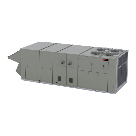
Voyager™ 3
Packaged Rooftop Air Conditioners with Symbio™
700 Controls
27.5 to 50 Tons - 60 Hz
22.9 to 41.7 Tons (82-142 kW) - 50 Hz
"C" and later design
sequence
60Hz/3 phase: TC*,
TE*, YC*, 330C, 360C,
420C, 480C, 600C
50 Hz/3 phase: TC*,
TE*, YC*, 275C, 305C,
350C, 400C, 500C
Only qualified personnel should install and service the equipment. The installation, starting up, and servicing of heating, ventilating, and air-conditioning equipment
can be hazardous and requires specific knowledge and training. Improperly installed, adjusted or altered equipment by an unqualified person could result in death or
serious injury. When working on the equipment, observe all precautions in the literature and on the tags, stickers, and labels that are attached to the equipment.
November 2022
SAFETY WARNING
RT-SVX34V-EN
Advertisement
Table of Contents

Subscribe to Our Youtube Channel
Related Manuals for Trane Technologies Voyager 3


Summary of Contents for Trane Technologies Voyager 3
- Page 1 Installation, Operation, and Maintenance Voyager™ 3 Packaged Rooftop Air Conditioners with Symbio™ 700 Controls 27.5 to 50 Tons - 60 Hz 22.9 to 41.7 Tons (82-142 kW) - 50 Hz “C” and later design sequence 60Hz/3 phase: TC*, TE*, YC*, 330C, 360C, 420C, 480C, 600C 50 Hz/3 phase: TC*, TE*, YC*, 275C, 305C,...
- Page 2 Introduction Read this manual thoroughly before operating or servicing WARNING this unit. Proper Field Wiring and Grounding Required! Warnings, Cautions, and Notices Failure to follow code could result in death or serious Safety advisories appear throughout this manual as injury. required.
- Page 3 Phone: 855-803-3563 This document describes the proper installation, startup, Email: traneuniversity@trane.com operation, and maintenance procedures for Voyager 3 units. Revision History By carefully reviewing the information within this manual and following the instructions, the risk of improper Updated to include Symbio™...
- Page 4 Table of Contents Model Number Description ....6 Set 1. Cooling Only Rooftop Units and Cooling with Gas Heat Rooftop 60 Hz Description......6 Units .
-
Page 5: Table Of Contents
Table of Contents Installation Piping......33 For Single Zone Variable Air Volume Units ....... . 71 General Requirements . - Page 6 Model Number Description 60 Hz Description Digit 1, 2 — Unit Function Digit 10 — Design Sequence Digit 15 — Outside Air Selection TC = DX Cooling, No Heat A = First A = No Outside Air TE = DX Cooling, Electric Heat B = 0-25% Manual Damper YC = DX Cooling, Natural Gas Heat C = 0-100% Economizer, Dry Bulb Control...
- Page 7 Model Number Description Digit 27 Miscellaneous Options Elec. Heater Tons 0 = 5kA SCCR Digit 17 Rated D = High Fault 65kA SCCR Disconnect Volt. E = High Fault 65kA SCCR Disconnect w/Powered 0 = No Service Valves Convenience Outlet A = Service Valves Digit 28 27.5...
- Page 8 Model Number Description 50 Hz Description Digit 1, 2 — Unit Function Digit 11 — Exhaust Digit 15 — Outside Air Selection TC = DX Cooling, No Heat 0 = None A = No Outside Air TE = DX Cooling, Electric Heat 1 = Barometric Relief (Available w/ Economizer B = 0-25% Manual Damper only)
- Page 9 Model Number Description Miscellaneous Options Digit 29 — Efficiency/ Condenser Coil Options 0 = Standard Efficiency (eStage) Unit Digit 17 J = Standard Efficiency (eStage) Unit with Corrosion Protected Condenser Coil 0 = No Service Valves K = High Efficiency Unit (eStage) A = Service Valves L = High Efficiency Unit (eStage) with Corrosion Discharge service valves are standard and...
- Page 10 General Information About the Unit WARNING No Step Surface! Overall unit dimensional data is illustrated in “Unit Dimensions and Weights,” p. 11. Each package rooftop Failure to follow instruction below could result in unit ships fully assembled and charged with the proper death or serious injury.
- Page 11 Recommended Clearances Ductwork installation recommendations are included in the instruction booklet that ships with each Trane accessory Adequate clearance around and above each Voyager 3 roof curb kit. unit is required to ensure proper operation and to allow Note: For sound consideration, cut only the holes in the sufficient access for servicing.
- Page 12 Unit Dimensions and Weights Unit Dimensions Figure 1. 60 Hz 27.5-35, 50 Hz 23-29 Tons (TCD, TED, YCD low heat) Figure 2. Rear view showing duct openings for horizontal supply and return, 60 Hz 27.5-35, 50Hz 23-29 Tons (TCH, TEH, YCH low heat) 1 1/4 3 1/4 (32)
- Page 13 Unit Dimensions and Weights Figure 3. 60 Hz 27.5-35, 50 Hz 23-29 tons (TC, TE, YC low heat) NOTES: 1. SEE DETAIL HOOD DRAWING FOR HORIZONTAL / DOWNFLOW UNITS FOR ADDITIONAL DIMENSION AND LOCATION. 90 3/8" 2295.5mm 180 5/16" 4579.9mm SEE NOTE 2 3.25 [82.55mm] TO TOP OF FAN GRILLE 70 7/16"...
- Page 14 Unit Dimensions and Weights Figure 5. 60 Hz 27.5-35 tons (YCD high heat) 4991 Figure 6. Rear view showing duct openings for horizontal supply and return, 60 Hz 27.5-35 Tons (YCH high heat) 1 1/4 3 1/4 (32) (81) Notes: •...
- Page 15 Unit Dimensions and Weights Figure 7. 60 Hz 27.5-35 tons (YC high heat) 90 5/8" NOTES: 2301.8mm 1. SEE ROOFCURB DRAWING FOR DETAILS ON FIELD DUCT FITUP AND CONNECTIONS 2. SEE DETAIL HOOD DRAWING FOR HORIZONTAL / DOWNFLOW UNITS FOR ADDITIONAL DIMENSION 208 1/16"...
- Page 16 Unit Dimensions and Weights Figure 9. 60 Hz 40-50, 50 Hz 33-42 tons (TCD, TED, YCD low and high heat) Figure 10. Rear view showing duct openings for horizontal supply and return, 60 Hz 40-50, 50Hz 33-42 Tons (TCH, TEH, YCH low and high heat) 1 1/4 3 1/4 (32)
- Page 17 Unit Dimensions and Weights Figure 11. 60 Hz 40-50, 50 Hz 33-42 tons (TC, TE, YC low and high heat) NOTES: 90 5/8" 1. SEE ROOFCURB DRAWING FOR DETAILS 2301.8mm ON FIELD DUCT FITUP AND CONNECTIONS 2. SEE DETAIL HOOD DRAWING FOR HORIZONTAL / DOWNFLOW UNITS FOR ADDITIONAL DIMENSION AND LOCATION.
- Page 18 Unit Dimensions and Weights Figure 13. Side view showing fresh air and power Figure 15. Location of “Ship With” items for TC*, TE*, exhaust hoods for downflow return and YC* units VFD ACCESS Fresh Air Hood CONTROL PANEL Pow er COMPRESSOR ACCESS Exhaust End of...
- Page 19 Unit Dimensions and Weights Table 1. Minimum operating clearances installation (horizontal, downflow, and mixed airflow configurations) Var. Freq. Drives Non- Factory (VFD’s) 0-25% Thru-the Roof Curb Unit Model Baro. Power Serv. Fused GFI with HGRH Econ. base With (60Hz/50Hz) Relief Exhaust Valves Discon.
- Page 20 Unit Dimensions and Weights Table 3. Center of gravity (continued) Center-of-Gravity (inches) YC High YC Low Unit (60Hz) 40 Tons 114.6 41.2 114.7 41.3 114.3 41.9 115.4 40.6 50 Tons 114.1 40.8 114.3 40.9 114.0 41.5 115.0 40.2 Notes: Center-of-gravities shown are for standard efficiency units and include the following features: 10HP supply fan motor, supply fan VFD, 100% economizer, 2" MERV 8 filters, SZVAV system control, GFCI, no exhaust, and hail guards.
- Page 21 Unit Dimensions and Weights Table 5. Approximate unit operating weight Approximate Unit Operating Weight (lb) Unit (60Hz) YC High YC Low 27.5 Tons 4183 4303 4468 4651 30 Tons 4195 4315 4480 4663 35 Tons 4226 4346 4511 4694 40 Tons 4821 5044 5130...
- Page 22 Pre-Installation Electrical Requirements The checklist listed below is a summary of the steps required to successfully install a Voyager 3 rooftop unit. WARNING This checklist is intended to acquaint the installing personnel with what is required in the installation process.
- Page 23 Installation General Requirements Condensate Drain Connection Figure 19. Condensate overflow switch location Each commercial rooftop unit is equipped with one (1) 1-1/ 4 inch Female NPT (threaded) drain connection. Refer to “Unit Dimensions and Weights,” p. 11 for the location of the connector. A condensate trap must be installed due to the drain connection being on the “negative pressure”...
- Page 24 Installation General Requirements Units with Statitrac™ space pressurization control to the fitting indicated in the illustration. 1. Open the filter access door, and locate the Statitrac 2. Route the opposite end of the tubing to a suitable Transducer Assembly illustrated in Figure 21, p.
- Page 25 Installation General Requirements Figure 21. Transducer assembly Static reference tubing connects here (O/A sensor) Space pressure sensing tubing connects here Space pressure calibration solenoid Statitrac Tube from low side of velocity flow ring Tube from high side of velocity flow ring Traq Solenoid Transducer...
- Page 26 Installation Electrical WARNING An overall layout of the field required power wiring is illustrated in . To insure that the unit supply power wiring is Hazardous Voltage! properly sized and installed, follow the guidelines outlined Failure to disconnect power before servicing could below.
- Page 27 Installation Electrical latest edition). Refer to DSS calculations “Electrical Note: When the factory installed through-the-base Wire Sizing and Protection Device Equations,” p. 28 option is not used, the installing contractor is determining correct size. required to seal any holes made in the base of the unit to prevent water from leaking into the Location for the electrical service entrance is shown building.
- Page 28 Installation Electrical Through-the-Base Electrical Keep in mind when determining LOADS that crankcase heaters are disabled in the cooling mode. (Optional Accessory) DSS = 1.15 x (LOAD1 + LOAD2 + LOAD4) Liquid-tight conduit couplings are secured to the base of Select a disconnect switch size equal to or larger than the the unit for both power and control wiring.
- Page 29 Installation Electrical Low Voltage Wiring WARNING Proper Field Wiring and Grounding An overall layout of the various control options available is illustrated in . The required number of conductors for each Required! control device are listed in the illustration. Failure to follow code could result in death or serious A typical field connection diagram for the sensors and other injury.
- Page 30 Installation Electrical Table 9. AC conductors size • Do not run the electrical wires transporting DC signals in or around conduit housing high voltage wires. Distance from unit to control Recommended wire size Table 10. DC conductors 18 gauge 000-460 feet Distance from unit to control Recommended wire size 16 gauge...
- Page 31 Evaporator Frost Control Shielded Twisted Pair (Belden 8760 or equivalent). Refer to the specific Remote Panel for wiring details. Frostat is standard on all Voyager 3 27.5 to 50 ton units. Thermostat Discharge Line Temp Switch The unit must have a thermostat to operate.
- Page 32 Installation Electrical temp) in case of indoor fan failure (cooling) or outdoor fan • The red light indicates that unit operation has been failure (heating). prevented. There are two conditions that will prevent unit operation: Phase Monitor – The power supply circuit is not balanced with the proper phase sequence of L1, L2, L3 for the 3 This sensor monitors voltage between the 3 conductors of conductors of a 3 phase circuit.
-
Page 33: Installation Piping
Installation Piping General Requirements 5. Install a pressure regulator at the unit that is adequate to maintain 7" w.c. for natural gas and 11" w.c. for LP WARNING gas while the unit is operating in the "High Heat" mode. Hazardous Gases and Flammable 6. - Page 34 Installation Piping Table 12. Sizing natural gas pipe mains and branches Gas Input (Cubic Feet/Hour) Gas Supply Pipe Run (ft) 1-1/4” Pipe 1-1/2” Pipe 2" Pipe 2-1/2” Pipe 3"Pipe 4"Pipe 1050 1600 3050 4800 8500 17500 1100 2100 3300 5900 12000 1650 2700...
- Page 35 Installation Piping Figure 26. 600MBh 2–stage gas train Figure 28. 400MBh 2–stage gas train Figure 27. 600MBh Mod gas train Figure 29. 400MBh Mod gas train Figure 30. 800MBh 2–stage gas train RT-SVX34V-EN...
- Page 36 Installation Piping Figure 31. 800MBh Mod gas train RT-SVX34V-EN...
-
Page 37: Startup
Service Test State is interpreted based on the equipment’s through the controller user interfaces, including the Symbio configuration, see BAS-APG048*-EN, Symbio 700 for Service and Installation mobile application. Voyager 3 Packaged Rooftop Air-Conditioners Application Guide. Figure 32. Symbio 700 service test mode Sequence of Operation closes to 15% position and that the supply temperature rises 10ºF more than when in cooling mode stage 2. -
Page 38: Preparing The Unit For Operation
Startup • Verify that the Remote panel “System” selection switch, • Optional Service Valves - Verify that the discharge “Fan” selection switch, and “Zone Temperature” service valve and suction service valve fully open on settings for automatic operation are correct. each circuit. -
Page 39: Voltage Supply And Voltage
Startup WARNING • VD (reading farthest from average) = 221 • The percentage of imbalance equals: [(226–221) / 226] Live Electrical Components! x 100 = 2.2% Failure to follow all electrical safety precautions when The 2.2% imbalance in this example exceeds the exposed to live electrical components could result in maximum allowable imbalance of 2.0%. - Page 40 Startup RT-SVX34V-EN...
- Page 41 Startup RT-SVX34V-EN...
-
Page 42: Verifying Proper Fan Rotation
Startup Verifying Proper Fan Rotation Confirm that brown, orange, and yellow wire are on L1, L2, L3 for the supply fan power harnesses. Make necessary WARNING interchange if they are not. Rotating Components! Note: Interchanging “Load” side power wires at the supply fan contactor will only affect the Fan Rotation. - Page 43 Startup Figure 33. Supply fan performance—27.5 -35 ton—60 Hz Figure 34. Supply fan performance — 40 and 50 ton—60 Hz RT-SVX34V-EN...
- Page 44 Startup Figure 35. Supply fan performance – 22.9-29.1 tons Supply Fan Performance (996) (872) (747) (623) (498) (374) (249) (125) (0.0) 2000 4000 6000 8000 10000 12000 14000 16000 18000 20000 22000 24000 26000 Volumetric Airflow Rate(CFM) (.94) (1.89) (2.83) (3.78) (4.72) (5.66)
- Page 45 Startup Table 15. Supply air fan drive selections—60 Hz 7.5 HP 10 HP 15 HP 20 HP 25 HP Nominal Tons Drive No. Drive No. Drive No. Drive No. Drive No. 27.5 RT-SVX34V-EN...
- Page 46 Startup Table 16. Component static pressure drops (in. W.G.) — 60Hz Heating System Filters High Standard Efficiency ID Efficiency ID Throw- MERV 14 Hot Gas MERV 8 High Eff Gas Heat Electric Heat Coil Coil Nom. CFM Std Econo- away High Eff Reheat Tons...
- Page 47 Startup Table 17. Component static pressure drops in. W.G (I-P) — 50Hz (continued) Heating System Filters High Standard Efficiency ID Efficiency ID Throw- MERV 14 Hot Gas MERV 8 High Eff Gas Heat Electric Heat Coil Coil Nom. CFM Std Econo- away High Eff...
-
Page 48: Exhaust Fan Operation
Startup Table 18. Supply air fan drive selections—50 Hz (continued) 7.5 HP (5.6 kW) 10 HP (7.5 kW) 15 HP (10 kW) 20 HP (15 kW) Nominal Tons (kW) Drive No. Drive No. Drive No. Drive No. 33 (108) 42 (146) Exhaust Fan Operation damper blades. - Page 49 Startup Table 19. Power exhaust fan performance—27.5-35 ton—60 Hz Power Exhaust Selection 100% Damper Open Position Return Duct Static (in. 3812 6866 7624 13742 3497 5296 6995 10591 3190 4458 6325 9000 2884 3812 5768 7635 2621 3359 5241 6719 2342 2885 4683...
- Page 50 Startup Table 21. Power exhaust fan performance—22.9-29.2 tons—50 Hz (continued) Power Exhaust Selection 100% Damper Open Position Return Duct Static (Pa) 99.6 1031 1321 2061 2643 124.5 1135 1842 2270 Table 22. Power exhaust fan performance—33.3-41.7 tons—50 Hz Power Exhaust Selection 100% Damper Open Position Return Duct Static (Pa)
-
Page 51: Economizer Damper Adjustment
Startup Figure 39. (Upflow) Exhaust maximum damper pressures and over pressurization of the space when the position unit is operating in the “economizer” mode. The purpose of adjusting the amount of O/A damper travel is to maintain a balance or equal pressure between the O/A dampers and the pressure drop of the return air More Exhaust system. - Page 52 Startup Table 23. 27.5 - 35 Ton downflow economizer (O/A) damper static pressure setup (continued) Return Air Duct Static + Return Air Damper Static (Inches of Water) System Design CFM Drive Rod Position 12000 12500 13000 13500 14000 14500 15000 Table 24.
- Page 53 Startup Table 25. 40 - 50 Ton downflow economizer (O/A) damper static pressure setup (continued) Return Air Duct Static + Return Air Damper Static (Inches of Water) System Design CFM Drive Rod Position 15000 15500 16000 16500 17000 17500 18000 18500 19000 19500...
-
Page 54: Economizers
Startup Table 26. 40 - 50 Ton horizontal economizer (O/A) damper static pressure setup (continued) Return Air Duct Static + Return Air Damper Static (Inches of Water) System Design CFM Drive Rod Position 21000 21500 22000 Models with Ultra-Low Leak Economizers Figure 42. - Page 55 Startup Figure 44. Actuator for OA damper - horizontal Figure 45. Actuator auto-scaling feature details Control Reversing Switch Must Be Set to Match Spring Return Direction Table 27. 27.5 - 35 Ton downflow economizer (O/A) - ultra-low leak economizer Return Air Duct Static + Return Air Damper Static (Inches of Water) System Design CFM Stroke limit setting % on OA damper actuator...
- Page 56 Startup Table 28. 27.5 - 35 Ton horizontal economizer (O/A) - ultra-low-leak economizer (continued) Return Air Duct Static + Return Air Damper Static (Inches of Water) System Design CFM Stroke limit setting % on OA damper actuator 9500 10000 11000 11500 12000 12500...
- Page 57 Startup Table 30. 40 - 50 Ton horizontal economizer (O/A) - ultra-low-leak economizer Return Air Duct Static + Return Air Damper Static (Inches of Water) System Design CFM Stroke limit setting % on OA damper actuator 12000 12500 13000 13500 14000 14500 15000...
-
Page 58: Manual Outside Air Damper
Startup Manual Outside Air Damper HTB1 OR UNIT DISCONNECT SWITCH. 3. Remove the mist eliminator retainer bracket and the Units ordered with the 25% manual outside air option have mist eliminators from the fresh air hood. two slidable dampers. By adjusting one or both, the desired amount of fresh air entering the system can be obtained. -
Page 59: Starting 27.5-50 Tons Standard And High Efficiency Units
Startup Starting 27.5-50 Tons Standard and High Compressor Oil Efficiency Units Once all of the compressors have been started, verify that the oil level is visible through the sight glass or above the Install a set of service gauges onto the suction and sight glass. - Page 60 Startup Figure 47. 27.5 Ton operating pressure — standard efficiency (60Hz) COOLING CYCLE PRESSURE CURVE 118 F OD Ambient 105 F OD Ambient 95 F OD Ambient 85 F OD Ambient 75 F OD Ambient 55 F OD Ambient 65 F OD Ambient Suction Pressure (Psig) Figure 48.
- Page 61 Startup Figure 49. 35 Ton operating pressure — standard efficiency (60 Hz) COOLING CYCLE PRESSURE CURVE 118 F OD Ambient 105 F OD Ambient 95 F OD Ambient 85 F OD Ambient 75 F OD Ambient 55 F OD Ambient 65 F OD Ambient Suction Pressure (Psig) Figure 50.
- Page 62 Startup Figure 51. 50 Ton operating pressure —standard efficiency (60Hz) COOLING CYCLE PRESSURE CURVE 118 F OD Ambient 105 F OD Ambient 95 F OD Ambient 55 F OD Ambient 85 F OD Ambient 75 F OD Ambient 65 F OD Ambient Suction Pressure (Psig) Figure 52.
- Page 63 Startup Figure 53. 30 Ton operating pressure — high efficiency (60 Hz) COOLING CYCLE PRESSURE CURVE 118 F OD Ambient 105 F OD Ambient 95 F OD Ambient 85 F OD Ambient 75 F OD Ambient 55 F OD Ambient 65 F OD Ambient Suction Pressure (Psig) Figure 54.
- Page 64 Startup Figure 55. 40 Ton operating pressure — high efficiency (60 Hz) COOLING CYCLE PRESSURE CURVE 118 F OD Ambient 105 F OD Ambient 95 F OD Ambient 85 F OD Ambient 55 F OD Ambient 75 F OD Ambient 65 F OD Ambient Suction Pressure (Psig) Figure 56.
- Page 65 Startup Figure 57. 22.9 Ton operating pressure — standard efficiency (50 Hz) COOLING CYCLE PRESSURE CURVE 118 F OD Ambient 105 F OD Ambient 95 F OD Ambient 85 F OD Ambient 75 F OD Ambient 55 F OD Ambient 65 F OD Ambient Suction Pressure (Psig) Figure 58.
- Page 66 Startup Figure 59. 29.2 Ton operating pressures — standard efficiency (50 Hz) COOLING CYCLE PRESSURE CURVE 118 F OD Ambient 105 F OD Ambient 95 F OD Ambient 85 F OD Ambient 75 F OD Ambient 55 F OD Ambient 65 F OD Ambient Suction Pressure (Psig) Figure 60.
- Page 67 Startup Figure 61. 41.7 Ton operating pressure— standard efficiency (50 Hz) COOLING CYCLE PRESSURE CURVE 118 F OD Ambient 105 F OD Ambient 95 F OD Ambient 55 F OD Ambient 85 F OD Ambient 75 F OD Ambient 65 F OD Ambient Suction Pressure (Psig) Figure 62.
- Page 68 Startup Figure 63. 25.4 Ton operating pressure — high efficiency (50 Hz) COOLING CYCLE PRESSURE CURVE 118 F OD Ambient 105 F OD Ambient 95 F OD Ambient 85 F OD Ambient 75 F OD Ambient 55 F OD Ambient 65 F OD Ambient Suction Pressure (Psig) Figure 64.
-
Page 69: Noises
Startup Figure 65. 33.3 Ton operating pressure — high efficiency (50 Hz) COOLING CYCLE PRESSURE CURVE 118 F OD Ambient 105 F OD Ambient 95 F OD Ambient 85 F OD Ambient 55 F OD Ambient 75 F OD Ambient 65 F OD Ambient Suction Pressure (Psig) Figure 66. -
Page 70: Compressor Crankcase Heaters
8 hours before starting the unit. Follow the Service Test instructions in the Symbio 700 Charging by Subcooling Controller with Voyager 3 Packaged Rooftop Air Conditioners literature (ACC-APG002A-EN) to put the unit The unit is shipped with a complete refrigerant charge. -
Page 71: Electric Heat Units
Startup Once the ignition system and ignitors have been checked, Note: When firing a modulating unit for the first time, a open the main power disconnect switch to reset the “humming”, or resonance sound may be heard. This Symbio™ 700 controls. is an operational sound made by the burner screen as it burns in. - Page 72 Startup The Symbio™ 700 controls have input setpoint – DA Cool - Fan SPD - _____Setpoint potentiometers inside the control panel that are set at the – EXH Fan - _____Setpoint factory which will allow the unit to operate and maintain •...
-
Page 73: Sequence Of Operation
Sequence of Operation See Symbio™ 700 Controller with Voyager 3 Packaged Rooftop Air-Conditioners Application Guide (BAS- APG048*-EN). RT-SVX34V-EN... -
Page 74: Maintenance
Maintenance Fan Belt Adjustment 1. To determine the appropriate belt deflection: a. Measure the center-to-center distance, in inches, The supply fan belts must be inspected periodically to between the fan sheave and the motor sheave. assure proper unit operation. b. Divide the distance measured in Step 1a by 64; the Replacement is necessary if the belts appear frayed or resulting value represents the amount of belt worn. - Page 75 Maintenance Table 33. Belt tension measurements and deflection forces Deflection Force (Lbs.) Belts Small P.D 358 Gripnotch Cross Super Gripbelts Gripnotch Steel Cable Gripbelts 358 Gripbelts Range Belts Section Min. Max. Min. Max. Min. Max. Min. Max. Min. Max. 3.0 -3.6 4 1/2 3 7/8 5 1/2...
- Page 76 Maintenance Table 34. Supply fan sheave and belt (continued) Fan Bushing Motor Bushing Fan Sheave (a) (b) (c) Motor Sheave Tons Motor Belt Brown- Brown- Browning Browning BX95 2B5V124 2B124SK B 1 11/16 SK 1 11/16 2BK36H 2BK36H H 1-3/8 H-1-3/8 Notched BX95...
-
Page 77: Monthly Maintenance
Maintenance Monthly Maintenance ☐ Inspect the fresh air and return air damper hinges and pins to ensure that all moving parts are securely WARNING mounted. Keep the blades clean as necessary. Hazardous Voltage w/Capacitors! WARNING Failure to disconnect power and discharge capacitors Rotating Components! before servicing could result in death or serious Failure to disconnect power before servicing... -
Page 78: Heating Season
Maintenance ☐ Make sure that all retaining screws are reinstalled in the ☐ After greasing the bearings, check the setscrews to unit access panels once these checks are complete. ensure that the shaft is held securely. Make sure that all bearing braces are tight. -
Page 79: Refrigerant Coils
Maintenance • Fan brake horsepower Note: Before attempting to enter the unit, bridge between the main supports. Bridging may • Static pressure losses consist of multiple 2 by 12 boards or sheet At least once each year—or more often if the unit is located metal grating. -
Page 80: Fall Restraint
Maintenance Table 37. Sample maintenance log Refrigerant Circuit #1 Current Date Ambient Temp Suct. Press. Disch. Press Liquid Press Compr. Oil Super- heat F/ Sub-cool F/C Psig/kPa Psig/kPa Psig/kPa Level - ok - low - ok - low - ok - low - ok - low... -
Page 81: Refrigeration System
Maintenance Refrigeration System Important: Do Not release refrigerant to the atmosphere! If adding or removing refrigerant is required, the WARNING service technician must comply with all federal, state, and local laws. R-410A Refrigerant under Higher • To prevent cross contamination of Pressure than R-22! refrigerants and oils, use only dedicated R- Failure to use proper equipment or components as... -
Page 82: Compressor Replacements
Maintenance Note: Refrigerant oil is detrimental to some roofing Figure 69. Precision suction restrictor materials. Care must be taken to protect the roof from oil leaks or spills. Charge the new oil into the Schrader valve on the shell of the compressor. - Page 83 Maintenance menu does not display) c. Select Initialization 2. Scroll down to Load & Motor, press OK d. Press OK 3. Select 1-2, press OK e. Cut off the mains supply and wait until the display turns off. 4. Press down until parameter 1-23 is displayed. Parameter 1-23 can then be modified by pressing OK Reconnect the mains supply - the frequency and pressing the Up and Down buttons.
- Page 84 Maintenance Table 39. Relief/return fan VFD parameters Menu Name Unit Language English US 0-01 Regional Settings 0-03 North America Set to applicable unit power supply 200-240V/60Hz for 200 & 230V/60Hz units; 440-480V/60Hz for 460V/60Hz units; 525-600V/60Hz for 575V/60Hz units; 380-440V/50Hz for 380 & 0-06 (TR150 only) Grid Type 415V/50Hz supply.For IT Grid (no...
- Page 85 Maintenance Table 39. Relief/return fan VFD parameters (continued) Menu Name Unit Terminal 53 Low Ref./Feedb. 6-14 Value Analog In/Out Terminal 53 High Ref./Feedb. 6-15 Value 8.0 kHz (drive dependant, set to Switching Frequency 14-01 5kHz if 8kHz not available) 391V for 460V 60Hz unit, leave at 14-11 (TR200 only) Mains Voltage at Mains Fault default otherwise...
-
Page 86: Diagnostics
Diagnostics For diagnostic information, see Symbio™ 700 Controller Application Guide (BAS-APG048*-EN). with Voyager 3 Packaged Rooftop Air-Conditioners RT-SVX34V-EN... -
Page 87: Troubleshooting
Recommended Action 1. No power to the Unit. 1. Check line voltage at service disconnect. 2. See Symbio™ 700 Controller with Voyager 3 Packaged 2. No power to the Symbio™ 700. Rooftop Air Conditioners (BAS-APG048*-EN) for Symbio 700 troubleshooting details. - Page 88 3. Check ODM, replace if necessary. 3. ODM3 and/or 4 has failed. G. ODM 3 and/or 4 will not cycle. 4. See Symbio™ 700 Controller with Voyager 3 Packaged 4. Symbio™ 700 or Adapter Board is defective. Rooftop Air Conditioners (BAS-APG048*-EN) for Symbio 700 troubleshooting details.
- Page 89 R. Power Exhaust will not operate. necessary 3. Perform the ECA Test Procedures discussed previously. 3. ECA has failed. 1. See Symbio™ 700 Controller with Voyager 3 Packaged 1. Symbio™ 700 has Failed Rooftop Air Conditioners (BAS-APG048*-EN) for Symbio S. VFD will not operate properly 700 troubleshooting details.
-
Page 90: Unit Wiring Diagram Numbers
Unit Wiring Diagram Numbers Diagram Schematic Type Voltage Description Number Sheet 1; Power 12134517 All Units w/o Supply Fan Bypass 12134518 Sheet 2; Power w/ Supply Fan Bypass 12134519 Sheet 3; Symbio 700 12134528 All Units Sheet 4; Adapter Board 12134529 All Units w/o Supply Fan Bypass... -
Page 91: Warranty And Liability Clause
Warranty and Liability Clause COMMERCIAL EQUIPMENT - 20 The warranty and liability set forth herein are in lieu of all other warranties and liabilities, whether in contract or in TONS AND LARGER AND negligence, express or implied, in law or in fact, including RELATED ACCESSORIES implied warranties of merchantability and fitness for particular use. - Page 92 Trane - by Trane Technologies (NYSE: TT), a global innovator - creates comfortable, energy efficient indoor environments for commercial and residential applications. For more information, please visit trane. com or tranetechnologies.com. Trane has a policy of continuous product and product data improvements and reserves the right to change design and specifications without notice. We are committed to using environmentally conscious print practices.
Need help?
Do you have a question about the Voyager 3 and is the answer not in the manual?
Questions and answers