Table of Contents
Advertisement
Installation, Operation, and Maintenance
VariTrane™ ™ Variable Air Volume
(VAV) Terminal Air Units
Shutoff, Fan Powered, and CoolSense™
Sensible Cooling
S S i i n n g g l l e e - - D D u u c c t t : : VCCF, VCEF, VCWF
D D u u a a l l - - D D u u c c t t : : VDDF
F F a a n n - - P P o o w w e e r r e e d d : : VPCF, VPEF, VPWF, VSCF, VSEF, VSWF
F F a a n n - - P P o o w w e e r r e e d d L L o o w w H H e e i i g g h h t t : : LPCF, LPEF, LPWF, LSCF, LSEF, LSWF
C C h h i i l l l l e e d d W W a a t t e e r r S S e e n n s s i i b b l l e e C C o o o o l l i i n n g g T T e e r r m m i i n n a a l l U U n n i i t t s s : : LDCF, LDEF, LDWF
Only qualified personnel should install and service the equipment. The installation, starting up, and servicing of heating, ventilating, and air-conditioning
equipment can be hazardous and requires specific knowledge and training. Improperly installed, adjusted or altered equipment by an unqualified person
could result in death or serious injury. When working on the equipment, observe all precautions in the literature and on the tags, stickers, and labels that
are attached to the equipment.
March 2022
S S A A F F E E T T Y Y W W A A R R N N I I N N G G
V V A A V V - - S S V V X X 0 0 8 8 U U - - E E N N
Advertisement
Table of Contents

Subscribe to Our Youtube Channel
Related Manuals for Trane Technologies VariTrane VCCF


Summary of Contents for Trane Technologies VariTrane VCCF
- Page 1 Installation, Operation, and Maintenance VariTrane™ ™ Variable Air Volume (VAV) Terminal Air Units Shutoff, Fan Powered, and CoolSense™ Sensible Cooling S S i i n n g g l l e e - - D D u u c c t t : : VCCF, VCEF, VCWF D D u u a a l l - - D D u u c c t t : : VDDF F F a a n n - - P P o o w w e e r r e e d d : : VPCF, VPEF, VPWF, VSCF, VSEF, VSWF F F a a n n - - P P o o w w e e r r e e d d L L o o w w H H e e i i g g h h t t : : LPCF, LPEF, LPWF, LSCF, LSEF, LSWF...
- Page 2 Introduction Read this manual thoroughly before operating or W W A A R R N N I I N N G G servicing this unit. P P r r o o p p e e r r F F i i e e l l d d W W i i r r i i n n g g a a n n d d G G r r o o u u n n d d i i n n g g R R e e q q u u i i r r e e d d ! ! Warnings, Cautions, and Notices F F a a i i l l u u r r e e t t o o f f o o l l l l o o w w c c o o d d e e c c o o u u l l d d r r e e s s u u l l t t i i n n d d e e a a t t h h o o r r...
- Page 3 I I n n t t r r o o d d u u c c t t i i o o n n About This Manual W W A A R R N N I I N N G G F F o o l l l l o o w w E E H H S S P P o o l l i i c c i i e e s s ! ! This manual describes the installation of with recommended wiring, piping, and mounting of single-...
- Page 4 I I n n t t r r o o d d u u c c t t i i o o n n company immediately of any short ship or damaged and to make changes to its content without obligation equipment.
-
Page 5: Table Of Contents
Table of Contents Model Numbers ......6 Chilled Water Sensible Cooling Terminal Units Moisture Sensor Installation ..27 Single-Duct VAV Units . -
Page 6: Model Numbers
Model Numbers Single-Duct VAV Units Digit 1, 2— Unit Type Digit 12, 13, 14, 15 — Controls Digit 12, 13, 14, 15 — Controls (continued) (continued) VC = VariTrane™ Single—Duct DD22 = VV550 DDC- Vent Flow control to DD56 = UC400 Basic plus - Local (Water heat operate prop water valve - N.O. - Page 7 M M o o d d e e l l N N u u m m b b e e r r s s Digit 12, 13, 14, 15 — Controls Digit 12, 13, 14, 15 — Controls Digit 12, 13, 14, 15 — Controls (continued) (continued) (continued)
- Page 8 M M o o d d e e l l N N u u m m b b e e r r s s Digit 22— Electrical Connections Digit 30 — Electric Heat Stages Digit 38 —Piping Package 0 = None 0 = None F = Able to Flip for LH/RH Connections (VCEF Only)
- Page 9 M M o o d d e e l l N N u u m m b b e e r r s s Digit 40 — Flow Rate 0 = None A = 0.5 gpm, 0.03 l/s B = 1.0 gpm, 0.06 l/s C = 1.5 gpm, 0.09 l/s D = 2.0 gpm, 0.13 l/s E = 2.5 gpm, 0.16 l/s...
-
Page 10: Dual-Duct Vav Units
M M o o d d e e l l N N u u m m b b e e r r s s Dual-Duct VAV Units Digit 1, 2, 3— Unit Type Digit 17— Not Used Digit 26 — Not Used VDD = VariTrane™... -
Page 11: Descriptions
M M o o d d e e l l N N u u m m b b e e r r s s Fan-Powered VAV Units Model Number Descriptions Digit 1, 2— Unit Type Digit 12, 13, 14, 15 — Controls Digit 12, 13, 14, 15 —... - Page 12 M M o o d d e e l l N N u u m m b b e e r r s s Digit 12, 13, 14, 15 — Controls Digit 12, 13, 14, 15 — Controls Digit 21— Water Coil (continued) (continued) 0 = None...
- Page 13 M M o o d d e e l l N N u u m m b b e e r r s s Digit 27, 28, 29— Electric Heat kW Digit 37 — Bottom Access Digit 40 — Flow Rate 000 = None 0 = None 0 = None...
-
Page 14: Chilled Water Sensible Cooling Terminal
M M o o d d e e l l N N u u m m b b e e r r s s Chilled Water Sensible Cooling Terminal Units Digit 1, 2— Unit Type Digit 16 — Insulation Digit 26 — Electric Heat Voltage LD = Chilled Water Sensible Cooling Terminal A = 1/2”... - Page 15 M M o o d d e e l l N N u u m m b b e e r r s s Digit 36 — Pre-wired Factory Digit 40 — Hot Water Flow Rate Digit 44 — Chilled Water Valve Solutions 0 = None 0 = None...
-
Page 16: Unit Information
Unit Information Single Duct VAV Units Typical Single Duct VAV Units Figure 1. Typical single duct unit; VCCF VCWF, VCEF The basic unit consists of a sheet metal casing with an air valve, which is used to modulate the air being delivered into the occupied zone. -
Page 17: Dual-Duct Vav Units
U U n n i i t t I I n n f f o o r r m m a a t t i i o o n n Dual-Duct VAV Units Fan-Powered/Fan-Powered Low- Height VAV Units Dual-duct units provide two air valves: one as heating primary air and the other as cooling primary air. -
Page 18: Units
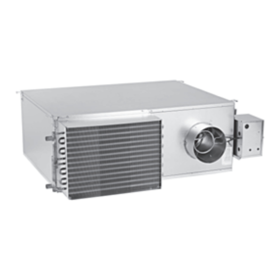
U U n n i i t t I I n n f f o o r r m m a a t t i i o o n n Figure 5. Low height series: LSEF (top) and low fan is turned on as the first stage of heat. The fan height parallel: LPCF (bottom) delivers plenum air from above the occupied space to the unit outlet, which is mixed with primary air and... - Page 19 U U n n i i t t I I n n f f o o r r m m a a t t i i o o n n Figure 8. Chilled water sensible cooling unit with hot Terminal Units. These terminal units are part of a water coil s s y y s s t t e e m m that uses a dedicated outdoor-air unit to distribute outdoor air to an air valve on each terminal...
-
Page 20: Unit Installation
Unit Installation Single-Duct VAV Units W W A A R R N N I I N N G G H H a a z z a a r r d d o o u u s s V V o o l l t t a a g g e e w w / / C C a a p p a a c c i i t t o o r r s s ! ! Figure 10. -
Page 21: Fan-Powered Vav Units And Chilled
U U n n i i t t I I n n s s t t a a l l l l a a t t i i o o n n Fan-Powered VAV Units and Table 1. Dual duct VAV unit hanger location dimensions Chilled Water Sensible Cooling Inlet... - Page 22 U U n n i i t t I I n n s s t t a a l l l l a a t t i i o o n n Figure 13. Series hanger bracket locations Flow Ring Flow Ring tubing tubing...
- Page 23 U U n n i i t t I I n n s s t t a a l l l l a a t t i i o o n n Figure 14. Low-height parallel DS02/PS02 39.1 39.1 [993] [993] Primary Airflow Primary Airflow...
- Page 24 U U n n i i t t I I n n s s t t a a l l l l a a t t i i o o n n Figure 15. Low-height series DS02/PS02/DS03 w/hot water or electric heat 32.3 [821] 32.3...
-
Page 25: Bracket Locationschilled Water Sensible Cooling Terminal
U U n n i i t t I I n n s s t t a a l l l l a a t t i i o o n n Duct Connections Bracket Locations Chilled Water Sensible Cooling Terminal All VariTrane™... -
Page 26: Discharge Duct Temperature Sensor
U U n n i i t t I I n n s s t t a a l l l l a a t t i i o o n n single row coils. For multi-row coils, always plumb damage. -
Page 27: Installation
U U n n i i t t I I n n s s t t a a l l l l a a t t i i o o n n Unit Accessibility Chilled Water Sensible Cooling Terminal Units Moisture Sensor •... -
Page 28: Stand-Alone Units
U U n n i i t t I I n n s s t t a a l l l l a a t t i i o o n n Stand-alone Units air temperature is 10°F above the zone temperature, then the control action will be heat. -
Page 29: Weights
U U n n i i t t I I n n s s t t a a l l l l a a t t i i o o n n Figure 20. Bottom access Weights Table 5. Single-duct units— lb/kg Single Wall Dual Wall Unit Size... - Page 30 U U n n i i t t I I n n s s t t a a l l l l a a t t i i o o n n Table 6. Dual-duct units — lb/kg (continued) VDDF w/Dual Wall Unit Size VDDF 80/36...
- Page 31 U U n n i i t t I I n n s s t t a a l l l l a a t t i i o o n n Table 8. Series fan–powered units — lb/kg (continued) Single Wall Dual Wall VSxF...
- Page 32 U U n n i i t t I I n n s s t t a a l l l l a a t t i i o o n n Table 10. Low–height series units — lb/kg Single Wall Dual Wall LSxF Unit Size...
-
Page 33: Unit Setup
Unit Setup Figure 21. Flow sensor ΔP vs. airflow delivery 8" x 12" 6” 8" 14" 16" 10" 12" 16" x 24" 4” 5” 0.01 1,000 10,000 Airflow (CFM) Fan Motor Amperage Reference unit submittal data and motor nameplate. Adjusting the SCR Motor Speed Control In order to make units more convenient and efficient to balance, an SCR (silicone control rectifier) is provided... -
Page 34: Electrically Commutated Motor
U U n n i i t t S S e e t t u u p p Figure 22. SCR (top) and internal potentiometer N N o o t t e e : : This feature only verifies airflow is set properly. It (bottom) does not indicate actual ECM speed. - Page 35 U U n n i i t t S S e e t t u u p p supplied to the motor. Short and long flashes are used Table 13. VPxF 04SQ ECM CFM to indicate values from 0 to 100 percent. ECM Control •...
- Page 36 U U n n i i t t S S e e t t u u p p Table 14. VPxF 05SQ ECM CFM (continued) Table 15. VPxF 06SQ ECM CFM (continued) ECM Control Board ECM Control Airflow Trane Airflow Trane Signal (b) (c)
- Page 37 U U n n i i t t S S e e t t u u p p Table 16. VSxF 03SQ ECM CFM (continued) Table 18. VSxF 05SQ ECM CFM (continued) ECM control board with 2-10 VDC, has combined fan on/off and modulation input where fan comes on when signal rises to 2 VDC and ECM Control Board Airflow...
- Page 38 U U n n i i t t S S e e t t u u p p Table 19. VSxF 06SQ ECM CFM (continued) Table 20. LSxF DS03 ECM CFM (continued) ECM Control ECM Control Board Airflow Trane Airflow Trane Board Signal (b) (c)
-
Page 39: Wiring Diagrams
Wiring Diagrams N N o o t t e e s s : : See programming guides listed below for • VV550: VAV-SVP01*-EN detailed class II low voltage unit controls wiring information on the following: • UCM 4.2: VAV-SVX01*-EN • UC400: VAV-SVX07*-EN •... -
Page 40: Box
W W i i r r i i n n g g D D i i a a g g r r a a m m s s Wiring — Electric Heater Control Box Figure 26. Single duct , single phase, 1 leg, 3 stages VAV-SVX08U-EN... - Page 41 W W i i r r i i n n g g D D i i a a g g r r a a m m s s Figure 27. Single duct, single phase, 2 legs, 3 stages VAV-SVX08U-EN...
- Page 42 W W i i r r i i n n g g D D i i a a g g r r a a m m s s Figure 28. Single duct, three phase, delta, 3 stages VAV-SVX08U-EN...
- Page 43 W W i i r r i i n n g g D D i i a a g g r r a a m m s s Figure 29. Single duct, single phase, SCR, 1 leg, 1 stage VAV-SVX08U-EN...
- Page 44 W W i i r r i i n n g g D D i i a a g g r r a a m m s s Figure 30. Single duct, single phase, SCR, 2 legs, 1 stage STAGES LINE VOLTAGE LEGEND (SEE NAMEPLATE)
- Page 45 W W i i r r i i n n g g D D i i a a g g r r a a m m s s Figure 31. Single duct, three phase, delta, SCR, 1 stage VAV-SVX08U-EN...
- Page 46 W W i i r r i i n n g g D D i i a a g g r r a a m m s s Figure 32. Single duct, single phase, 1 leg VAV-SVX08U-EN...
- Page 47 W W i i r r i i n n g g D D i i a a g g r r a a m m s s Figure 33. Fan powered, single phase, 1 leg, 2 stages VAV-SVX08U-EN...
- Page 48 W W i i r r i i n n g g D D i i a a g g r r a a m m s s Figure 34. Fan powered, single phase, 2 legs, 2 stages VAV-SVX08U-EN...
- Page 49 W W i i r r i i n n g g D D i i a a g g r r a a m m s s Figure 35. Fan powered, three phase, wye, 2 stages VAV-SVX08U-EN...
- Page 50 W W i i r r i i n n g g D D i i a a g g r r a a m m s s Figure 36. Fan powered, single phase, 1 leg, 2 stages VAV-SVX08U-EN...
- Page 51 W W i i r r i i n n g g D D i i a a g g r r a a m m s s Figure 37. Fan powered, single phase, 2 legs, 2 stages VAV-SVX08U-EN...
- Page 52 W W i i r r i i n n g g D D i i a a g g r r a a m m s s Figure 38. Fan powered, three phase, wye, 2 stages VAV-SVX08U-EN...
-
Page 53: Control Box Wiring
W W i i r r i i n n g g D D i i a a g g r r a a m m s s Control Box Wiring Figure 39. Single duct control box VAV-SVX08U-EN... - Page 54 W W i i r r i i n n g g D D i i a a g g r r a a m m s s Figure 40. Fan-powered units with PSC motors VAV-SVX08U-EN...
- Page 55 W W i i r r i i n n g g D D i i a a g g r r a a m m s s Figure 41. Fan-powered units with ECM motor VAV-SVX08U-EN...
- Page 56 W W i i r r i i n n g g D D i i a a g g r r a a m m s s Figure 42. Fan-powered units with ECV motor VAV-SVX08U-EN...
- Page 57 W W i i r r i i n n g g D D i i a a g g r r a a m m s s Figure 43. Fan-powered, old style VAV-SVX08U-EN...
- Page 58 W W i i r r i i n n g g D D i i a a g g r r a a m m s s Figure 44. Fan-powered, ECM, old style VAV-SVX08U-EN...
- Page 59 W W i i r r i i n n g g D D i i a a g g r r a a m m s s Figure 45. Fan-powered, low-height incl 10SQ, old style Fan-Powered Low-Height Control Box Fan-Powered Low-Height Control Box Duct Pressure Switch Option MOTOR 2...
- Page 60 W W i i r r i i n n g g D D i i a a g g r r a a m m s s Figure 46. Fan-powered, low-height incl 10SQ, ECM, old style Fan-Powered Low-Height Control Box Fan-Powered Low-Height Control Box w/ ECM with Electronic or DDC Controls w/ ECM...
-
Page 61: Maintenance
Maintenance Fan Motor Replacement Periodic maintenance of the VariTrane™ product is minimal, but necessary for efficient operation. Routine W W A A R R N N I I N N G G maintenance consists of inspecting/replacing the air filters of the fan-powered terminals. H H a a z z a a r r d d o o u u s s V V o o l l t t a a g g e e w w / / C C a a p p a a c c i i t t o o r r s s ! ! F F a a i i l l u u r r e e t t o o d d i i s s c c o o n n n n e e c c t t p p o o w w e e r r a a n n d d d d i i s s c c h h a a r r g g e e Motors... -
Page 62: Scr Assembly
M M a a i i n n t t e e n n a a n n c c e e SCR Assembly overheating during normal operation. The SCR assembly must always be mounted with the heat sink SCR solid state relays are used to switch a single heater fins oriented vertically (see above) with a minimum stage on and off. - Page 63 N N o o t t e e s s VAV-SVX08U-EN...
- Page 64 Trane - by Trane Technologies (NYSE: TT), a global innovator - creates comfortable, energy efficient indoor environments for commercial and residential applications. For more information, please visit trane.com or tranetechnologies.com. Trane has a policy of continuous product and product data improvements and reserves the right to change design and specifications without notice.
Need help?
Do you have a question about the VariTrane VCCF and is the answer not in the manual?
Questions and answers