Advertisement
Quick Links
™
FieldPoint
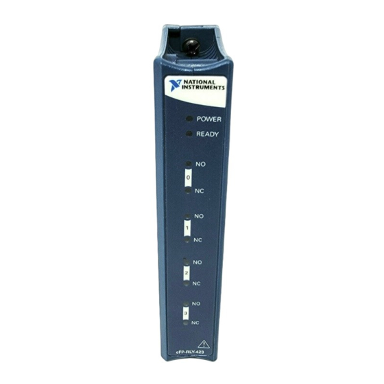
cFP-RLY-423
Four-Channel SPDT Relay Module
These operating instructions describe how to install and use the
National Instruments cFP-RLY-423. For more information about
configuring and accessing the cFP-RLY-423 over a network, refer
to the user manual for the FieldPoint network module you are
using.
Features
The cFP-RLY-423 is a Compact FieldPoint relay output module
with the following features:
•
Four single-pole double-throw (SPDT) relay channels
•
Switches up to 1.5 A at 35 VDC or 250 VAC
•
LED relay status indicators
•
Hot swappable
•
–40 to 60 °C operation
•
250 V
maximum isolation voltage
rms
•
2,300 V
rms
Installing the cFP-RLY-423
The cFP-RLY-423 mounts on a Compact FieldPoint backplane
(cFP-BP-x), which provides operating power to the module.
Installing the cFP-RLY-423 onto a powered backplane does not
disrupt the operation of the bank.
Operating Instructions
transient overvoltage protection
Advertisement

Subscribe to Our Youtube Channel
Related Manuals for NI FieldPoint cFP-RLY-423

Summary of Contents for NI FieldPoint cFP-RLY-423
- Page 1 ™ FieldPoint Operating Instructions cFP-RLY-423 Four-Channel SPDT Relay Module These operating instructions describe how to install and use the National Instruments cFP-RLY-423. For more information about configuring and accessing the cFP-RLY-423 over a network, refer to the user manual for the FieldPoint network module you are using.
- Page 2 (10 lb ⋅ in.) of torque. The nylon coating on the screws prevents them from loosening. 1 cFP I/O Module 4 Screw Holes 2 Captive Screws 5 cFP Backplane 3 cFP Controller Module Figure 1. Installing the cFP-RLY-423 cFP-RLY-423 ni.com...
- Page 3 Table 1. Terminal Assignments Terminal Numbers Channel 10,11 14,15 All of the COM terminals are connected internally and all of the terminals are connected internally. NI does not recommend using them with the cFP-RLY-423. © National Instruments Corp. cFP-RLY-423...
- Page 4 Figure 2. Install a 1.5 A, 250 V maximum, fast-acting fuse suitable for the load at the connected IC terminal to protect the module and the load from damage. Sourcing Load 1.5 A, – 250 V max Sourcing Load cFP-RLY-423 Figure 2. Basic Field Connection cFP-RLY-423 ni.com...
- Page 5 The cFP-RLY-423 has four independent Form C electromechanical relays. The relays are break-before-make. At power-up, all relays are in the NC state. Turning the relay channel on breaks the NC–IC connection and makes the NO–IC connection. Each relay can be controlled independently, or all relays can change states simultaneously.
- Page 6 For larger voltages, use diode with reverse Load breakdown 10 times circuit voltage and forward load circuit. For smaller voltages, use reverse breakdown voltage of 2 to 3 times power supply voltage. This section has been reprinted with permission from American Zettler, Inc. cFP-RLY-423 ni.com...
- Page 7 CR (RC or Snubber) Circuits Diagram Notes Circuit A is suitable for AC or DC applications, but if used with AC voltage, impedance of the load should be smaller than that of the Load CR circuit. Do not utilize for timer loads, as leakage current can cause faulty operations.
-
Page 8: Status Indicators
2,300 V . The cFP-RLY-423 provides double insulation (compliant with IEC 61010-1) for working voltages of cFP-RLY-423 ni.com... - Page 9 250 V . Safety standards (such as those published by UL and IEC) require the use of double insulation between hazardous voltages and any human-accessible parts or circuits. Never try to use any isolation product between human-accessible parts (such as DIN rails or monitoring stations) and circuits that can be at hazardous potentials under normal conditions, unless the product is specifically designed for such an application, as is the cFP-RLY-423.
-
Page 10: Specifications
35 to 55 VDC ......1 A at –40 to 55 °C 0.5 A at 55 to 60 °C 55 to 120 VDC ......0.4 A Minimum switching load....100 mA at 5 VDC DC path resistance Initial .......... ≤200 mΩ End of life........≥1.0 Ω cFP-RLY-423 ni.com... - Page 11 DC path resistance typically remains low for Note the life of the relay. At the end of relay life, the path resistance rises rapidly above 1 Ω. Load ratings apply to relays used within the specification before the end of relay life.
- Page 12 • CAN/CSA C22.2 No. 1010.1 For UL, hazardous location, and other safety certifications, refer to the product label or to ni.com Electromagnetic Compatibility CE, C-Tick, and FCC Part 15 (Class A) Compliant Emissions.......... EN 55011 Class A at 10 m FCC Part 15A above 1 GHz Immunity...........
-
Page 13: Where To Go For Support
To obtain the DoC for this product, click Declarations of Conformity Information at ni.com/hardref.nsf/ Where to Go for Support For more information about setting up the FieldPoint system, refer to these National Instruments documents: •... - Page 14 Slovenia 386 3 425 4200, South Africa 27 0 11 805 8197, Spain 34 91 640 0085, Sweden 46 0 8 587 895 00, Switzerland 41 56 200 51 51, Taiwan 886 2 2528 7227, Thailand 662 992 7519, United Kingdom 44 0 1635 523545 cFP-RLY-423 ni.com...
- Page 15 FieldPoint™, National Instruments™, NI™, and ni.com™ are trademarks of National Instruments Corporation. Product and company names mentioned herein are trademarks or trade names of their respective companies. For patents covering National Instruments products, refer to the appropriate location: Help»Patents in your software, the patents.txt file on your CD, or ni.com/patents .
Need help?
Do you have a question about the FieldPoint cFP-RLY-423 and is the answer not in the manual?
Questions and answers